NEED HELP Unknown Driver and No Start

TJBaker57

Member
Aug 16, 2015
2,900
Colorado
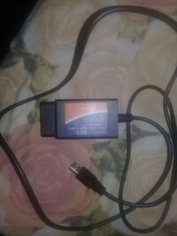
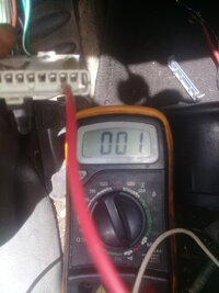
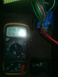
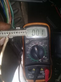
Reports of Chinese copies of the ELM327 not actually implementing the SAE J1850 VPW protocol can be readily found. Some have opened up their adapters to find pin 2 of the OBD connector not even connected. Here I use a serial terminal to test the output of an ELM327 copy for presence of a voltage output on pin 2 during a simple J1850 message. I have set the ELM to use protocol #2, SAE J1850 VPW, and I have a multimeter attached to ground and pin #2 of the OBD adapter. The meter is set to 2000 millivolts DC. The voltage can be seen to increase during the sending of the message.


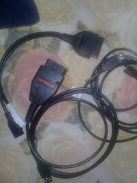
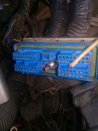
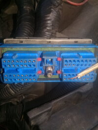
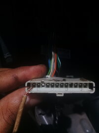
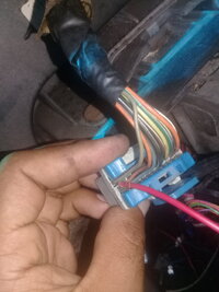
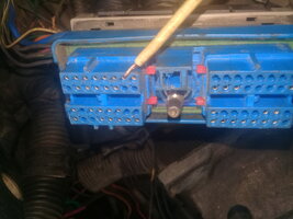
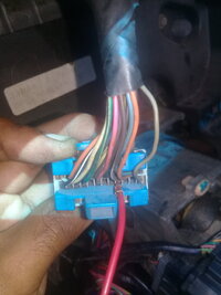
This same operation can be duplicated in the vehicle by removing the sp205 comb and connecting the voltmeter to terminal A (purple wire) and a known good ground. The purple wire from the DLC and sp205 should be tested for continuity as well as no shorts to ground or power first.

While this does not prove operability of the ELM327 copy it at least proves there is some connection internally and at the least suggests the device supports the J1850 protocol.

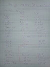
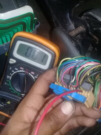
Here are 2 stills from the video with the voltmeter showing the increased voltage during message transmission.

20200920_164143_exported_618_1600646658522.jpg20200920_164143_exported_6784_1600646767749.jpg


  • Like
Reactions: Mramses

Mramses

Original poster
Member
Jul 19, 2020
322
17176352
Hello friends, today I could not do the tests due to bad weather and we were without electricity for more than 6 hours.
I am very happy to follow my case, they are all very knowledgeable and I am sure that with your help I will be able to start the truck again
 

Mramses

Original poster
Member
Jul 19, 2020
322
17176352
friends I found these two scanners. I think your hyposthesis could be happening. that the elm327 does not connect to the truck because it is a clone.
Tomorrow I'm going to try my sister's 98 cavalier.
 

Attachments

  • 16006509238431334664658.jpg
    16006509238431334664658.jpg
    323.4 KB · Views: 6
  • 16006509738841375367304.jpg
    16006509738841375367304.jpg
    274 KB · Views: 6

Mramses

Original poster
Member
Jul 19, 2020
322
17176352
friends I found these two scanners. I think your hyposthesis could be happening. that the elm327 does not connect to the truck because it is a clone.
Tomorrow I'm going to try my sister's 98 cavalier.
the other is the galleto. so that it could serve?
and also an op com
 

Attachments

  • 1600651141357162602193.jpg
    1600651141357162602193.jpg
    248.5 KB · Views: 7

Mramses

Original poster
Member
Jul 19, 2020
322
17176352
We have tried to communicate with many modules but have no success. Our elm commands are correct. It is unlikely that so many modules could all suffer bad grounds or lacking power. The Chinese copies of the ELM are known to be sometimes of inadequate construction, lacking some features. You could try to confirm that the elm are sending signals by connecting the meter to the purple wire and ground, connect no jumpers, just the elm connected to the meter. Set the meter to a low setting of say 2 volts. Use the car scanner terminal as you did yesterday. There should be a very brief change in volts when you send the "20" . There will be no change in voltage when sending any line that starts with "AT". Also no change whenever the elm replies "?"
tjbaker57 thinking a bit about what you mention I have an observation. When I connect the (+) of the tester (range 2 vdc) to the communication line of the bcm in the sp205 and to ground the end (-) I obtain, once I turn the key run, a voltage variation from 0 to 2 volts and it is fluctuating, after a few seconds it remains at 0 v. This happens the same when connecting the cable of the pcm in sp205 to (+) and (-) to ground. all this without the sp205 comb.
Unlike the gray cable cluster of the sp205 (+) and (-) ground, the voltage is fixed 1.19 vdc
Now, that fluctuating voltage is not a sign that there is a communication message from the bcm and pcm? It should be read by elm327 in the terminal option of the car scanner application
 

TJBaker57

Member
Aug 16, 2015
2,900
Colorado
tjbaker57 thinking a bit about what you mention I have an observation. When I connect the (+) of the tester (range 2 vdc) to the communication line of the bcm in the sp205 and to ground the end (-) I obtain, once I turn the key run, a voltage variation from 0 to 2 volts and it is fluctuating, after a few seconds it remains at 0 v. This happens the same when connecting the cable of the pcm in sp205 to (+) and (-) to ground. all this without the sp205 comb.
Unlike the gray cable cluster of the sp205 (+) and (-) ground, the voltage is fixed 1.19 vdc
Now, that fluctuating voltage is not a sign that there is a communication message from the bcm and pcm? It should be read by elm327 in the terminal option of the car scanner application


So you know, the PCM and BCM are connected to each other by the yellow wire that does not go through the splice comb. So testing the PCM or BCM wire at the splice comb is testing the same thing. So I would expect to see the same conditions. Yes, the voltage fluctuations are a sign of message traffic. When first powered by the key there is a lot of traffic from the BCM and these messages are sent from the BCM even if there is no module to receive them. After a few moments the traffic dies down and this is when the voltage will be seen to be lower.

There is an ELM327 command to monitor all messages on the network but it does not work well with Car Scanner. Car Scanner terminal appears to not receive the traffic but then some traffic comes in a rush so it is unreliable.
 
Last edited:

Mramses

Original poster
Member
Jul 19, 2020
322
17176352
So you know, the PCM and BCM are connected to each other by the yellow wire that does not go through the splice comb. So testing the PCM or BCM wire at the splice comb is testing the same thing. So I would expect to see the same conditions. Yes, the voltage fluctuations are a sign of message traffic. When first powered by the key there is a lot of traffic from the BCM and these messages are sent from the BCM even if there is no module to receive them. After a few moments the traffic dies down and this is when the voltage will be seen to be lower.

There is an ELM327 command to monitor all messages on the network but it does not work well with Car Scanner. Car Scanner terminal appears to not recive the traffic but then some traffic comes in a rush so it is unreliable.
after that test, disconnect the harness from the bcm and the communication line of the pcm continued the fluctuations. But when I unplugged the PCM and plugged the BCM back in, there were no voltage fluctuations on the green communication cable.
I am going to repeat all this tomorrow but could this indicate that something is wrong with the bcm?
 

TJBaker57

Member
Aug 16, 2015
2,900
Colorado
after that test, disconnect the harness from the bcm and the communication line of the pcm continued the fluctuations. But when I unplugged the PCM and plugged the BCM back in, there were no voltage fluctuations on the green communication cable.
I am going to repeat all this tomorrow but could this indicate that something is wrong with the bcm?

It could indicate a lack of communication from BCM.

I have not done that test myself. I will do that tomorrow also.
 

TJBaker57

Member
Aug 16, 2015
2,900
Colorado
At first turn of key the BCM should receive power on C3, pin A18. That would be on one of the ribbon cables. I have helped others who had troubles with the connectors of the ends of those flat ribbon cables.
 

Mramses

Original poster
Member
Jul 19, 2020
322
17176352
At first turn of key the BCM should receive power on C3, pin A18. That would be on one of the ribbon cables. I have helped others who had troubles with the connectors of the ends of those flat ribbon cables

I get it. tomorrow I check everything you are telling me.
tjbaker57, if the bcm does not send the "communication message", the modules that depend on it (bcm) do not generate responses? I mean if the bcm does not activate, the rest of the modules do not "wake up" or send a signal?
Is that why the rest of the modules do not connect? do you need the bcm message?
And the pcm even though they are sending signals, as it is not homologated to the bcm, we do not detect it for that reason? is this possible or doesn't it make a lot of sense?
the pcm that is installed is from another truck and has not been programmed
 

Mramses

Original poster
Member
Jul 19, 2020
322
17176352
I get it. tomorrow I check everything you are telling me.
tjbaker57, if the bcm does not send the "communication message", the modules that depend on it (bcm) do not generate responses? I mean if the bcm does not activate, the rest of the modules do not "wake up" or send a signal?
Is that why the rest of the modules do not connect? do you need the bcm message?
And the pcm even though they are sending signals, as it is not homologated to the bcm, we do not detect it for that reason? is this possible or doesn't it make a lot of sense?
the pcm that is installed is from another truck and has not been programmed
 
  • Like
Reactions: ek02

TJBaker57

Member
Aug 16, 2015
2,900
Colorado
Test for power at BCM C3 # A18 with key at Accessory or RUN. This pin should have power as soon as the key starts to turn. This power "awakens" the BCM, but the BCM can communicate without it. I know this because the BCM awakens when a door is opened, before the key is inserted.

IMG_20200708_190741.jpg
 

TJBaker57

Member
Aug 16, 2015
2,900
Colorado
mean if the bcm does not activate, the rest of the modules do not "wake up" or send a signal


Not true. The wake up message can be also sent by other modules. As a door is opened, that door module will send the wake up message. If the key FOB button is pressed to unlock the doors, the liftgate module receives the radio signal from the key fob and then the liftgate module sends the wakeup message. However, after the wakeup message is sent the BCM has the duty of announcing the status of the network to the whole system. And if these status messages are not sent the PCM will not crank the engine.

Here is a short example of the drivers door module sending the wakeup message. The "02" in the first line is the wakeup message. The 2nd line the drivers door module reports the door switch is open, the 3rd line the BCM reports the status of the network, the 4th line the BCM acknowledges the drivers door is open, and so on. Almost everything that happens in the vehicle is in the serial data. 50 or more messages can occur in one second or less.

08:10:18.981 88 FF A0 02 78
08:10:19.044 8A C7 A0 A1 22 78
08:10:19.064 28 FF 40 06 03 00 0F 7F
08:10:19.064 EB C6 40 61 22 62
08:10:19.167 28 FF 40 06 03 00 0F 7F
08:10:19.194 8A C7 A0 A1 22 78
08:10:19.194 28 FF 40 06 03 00 0F 7F
08:10:19.194 8A C7 A1 21 26 4A
08:10:19.194 6A EA 40 20 91 00 43
08:10:19.194 8A C7 A2 21 40 1C
08:10:19.194 6A EA 40 20 9E 00 E0
08:10:19.211 8A C7 A2 21 41 01
 
Last edited:
  • Like
Reactions: Mramses

budwich

Member
Jun 16, 2013
2,050
kanata
this is the GM SI for troubleshooting the DLC when the system can't connect. hopefully it will help. As explorer pointed out, the OP needs to ensure that his tools are working properly (ie. elm, software, AND meter) otherwise, a basis for analysis will be unreliable and lead in wrong directions. The basic electrical integrity of the modules involved has to ascertained. Without that, it is unlikely that progress will be made.
 

Attachments

  • dlc2002 tbl.pdf
    32.4 KB · Views: 6

TJBaker57

Member
Aug 16, 2015
2,900
Colorado
Here is a short example of the drivers door module sending the wakeup message. The "02" in the first line is the wakeup message.


So just for the curious folks, here is a page from the SAE document 2178-4 that is the specification standard for the J1850 VPW protocol that our pre-2008 trucks use for communications. It is here in 8.46 that I find the definition of the bus wake up secondary ID of "02" under the "Status ID" of Functional address $FF. With this document and a lot of studying I have learned to read much of what is communicated on the class 2 serial bus and have dozens of hours of recorded traffic to play with.

Screenshot_20200921-072837~01.png
 
  • Like
Reactions: Expeditor

Expeditor

Member
Nov 19, 2018
35
Nashville
If OP does not have a scope or working scan tool he can try what this guy suggest. Video is old but from very reliable source, Delphi trainer. Very long video, so start at 53:20 for diagnosing a no start, no communication with simple tools. The video also shows how to trouble shoot the different modules contributing to the no start. There are many other video that show the same thing done in different ways but have the same results, this is just plain and simple.


TJBaker57

Member
Aug 16, 2015
2,900
Colorado
GM SI appears to declare the unless the BCM issues a wake up message that other modules in the vehicle may not communicate. This video demonstrates that other modules do indeed communicate without a BCM present on the network. For sure, the engine cannot be started or otherwise operated but you can troubleshoot other modules on the network even without a functional BCM. First seen is a Tech 2 displaying engine data, Transmission data, ATC data, and EBCM data. Next the Torque app connects and displays various engine data. Finally, in Torque I command the fuel pump and then the front axle disconnect to breifly operate which you will hear. All of this happens through J1850 communication with various modules where no BCM is present on the vehicle network.


Mramses

Original poster
Member
Jul 19, 2020
322
17176352
GM SI appears to declare the unless the BCM issues a wake up message that other modules in the vehicle may not communicate. This video demonstrates that other modules do indeed communicate without a BCM present on the network. For sure, the engine cannot be started or otherwise operated but you can troubleshoot other modules on the network even without a functional BCM. First seen is a Tech 2 displaying engine data, Transmission data, ATC data, and EBCM data. Next the Torque app connects and displays various engine data. Finally, in Torque I command the fuel pump and then the front axle disconnect to breifly operate which you will hear. All of this happens through J1850 communication with various modules where no BCM is present on the vehicle network.

Good afternoon here the resistance and voltage values measured independently in the sp205 and sp306. without being connected the pcm.
 

Attachments

  • 20200925_150756.jpg
    20200925_150756.jpg
    211.6 KB · Views: 17
  • 20200925_150010.jpg
    20200925_150010.jpg
    200.9 KB · Views: 13

budwich

Member
Jun 16, 2013
2,050
kanata
not sure what to say... you are doing good but its tough with "internet" and language.
Note: as one may expect, that most interfaces to the bus should read similar with resistance as they likely have the same basic electrical components in their design. Having said that, it would appear that some have very low resistance readings which would appear that those interfaces may have an issue AND if they are left connected to the data bus, may cause problems. That said, as suggested along the way, basically, you need a PCM and BCM plus maybe an instrument cluster (to get visual indications along the way). So the focus should be on the PCM and BCM.

You have readings of the resistance from the splice pack connector to the PCM and PCM. One at a time jumper only those units at the splice pack to the DLC connector pin at the splice pack. Then measure the resistance on the data pin at the DLC connector at the dash (using the ground pin at the dash connector as a ground reference. It should read the same as those previous readings. You need to confirm this for each unit (pcm and BCM) independently AND then again with them both connected / jumpered. Go from the those results.

ADDED NOTE: note that some resistance readings may be "OFF" because it is likely you have the battery connected and it is possible that some of those interfaces are more active than others which may result in different readings.

ADDED NOTE: splice pack is SP206, not 306
 
Last edited:

budwich

Member
Jun 16, 2013
2,050
kanata
once you have done the previous check, as mentioned there is a direct PCM to BCM link... on pin 58 of connector 1 at the pcm and pin f14 of connector c2 at the BCM. Both of those should have similar resistance readings as the other interfaces at those units.

After that you need to check voltages at the BCM, there are a few to confirm that electrically, the bcm is happy.
 

Mramses

Original poster
Member
Jul 19, 2020
322
17176352
once you have done the previous check, as mentioned there is a direct PCM to BCM link... on pin 58 of connector 1 at the pcm and pin f14 of connector c2 at the BCM. Both of those should have similar resistance readings as the other interfaces at those units.

After that you need to check voltages at the BCM, there are a few to confirm that electrically, the bcm is happy.
yes. yellow wire confirmed c1 58 cfm to f14 bcm.
yes. confirm the bcm input voltages and grounds according to the bcm diagram
 

Attachments

  • Screenshot_20200925-195656.png
    Screenshot_20200925-195656.png
    110.2 KB · Views: 7
  • Screenshot_20200925-195652.png
    Screenshot_20200925-195652.png
    126.7 KB · Views: 7

budwich

Member
Jun 16, 2013
2,050
kanata
yes. yellow wire confirmed c1 58 cfm to f14 bcm.
yes. confirm the bcm input voltages and grounds according to the bcm diagram
you can't just post a picture of the schematic... you need to post the exact ones that you tested and the value of those... otherwise we are guessing at what you are saying with "confirm input voltages". This is hard enough... don't do short cut posts otherwise effort will be lost.
 
Last edited:

TJBaker57

Member
Aug 16, 2015
2,900
Colorado
I think post 246 shows this circuit resistance /continuity measurement?

Or is it each modules resistance to ground that is what is requested?
 

budwich

Member
Jun 16, 2013
2,050
kanata
He should be trying to test "well defined" portions of the circuit. All measurements need to be done to a well known ground. Further, as you pointed out in the general area of posts (ie. 246, 247, 248, etc), there are some measurements posted but with some "differences" with meter "operation". This is to get some consistency with measurements (which appear to be now with his 20k ohm scale) to be compared against the measurements that he finally produced likes yours at the splice pack points which can provide some "reference" for further testing, which I have asked for to slowly move to the dlc connector which should provide a "complete" electrical path check to those data bus points of interested at the PCM and BCM... again looking for consistency in measurement technique and results. This is just a first small step. Then as has been done but needs to be rechecked, at the incoming wiring to the PCM (and BCM), post voltage results of the exact wires tested and results of those wires as again there was "discussion" for instance, around pin 17/ wiring location which I believe was not fully confirmed... with confusion of location and result which I think was posted as "0" (but may have been corrected)... this just to confirm / check.

The same test of voltage that was done on the PCM needs to be posted for the BCM as there are similar ones plus potentially extra ones dealing with battery positive voltage, etc. as the GM SI indicates that those should also exist or may indicate a problem internally with the BCM (and PCM) of not supplying / switching those (NOTE: these might be harder to check individually because cabling has to be in place... but the alternative might be to do simple resistance checks on those and compare the results against the various pins for consistency). Lastly, again, from the GM SI, those voltages / pins especially in association with the powering of the unit in question (ie. PCM, BCM), a check of the internal resistance at those points needs to be confirmed again, looking for "unusual" high or very low readings again looking for consistency across pins and or devices. For instance, the voltage being delivered to the PCM might be fine but the subtending internal PCM circuit has been "blown" and has high / open resistance. Again you will ask what should it be... I don't know... and really don't care much about the absolute value but it can be compared against devices and "similar circuits" in devices as a "thumb rule" check / comparison.... as long as there is some degree of certainty about the measurement technique and meter.

Lastly, the OP was going to check the operation of the OBD interface device that he is using against another vehicle to ensure it can work properly. I am not sure this was reported.
 
Last edited:

TJBaker57

Member
Aug 16, 2015
2,900
Colorado
I certainly get where you are coming from. So much information in doubt and scattered about. Makes it very difficult to do a logical diagnosis.

I should add that some of my measurements need confirmation and correction before taken as a reference point.

I have even entertained the notion of maybe grabbing another PCM & matching BCM from the nearest boneyard just for testing pruposes.
 

budwich

Member
Jun 16, 2013
2,050
kanata
You have gone "way far" in actual information / comparison with a "working system"... I can't say enough greatness about that basis. It has certainly been a long thread. I guess I go back to the original problem.... motor work done, the result "no start" which I think the OP indicate that there was no starter action (although language is in the way) but if he jumped the start relay, he got starter action but still no start (ie. crank, no start). Then there was problems with the IP display and after much back and forth, with another PCM got a check engine light to show but still no crank, no start. This led to attack of the data link and bus which is fine but as you pointed out, one only needs the BCM and PCM for a start condition / engine run. So the focus should remain on checking the BCM and PCM for proper conditions especially IF ultimately somehow, it can be made to communicate with an obd interface somehow. To me, it is unlikely to be a failed BCM as it is unlikely that motor work would touch the BCM. It is likely the PCM was touched along with cabling to and from. Plus, there was some playing with the ignition switch which can leave a question mark in its integrity.

I guess to me it is only possible to work thru the basic level electrical until it can be ascertained that indeed the "physical layer" is OK. There are many points that the forum has tried to do this both with the IP display and via the comms of the data bus / DLC / OBD interface.... ALL appear to have shortcomings in their "integrity" on this particular vehicle.... so it continues to be a few steps forward and then backward again. :-(

Ultimately wondering if the problem is relatively simple... if he jumps the relay AND provides fuel in the intake (spray starter fluid), does the system attempt / sputter to start?
 
Last edited:

Mramses

Original poster
Member
Jul 19, 2020
322
17176352
T
He should be trying to test "well defined" portions of the circuit. All measurements need to be done to a well known ground. Further, as you pointed out in the general area of posts (ie. 246, 247, 248, etc), there are some measurements posted but with some "differences" with meter "operation". This is to get some consistency with measurements (which appear to be now with his 20k ohm scale) to be compared against the measurements that he finally produced likes yours at the splice pack points which can provide some "reference" for further testing, which I have asked for to slowly move to the dlc connector which should provide a "complete" electrical path check to those data bus points of interested at the PCM and BCM... again looking for consistency in measurement technique and results. This is just a first small step. Then as has been done but needs to be rechecked, at the incoming wiring to the PCM (and BCM), post voltage results of the exact wires tested and results of those wires as again there was "discussion" for instance, around pin 17/ wiring location which I believe was not fully confirmed... with confusion of location and result which I think was posted as "0" (but may have been corrected)... this just to confirm / check.

The same test of voltage that was done on the PCM needs to be posted for the BCM as there are similar ones plus potentially extra ones dealing with battery positive voltage, etc. as the GM SI indicates that those should also exist or may indicate a problem internally with the BCM (and PCM) of not supplying / switching those (NOTE: these might be harder to check individually because cabling has to be in place... but the alternative might be to do simple resistance checks on those and compare the results against the various pins for consistency). Lastly, again, from the GM SI, those voltages / pins especially in association with the powering of the unit in question (ie. PCM, BCM), a check of the internal resistance at those points needs to be confirmed again, looking for "unusual" high or very low readings again looking for consistency across pins and or devices. For instance, the voltage being delivered to the PCM might be fine but the subtending internal PCM circuit has been "blown" and has high / open resistance. Again you will ask what should it be... I don't know... and really don't care much about the absolute value but it can be compared against devices and "similar circuits" in devices as a "thumb rule" check / comparison.... as long as there is some degree of certainty about the measurement technique and meter.

Lastly, the OP was going to check the operation of the OBD interface device that he is using against another vehicle to ensure it can work properly. I am not sure this was reported.
I certainly get where you are coming from. So much information in doubt and scattered about. Makes it very difficult to do a logical diagnosis.

I should add that some of my measurements need confirmation and correction before taken as a reference point.

I have even entertained the notion of maybe grabbing another PCM & matching BCM from the nearest boneyard just for testing pruposes.
That would be a very good friend because if they become equal to their values of pcm, bcm and other modules we could discard mine as well as the resistance values of the pcm circuits
 

TJBaker57

Member
Aug 16, 2015
2,900
Colorado
You have gone "way far" in actual information / comparison with a "working system"... I can't say enough greatness about that basis. It has certainly been a long thread. I guess I go back to the original problem.... motor work done, the result "no start" which I think the OP indicate that there was no starter action (although language is in the way) but if he jumped the start relay, he got starter action but still no start (ie. crank, no start). Then there was problems with the IP display and after much back and forth, with another PCM got a check engine light to show but still no crank, no start. This led to attack of the data link and bus which is fine but as you pointed out, one only needs the BCM and PCM for a start condition / engine run. So the focus should remain on checking the BCM and PCM for proper conditions especially IF ultimately somehow, it can be made to communicate with an obd interface somehow. To me, it is unlikely to be a failed BCM as it is unlikely that motor work would touch the BCM. It is likely the PCM was touched along with cabling to and from. Plus, there was some playing with the ignition switch which can leave a question mark in its integrity.

I guess to me it is only possible to work thru the basic level electrical until it can be ascertained that indeed the "physical layer" is OK. There are many points that the forum has tried to do this both with the IP display and via the comms of the data bus / DLC / OBD interface.... ALL appear to have shortcomings in their "integrity" on this particular vehicle.... so it continues to be a few steps forward and then backward again. :-(

Ultimately wondering if the problem is relatively simple... if he jumps the relay AND provides fuel in the intake (spray starter fluid), does the system attempt / sputter to start?


You have a solid grasp of the issues at play here. Let me add a notion to this that may explain why I have been hammering away at trying to get some confirmation of communications on the serial data bus.

The PCM was replaced but it was reported that there has never been seen a "security" light that one would expect to see with a PCM change.

I have seen no evidence of communications apparent in the cluster.

No indicators from the PCM that would confirm data transfer such as PRND321 range position, oil pressure (faked by disconnecting the switch), and so on.

If the cluster isn't communicating then the Security light will not be on. I have been researching the serial data and can say the security light is indeed activated by serial data from the BCM to the IPC with the message "6A EA 40 A0 9E 00".

So if the cluster isn't communicating, whatever the reason, then it may very likely be that a "Security Relearn" is still required due to the PCM replacement and the no crank condition is the result.

Shoot me down? ?
 
  • Like
Reactions: Mramses

TJBaker57

Member
Aug 16, 2015
2,900
Colorado
Here is a little test / demonstration I did this morning to show what items of the cluster depend on serial data transmission on the class 2 bus..

The lights remaining on at the end of the video are a result of my sending messages as the test tool. Some indicators reactivate if not turned off by the actual module responsible for that system. If I spoof the "OFF"message as being from say the EBCM or the PCM then the indicator lights will remain off and not reactivate.

 
  • Like
Reactions: Mramses

budwich

Member
Jun 16, 2013
2,050
kanata
you continue to amaze with your effort and info. Personally, I only know enough to be dangerous.
I am not suggesting there isn't a security type issue... but I don't believe that can come from engine work. If anything, wiring and ignition switch "playing". The "wiring" would issues providing proper electrical to the BCM and ignition switch. The "playing" would be disturbing the ignition switch such that it no longer recognizes the key actions properly via the "theft wire induction / resistance" to the bcm.

Ultimately, IF one believes the OP's instrument cluster display, the fact that there is a "battery light" is likely a meaningful indication that some form of basic electrical is not happy. From my limited experience (leaving a truck for months without starting / charging... :-( ), the battery light on is a bad thing on these vehicles.
 
  • Like
Reactions: Mramses

TJBaker57

Member
Aug 16, 2015
2,900
Colorado
you continue to amaze with your effort and info.

Often more so the effort than the info!! :wink:

am not suggesting there isn't a security type issue... but I don't believe that can come from engine work

The replacement of the PCM brings the security issue. A replacement PCM does not know the correct password for the BCM and thus will not be granted permission to crank by the BCM. A Security Relearn allows the replacement PCM to learn the correct password.

disturbing the ignition switch such that it no longer recognizes the key actions properly via the "theft wire induction / resistance" to the bcm.

This I imagine is possible. I say imagine because I have no real knowledge in this area except the general notion that there's a resistance in there that drops a 12 volt signal and needs to match a programmed value in the BCM. The resistance varies between vehicles. Or so I have read somewhere.

the fact that there is a "battery light" is likely a meaningful indication that some form of basic electrical is not happy.

The battery charge indicator is one of those indicators enabled and disabled by serial data as far as my tests have shown. The PCM is responsible for that serial data message which reads "8A EA 10 A0 8E 00" for enable. A failure of cluster communications and that light doesn't turn off.

I just completed a comparison of my cluster with and without the cluster serial data line connected with key in RUN position. All other vehicle modules jumpered, only the cluster out of the loop. Without the serial data line connected the battery charge indicator remined on. With the cluster connected to the serial line the battery charge indicator turns off. Other lights that remained on when serial data was disconnected from only the cluster were the check gages, ABS, Airbag and passenger airbag, low fuel indicator, PRND321 range indicator.

Gauges inoperative without serial data to cluster were volts, fuel level, oil pressure, engine coolant.
 
  • Like
Reactions: Mramses

budwich

Member
Jun 16, 2013
2,050
kanata
OK... so if I understand this, you need a security re-learn BUT I assume you would need to able to talk to the BCM (and PCM) as a normal "test" to be successful at performing a re-learn sequence in some form... which gets back to confirm basic electrical or replacing units with known working units (and vehicle programming).
 
Last edited:
  • Like
Reactions: Mramses

Mramses

Original poster
Member
Jul 19, 2020
322
17176352
C1 resistance 59 pcm to sp205 dark green wire
 

Attachments

  • 20200927_103446.jpg
    20200927_103446.jpg
    423.9 KB · Views: 3
  • 20200927_103426.jpg
    20200927_103426.jpg
    400.1 KB · Views: 3

Mramses

Original poster
Member
Jul 19, 2020
322
17176352
resistance C1 58 pcm to C2 F14 bcm yellow wire
 

Attachments

  • 16012175143311491476203.jpg
    16012175143311491476203.jpg
    449.1 KB · Views: 1
  • 1601217681556498768372.jpg
    1601217681556498768372.jpg
    443.7 KB · Views: 1

Mramses

Original poster
Member
Jul 19, 2020
322
17176352
resistance C1 B1 bcm to sp205 light green wire7
 

Attachments

  • 16012182090321410215881.jpg
    16012182090321410215881.jpg
    204.4 KB · Views: 2
  • 16012182417582085194639.jpg
    16012182417582085194639.jpg
    247.4 KB · Views: 2

Mramses

Original poster
Member
Jul 19, 2020
322
17176352
sp205 wire gray resistance to Cluster B1
 

Attachments

  • 1601218548323-2070316957.jpg
    1601218548323-2070316957.jpg
    338.4 KB · Views: 2
  • 1601218588923-391998184.jpg
    1601218588923-391998184.jpg
    399.3 KB · Views: 2

Mramses

Original poster
Member
Jul 19, 2020
322
17176352
resistance C1 7 pcm to cluster B4
 

Attachments

  • 1601218870935-1628897329.jpg
    1601218870935-1628897329.jpg
    1 MB · Views: 2
  • 1601219040138-520188307.jpg
    1601219040138-520188307.jpg
    384.6 KB · Views: 4

Forum Statistics

Threads
23,332
Posts
638,005
Members
18,537
Latest member
moscoreli

Members Online