The command is incorrect. Not "AT 10"
Send this.....
AT SH 6C FE F1
20
I forgot one line.
Also send this before the others.
AT H1
This command "AT H1" turns on the headers
The command is incorrect. Not "AT 10"
Send this.....
AT SH 6C FE F1
20
friend, what else should I check?I forgot one line.
Also send this before the others.
AT H1
This command "AT H1" turns on the headers
If the PCM I'm testing was not the one in the truck, should it still turn on? without programming?
I do not understand why the anti-theft light does not appear if it is the PCM of another friend truck?
ok I already sent you the results friendIf there is a communications problem in the instrument panel the security light as well as many other functions of the instrument cluster will not light or work.
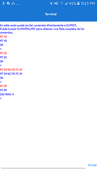
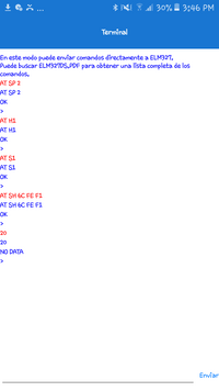
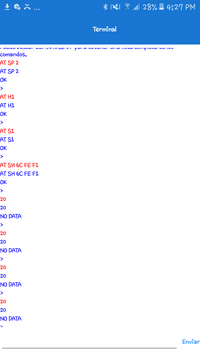
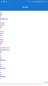
Show us the results of sending to the elm327....
AT H1
AT S1
AT SH 6C FE F1
20
ok I already sent you the results friend
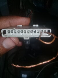
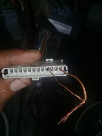
jumper input A, B and G of sp205
The results you sent most recently have the wrong commands. I do not see results of these commands following here....
AT H1
AT S1
AT SH 6C FE F1
20
These are the results I need. Not "AT 10"
jumper input A, B and G of sp205
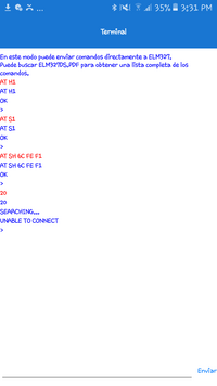
You are so close!! Almost right. The "20" needs to be on a separate line by itself, after the AT SH 6C FE F1.
Disconnect the cluster wire from G.
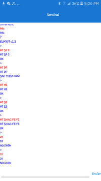
The ISO 9141-2 is not the right protocol so we must again set the right protocol. Add the AT SP 2 before the AT SH 6C FE F1.
So send it EXACTLY like what you see here. Each line as it shows here.
AT SP 2
AT H1
AT S1
AT SH 6C FE F1
20
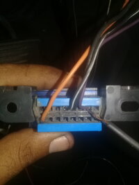
without jumper cluster. only purple and pcm
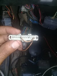
should i connect the comb sp 306? because I have it disconnected.I know this is frustrating. Try sending the " 20" a second and maybe third time. Sometimes the network doesn't wake up the first time. Also, try with the jumper from purple to blue/white and no jumper to PCM or BCM, only purple to blue/white. Send same commands as you last sent.
should i connect the comb sp 306? because I have it disconnected.
help me friend I do not understand why we do not find changes or signs of life
Yes. Install the comb in the rear. And the key must be at RUN
The commands you sending are correct. Most of the modules on the rear splice pack are door and endgate modules. You previously stated the doors do not work. I would keep trying other modules looking for an answer from one of them. Try the TCCM next on terminal C, dark green/white wire.

Truly, I do not understand. There should be a response. I have been reviewing your tests and pictures. Are we certain the purple wire has continuity? The elm needs only power and the purple wire to pin #2 of the 16 pin OBD connector. We know elm has power. If there was a break in the purple wire we would get these same results, but I believe you have checked this purple wire thoroughly.
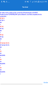
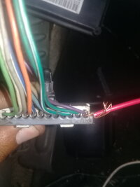
This from my vehicle purple wire jumpered to dark green/white TCCM.
Edited: The last blue line in the image is an answer from the TCCM.
View attachment 97150
only Blue
both elm327
only Blue
I have seen where you typed in " ATZ" and one answered 1.5 and another answered 2.1.
There have been reports I have read from some users that newer ELM copies no longer support our old trucks that use SAE J1850 VPW. These users have been unable to connect to our old trucks. I would check again with ATZ. I suspect the 1.5 version to be a better choice.
Edit: try both
I think it is not the same year. but trust me for having only the same connectors. that is not the same year influences?can you tell us again, what year truck the second PCM comes from?
Hello friend, what tests are we going to perform? If a module has power, ground and data line, can it communicate with it?I am puzzled. Only other test I can come up with is to try the PCM alone. To do this would require jumper from purple to PCM dark green and disconnect the connectors at the BCM to isolate the yellow wire between PCM and BCM.
What is the history of the truck. Did it run OK before the engine work? Did something else happen to it that might have caused electrical damages?
I can think of no reason that none of the modules respond to the elm devices.
Hello friend, what tests are we going to perform? If a module has power, ground and data line, can it communicate with it?
should elm read it?
For example, if the pcm is given the 4 power and ground, should it have communication? without being connected to the branch of the truck
Perhaps the issues involved here concerns the "Ground" Side of these Front Cabin Data Bus and IPC Class 2 Connections.
Hello friend, what tests are we going to perform? If a module has power, ground and data line, can it communicate with it?
should elm read it?
For example, if the pcm is given the 4 power and ground, should it have communication? without being connected to the branch of the truck