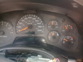
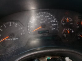
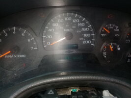
NEED HELP Unknown Driver and No Start

budwich

Member
Jun 16, 2013
2,203
kanata
that is somewhat of a good question. I have never monitored the data on the bus on my 2008.
Have you checked the other data output of the bcm which goes directly to the PCM... C2-f14 on the bcm, c1-58 on the pcm.

NOTE: somewhat related to this is the way that you are testing for grounds. The test IS NOT done by taking a voltage measurement. It is done by doing a resistance measurement to a KNOWN ground. As a result, it is possible that you have not verified the grounds on the devices.
 

budwich

Member
Jun 16, 2013
2,203
kanata
friends, is it possible to use BCM, PCM and IP or cluster of another truck and require reprogramming? what happens in this case? please
My pre-account is going to be able to do tests avoiding a reprogramming of the BCM or IP or PCM
I may have misunderstood what you are trying to say with this. I do believe that you can take a working bcm, pcm and ip from another truck and connect them to your truck using the jumpers at the splice block and then you should be able to talk them thru the DLC IF your elm327/app is working properly. You will not be able to operate your truck but you should be able to communicate with the modules especially the PCM.
 

Mramses

Original poster
Member
Jul 19, 2020
322
17176352
that is somewhat of a good question. I have never monitored the data on the bus on my 2008.
Have you checked the other data output of the bcm which goes directly to the PCM... C2-f14 on the bcm, c1-58 on the pcm.

NOTE: somewhat related to this is the way that you are testing for grounds. The test IS NOT done by taking a voltage measurement. It is done by doing a resistance measurement to a KNOWN ground. As a result, it is possible that you have not verified the grounds on the devices.
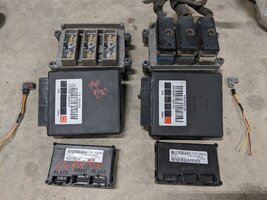
yes. check the resistance between yellow wire connecting pcm and bcm. also the lines from bcm to sp205 and pcm to sp205.
the resistors give 1 ohm in all cases.
 

Mramses

Original poster
Member
Jul 19, 2020
322
17176352
I may have misunderstood what you are trying to say with this. I do believe that you can take a working bcm, pcm and ip from another truck and connect them to your truck using the jumpers at the splice block and then you should be able to talk them thru the DLC IF your elm327/app is working properly. You will not be able to operate your truck but you should be able to communicate with the modules especially the PCM.
yes. something like that.
I wanted to know if it is possible to use the computers in another truck and turn on mine.
the question is: to do this what is needed? sensor key, bcm, pcm something else? or nothing can be done without reprogramming.
excuse my insistence but I turn to your knowledge and experience to know is it possible or not
 

budwich

Member
Jun 16, 2013
2,203
kanata
yes. check the resistance between yellow wire connecting pcm and bcm. also the lines from bcm to sp205 and pcm to sp205.
the resistors give 1 ohm in all cases.
the pins / wires that I indicated to you do not go to the splice pack, they are direct connection between the bcm and pcm. AS you did with the other data wires, look at the voltage on that wire link.
 
Last edited:

TJBaker57

Lifetime VIP Donor
Member
Aug 16, 2015
3,325
Colorado
the pins / wires that I indicated to you do not go to the splice pack, they are direct connection between the bcm and pcm. AS you did with the other data wires, look at the voltage on that wire link.


I was suspicious about that very wire. I wondered if it was the very same communications as serial data bus we all generally concern ourselves with. Why did GM run this secondary wire I wondered. So I have multiple ELM adapters and also have OBD2 harness pigtails so I set up to monitor and record both the primary OBD2 DLC with one ELM and a second ELM adapter on the yellow direct line from PCM to BCM. I simultaneously recorded traffic and then compared the two in a spreadsheet and found the serial data to be identical at least as for the few minutes of data I recorded.

So why did they choose to run this redundant line? Hard to say with anything but speculation. Seems like GM wanted to maintain that PCM to BCM communications even with the splice pack comb removed. Maybe the splice pack connection is used in assembly line diagnostics? But then they could have maintained the PCM/BCM connection in their assembly line diagnostics equipment. It's all guesswork.

It's worth mentioning that I have not ever yet checked continuity between the yellow and light green BCM serial data terminal pins. So there still exists the possibility that there could be 'private' communications on this line between those 2 modules and I just didn't capture any during my brief recording. My recording DID include the startup sequence where the security checks are done and these are identical, byte for byte on both lines.
 
  • Like
Reactions: budwich

Mramses

Original poster
Member
Jul 19, 2020
322
17176352
the pins / wires that I indicated to you do not go to the splice pack, they are direct connection between the bcm and pcm. AS you did with the other data wires, look at the voltage on that wire link.

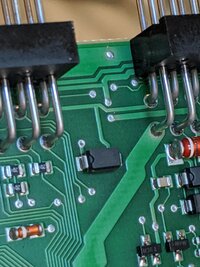
Here I meant: measure resistance disconnected the harness, from the PCM in C1 58 and C1 F14 of the BCM. the resistance measured was 1 ohm, the same as from PCM C1 59 to SP205 and C1 B1 to SP205 for BCM. I uploaded the images of the measurements at the points and the results of the tester reading
 

budwich

Member
Jun 16, 2013
2,203
kanata
Here I meant: measure resistance disconnected the harness, from the PCM in C1 58 and C1 F14 of the BCM. the resistance measured was 1 ohm, the same as from PCM C1 59 to SP205 and C1 B1 to SP205 for BCM. I uploaded the images of the measurements at the points and the results of the tester reading
NO!.... I want you to measure the voltage on that wirelink just like you did for the wire going to the splice pack from the BCM which you said had NO voltages as compared to the other devices that you measured which had some minor changes of voltages to perhaps indicate some data activity.
TJbaker has just confirmed that data is being sent out both data link pins on the BCM on his truck.
 

TJBaker57

Lifetime VIP Donor
Member
Aug 16, 2015
3,325
Colorado
In a day or two I should have more data to consider. Picked up some modules at a couple U-Pull-and-Pay. 2 sets of PCM, BCM, and TCCM (because they are easy to get out and I want to do some memory scans on them). One set from a 2003 and one set from a 2002. Would have liked to grab a cluster but didn't have the time. Also took the passkey sensors for those BCM to measure their resistances and also should allow me to simulate normal key ON condition for these BCM, having their matching passkey sensors.

IMG_20200930_201418.jpg
 
  • Like
Reactions: Mramses

Mramses

Original poster
Member
Jul 19, 2020
322
17176352
In a day or two I should have more data to consider. Picked up some modules at a couple U-Pull-and-Pay. 2 sets of PCM, BCM, and TCCM (because they are easy to get out and I want to do some memory scans on them). One set from a 2003 and one set from a 2002. Would have liked to grab a cluster but didn't have the time. Also took the passkey sensors for those BCM to measure their resistances and also should allow me to simulate normal key ON condition for these BCM, having their matching passkey sensors.

View attachment 97542
Hello Friend how are you?
how was the trip?
What are the key sensors to "On" the BCM?
I was able to get another BCM with its PCM and IP or cluster from another truck from the same year but I have not done any measurements or tests yet.
What would I need to be able to use it in my truck?
today I am going to carry out the resistance measurements of the PCM, BCM and cluster pins to see if they register the same values. I do not want to test it in the truck without first not being sure that it will cause a failure of these equipment
 

Mramses

Original poster
Member
Jul 19, 2020
322
17176352
In a day or two I should have more data to consider. Picked up some modules at a couple U-Pull-and-Pay. 2 sets of PCM, BCM, and TCCM (because they are easy to get out and I want to do some memory scans on them). One set from a 2003 and one set from a 2002. Would have liked to grab a cluster but didn't have the time. Also took the passkey sensors for those BCM to measure their resistances and also should allow me to simulate normal key ON condition for these BCM, having their matching passkey sensors.

View attachment 97542
How can I get that step sensor that is located in the steering column? where is the key. help me to disassemble it please
 

TJBaker57

Lifetime VIP Donor
Member
Aug 16, 2015
3,325
Colorado
How can I get that step sensor that is located in the steering column? where is the key. help me to disassemble it please

The passlock sensor is not meant to be removed from the lock mechanism. Since I was not concerned with the condition of these junk cars I broke them free. One came out fairly intact and the other broke into several pieces.
 

Mramses

Original poster
Member
Jul 19, 2020
322
17176352
The passlock sensor is not meant to be removed from the lock mechanism. Since I was not concerned with the condition of these junk cars I broke them free. One came out fairly intact and the other broke into several pieces.
so should i disassemble it as a single set?
 

Mramses

Original poster
Member
Jul 19, 2020
322
17176352
The passlock sensor is not meant to be removed from the lock mechanism. Since I was not concerned with the condition of these junk cars I broke them free. One came out fairly intact and the other broke into several pieces.
can I use the same pitch sensor for another BCM?
 

TJBaker57

Lifetime VIP Donor
Member
Aug 16, 2015
3,325
Colorado
worth mentioning that I have not ever yet checked continuity between the yellow and light green BCM serial data terminal pins. So there still exists the possibility that there could be 'private' communications on this line

Here is conclusive proof that indeed the two serial data wires from the BCM are in fact identical. Pin B1 and pin F14 are directly connected internally seen here...

IMG_20201001_115601.jpg
 
  • Like
Reactions: Mramses

budwich

Member
Jun 16, 2013
2,203
kanata
how easy is it to disassemble either the BCM or PCM to look for obvious physical electrical damage?
 

Mramses

Original poster
Member
Jul 19, 2020
322
17176352
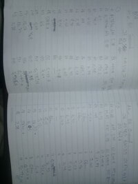
I did not find very different values between one bcm and the other that I have. except A11-A17
A11-B14
A11-A15
A11-B19
 

Attachments

  • 16015773443041303427029.jpg
    16015773443041303427029.jpg
    289.1 KB · Views: 7

Mramses

Original poster
Member
Jul 19, 2020
322
17176352
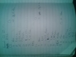
3 PCM readings
there is no variation except for the bad
 

Attachments

  • 1601577932641-2013431600.jpg
    1601577932641-2013431600.jpg
    811 KB · Views: 5

Mramses

Original poster
Member
Jul 19, 2020
322
17176352
friends with the other bcm the truck began to turn on the courtesy lights and the LEDs of the light selectors. now when turning the key with only the BCM connected, the voltage fluctuates between 0.3 to 3 v. This bcm is good but the anti-theft indicator or the high light does not come on
 

Mramses

Original poster
Member
Jul 19, 2020
322
17176352
with the change of the cluster there is already a fluctuating voltage from 0.3 to 3 vdc. It is no longer fixed at 1.19 vdc.
I have done all the tests with the sp205 and sp 206 disconnected. the truck won't start or do anything but a lot of courtesy lights went on
 

Mramses

Original poster
Member
Jul 19, 2020
322
17176352
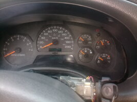
friends connect the BCM light green cable with gray cluster on the sp205 and all friends gauges will be activated.
I still do not connect the pcm. But there is fluctuating voltage on the communication line jumper between light green and gray
 

Attachments

  • 1601582550799-1007424602.jpg
    1601582550799-1007424602.jpg
    342.1 KB · Views: 6

Mramses

Original poster
Member
Jul 19, 2020
322
17176352
I activate the whole cluster and until the prnd indicator. I have jumper between light green, gray and dark green cable. BCM, cluster and PCM
but it does not start. I have driver 1 in the cluster
 

Attachments

  • 1601583471473-2056013052.jpg
    1601583471473-2056013052.jpg
    397.5 KB · Views: 8

Mramses

Original poster
Member
Jul 19, 2020
322
17176352
Friend I see driver 1. but I turn on ignition and it does nothing, everything turns off until the switch returns
 

TJBaker57

Lifetime VIP Donor
Member
Aug 16, 2015
3,325
Colorado
These are some good signs of communications at least between the BCM and cluster. I need to evaluate what the current status is now
 

Mramses

Original poster
Member
Jul 19, 2020
322
17176352
These are some good signs of communications at least between the BCM and cluster. I need to evaluate what the current status is now
friend I have a jumper between PCM, BCM and CLUSTER communication. I activate all the gauges and I see DRIVER 1 and the bar in PRND
but turning the switch does nothing, it turns off everything and turns the cluster back on, what can happen now? I have no burglar witness
 

Mramses

Original poster
Member
Jul 19, 2020
322
17176352
friends now I need more of your help. I don't want to ruin what has already been activated. but because it does not activate the anti-theft device.
and turning the key to START turns everything off and does nothing and turns the dash back on
 

Mramses

Original poster
Member
Jul 19, 2020
322
17176352
not connect ecu to elm327. I am using the tjbaker torque. do I use the other car scanner app?
 

Attachments

  • 1601585133625-1100801268.jpg
    1601585133625-1100801268.jpg
    955.2 KB · Views: 4

TJBaker57

Lifetime VIP Donor
Member
Aug 16, 2015
3,325
Colorado
The dash things going off when in START position is somewhat normal. There 2 circuits of the ognition switch that disconnect when turning to start. This is normal.

When first turning the key to RUN, does the security light turn on for a second or two and then turn off?
 

Mramses

Original poster
Member
Jul 19, 2020
322
17176352
The dash things going off when in START position is somewhat normal There 2 circuits of the ognition switch that disconnect when turnong to start. This is normal.

When first turning the key to RUN, does the security light turn on for a second or two and then turn off?
Si
 

TJBaker57

Lifetime VIP Donor
Member
Aug 16, 2015
3,325
Colorado
Check for power at the yellow ignition switch wire in START? Check for power at underhood fuse #17 with Key in START?
 

Forum Statistics

Threads
23,723
Posts
642,624
Members
19,256
Latest member
Tor76

Members Online