you have done a lot of "sectional testing" but it does not prove a complete path.
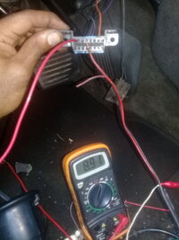
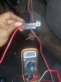
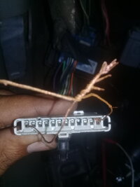
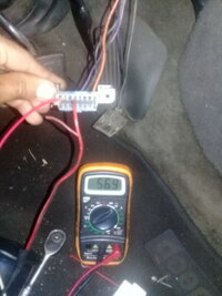
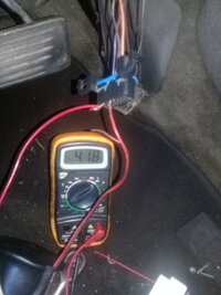
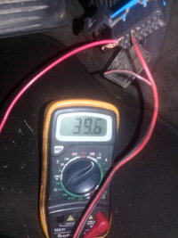
AS I suggested, at the splice pack, put a jumper in from the the PCM to the DLC pin point. AT the DLC connector, now measure the resistance at the DLC connector for the data pin USING the ground AT THE DLC connector. Report the resistance reading. Do the same test, using the BCM. And finally, do the same test with both PCM AND BCM jumpered to the DLC pin at the splice pack.
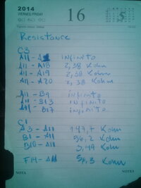
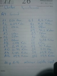
IF those report the proper resistance, you then can move on to look at the electrical conditions (voltages / grounds) at the PCM and BCM... reporting the pin that you tested and the value. Once this is done. Then measure the resistance toward the PCM and BCM for those same pins.... **** (edit- I see you have done the resistances for the PCM... not sure I found similar for the BCM).
edit NOTE: TJbaker table is in post 228 and your PCM measurements are in 244 / 248. Your data pin measurements seem high... not good.
AS I suggested, at the splice pack, put a jumper in from the the PCM to the DLC pin point. AT the DLC connector, now measure the resistance at the DLC connector for the data pin USING the ground AT THE DLC connector. Report the resistance reading. Do the same test, using the BCM. And finally, do the same test with both PCM AND BCM jumpered to the DLC pin at the splice pack.
IF those report the proper resistance, you then can move on to look at the electrical conditions (voltages / grounds) at the PCM and BCM... reporting the pin that you tested and the value. Once this is done. Then measure the resistance toward the PCM and BCM for those same pins.... **** (edit- I see you have done the resistances for the PCM... not sure I found similar for the BCM).
edit NOTE: TJbaker table is in post 228 and your PCM measurements are in 244 / 248. Your data pin measurements seem high... not good.
Last edited: