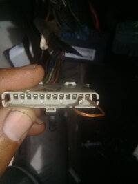
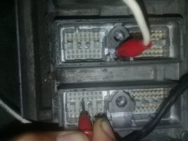
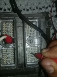
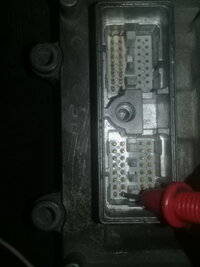
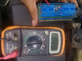
continuity line communication pcm canle dark green. It's ok
This refers to post #203
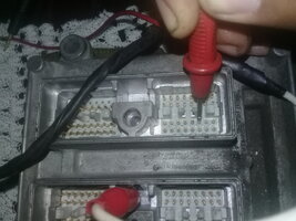
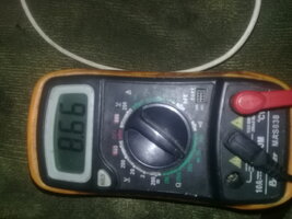
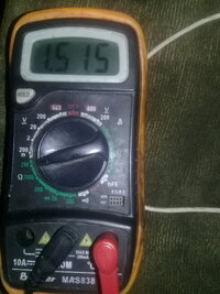
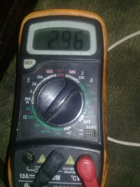
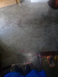
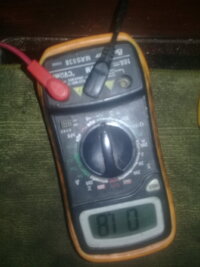
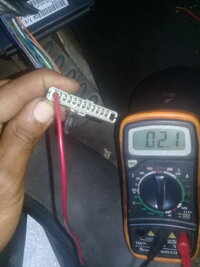
I continue to review all of this thread amd look for possible answers. In this picture, testing continuity of dark green PCM serial data wire, what is the reading on the meter? Does that read 10 ohms? Should this not read at or very close to zero ohms?
Does anyone know what would be the threshold of resistance reading on a class 2 serial data line before the signal might be attenuated enough to cause a lack of communication?
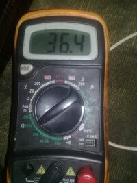

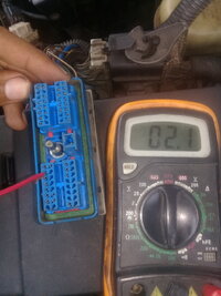


 and possibly some "finger problems" during use... for example, trying to measure resistance in a circuit that is powered. Depending on what powering is in a circuit, it may cause "internal problems" with the bridges that are used to measure the resistance. Of course, a check would be an out of circuit, free standard resistor. You know it can not change value from one range to another.