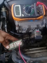
NEED HELP Unknown Driver and No Start

Mooseman

Moderator
Dec 4, 2011
26,009
Ottawa, ON
Replacing the BCM is no trivial matter. It has to be programmed with your VIN and the options in your truck, a relearn of the security must be done (it will not recognize your ignition lock sensor) which will not allow the PCM to start the engine. All this will require the use of a high-end scanner like a Tech 2.

With the BCM disconnected, if you still can't communicate with the PCM to obtain codes, it is not your problem.
 
  • Like
Reactions: TJBaker57

Mramses

Original poster
Member
Jul 19, 2020
322
17176352
Replacing the BCM is no trivial matter. It has to be programmed with your VIN and the options in your truck, a relearn of the security must be done (it will not recognize your ignition lock sensor) which will not allow the PCM to start the engine. All this will require the use of a high-end scanner like a Tech 2.

With the BCM disconnected, if you still can't communicate with the PCM to obtain codes, it is not your problem.
I understand friend then what could be happening? What do you recommend me to do now to find the solution to the problem of the truck?
 

Mooseman

Moderator
Dec 4, 2011
26,009
Ottawa, ON
Good to know you have an elm327. Have you already used the elm327 and are you familiar with any apps that work with the elm327?

Your next step should be to test one or two modules at a time. Let me explain. Your truck has at least a dozen modules. If even one of these has gone bad, that module can prevent the whole network from functioning. In order to see if there are good and bad modules you must isolate the modules and try to connect with elm327 or tech 2 one or maybe two modules at a time. To do this you must pull the 'comb' from the splice pack(s). This will disconnect the modules from each other. To test a module you must then connect the data test port (purple wire at front splice) to a single module then try to scan with elm327 and some app. I would start by connecting the purple wire to the light green wire, both of these wires are at the front splice pack. Looking at the diagram you will see that the BCM is connected to the PCM by the yellow wire, so with the purple data port wire connected to the light green BCM wire at the splice pack you will have PCM and BCM together with the data port. Remove the comb and use some small gauge wire that will not spread open the sockets. Example here...

View attachment 96625

Do you have an app that can scan for codes or something like that?

After it is jumpered like this turn the key to accesory. There will be no dash lights as that module is not connected. Use the elm327 and an app to try to scan for codes.

As already suggested above. Connect ONLY the OBD port with the PCM and try to read codes. Report your results.
 

Mramses

Original poster
Member
Jul 19, 2020
322
17176352
As already suggested above. Connect ONLY the OBD port with the PCM and try to read codes. Report your results.
understood friend. One question, at the beginning of the thread I mentioned that when turning the switch all the lights of the cluster came on, including the image of the truck with the lock and the check engine, after a few seconds the one of the lock with the truck (light) turns off and there was only the check engine.
Then I sent to review that PCM thinking it was damaged, which was not like that and rather they damaged it. When mounting this pcm, the cluster lights were turned on but then all of them went out, including the check engine.
later, I was able to get another pcm of the same year and model, when installing it turned out to do the same as my old pcm when it was good. All the lights come on and go out leaving only the check engine.
My question, why when I change the PCM, the anti-theft warning light or the image of the truck with the padlock is not lit? I should have activated the token in the antitheft cluster. That is why I suspect that the bcm is bad and therefore does not continue the security protocol and starts the truck. In fact, when disconnecting the bcm and leaving only the pcm connected, the lights in the cluster do the same without changes, only the check engine remains
 

Mramses

Original poster
Member
Jul 19, 2020
322
17176352
My measurements are in thousands! For example my light green wire registers 22,400 ohms to ground.
Good morning friend, is it possible to disconnect the bcm completely, disconnect the comb from the sp205 and make a jumper between the dark green cable and the purple cable? then connect the elm327 and try to read the ecu? is it possible to do this? should the ecu read without problems the elm327?
please help me
 

budwich

Member
Jun 16, 2013
2,175
kanata
I understand friend then what could be happening? What do you recommend me to do now to find the solution to the problem of the truck?
you have gotten "out of control". This thread started with you doing engine work and then not being able to start the engine after doing the work. You then started doing troubleshooting and moving all over the place from the engine area to inside to things like the BCM and the jumpering / comb pack in the interior which was unlikely to have been touched during your engine work. As result, instead of staying at the engine and checking things specifically associated with stuff directly associated with the engine work therein, you have been disturbing every possible component in the vehicle. You need to put back everything that you started with as a complete truck. Then you need to start from zero and observe / post some basic no start condition trouble shooting. Yes I know language is a barrier but you need to stop and make sure it is very clear what is happening at any given point otherwise you will go back down paths all over the truck chasing "phantoms".
 

Mramses

Original poster
Member
Jul 19, 2020
322
17176352
you have gotten "out of control". This thread started with you doing engine work and then not being able to start the engine after doing the work. You then started doing troubleshooting and moving all over the place from the engine area to inside to things like the BCM and the jumpering / comb pack in the interior which was unlikely to have been touched during your engine work. As result, instead of staying at the engine and checking things specifically associated with stuff directly associated with the engine work therein, you have been disturbing every possible component in the vehicle. You need to put back everything that you started with as a complete truck. Then you need to start from zero and observe / post some basic no start condition trouble shooting. Yes I know language is a barrier but you need to stop and make sure it is very clear what is happening at any given point otherwise you will go back down paths all over the truck chasing "phantoms".
I understand my friend. Is right
 

Mramses

Original poster
Member
Jul 19, 2020
322
17176352
you have gotten "out of control". This thread started with you doing engine work and then not being able to start the engine after doing the work. You then started doing troubleshooting and moving all over the place from the engine area to inside to things like the BCM and the jumpering / comb pack in the interior which was unlikely to have been touched during your engine work. As result, instead of staying at the engine and checking things specifically associated with stuff directly associated with the engine work therein, you have been disturbing every possible component in the vehicle. You need to put back everything that you started with as a complete truck. Then you need to start from zero and observe / post some basic no start condition trouble shooting. Yes I know language is a barrier but you need to stop and make sure it is very clear what is happening at any given point otherwise you will go back down paths all over the truck chasing "phantoms".
is that I continue with the same problem friend. please understand my situation
I got to the modules because the truck communicates neither with the elm327 nor with the tech 2. Nobody has helped me with my problem except here they have followed me with my search thanks to Mr. Baker and Mooseman who have been pending.
Since the truck has no communication, we have been working on the sp205 and sp306 trying to verify if they connect to the scanner as well as checking connection cables.
I mention to him to change the pcm and my problem remains the same. My question is because when I change the pcm, the anti-theft witness does not activate. Within the tests that began to find why it does not connect to the scanner, I have come this far.
I have my doubt that the bcm is faulty and prevents the security protocol and starting of the truck
That is why I believe my failure of why it does not turn on and why it appears to me UNKNOWN DRIVER, to be the damaged bcm
 

Mramses

Original poster
Member
Jul 19, 2020
322
17176352
you have gotten "out of control". This thread started with you doing engine work and then not being able to start the engine after doing the work. You then started doing troubleshooting and moving all over the place from the engine area to inside to things like the BCM and the jumpering / comb pack in the interior which was unlikely to have been touched during your engine work. As result, instead of staying at the engine and checking things specifically associated with stuff directly associated with the engine work therein, you have been disturbing every possible component in the vehicle. You need to put back everything that you started with as a complete truck. Then you need to start from zero and observe / post some basic no start condition trouble shooting. Yes I know language is a barrier but you need to stop and make sure it is very clear what is happening at any given point otherwise you will go back down paths all over the truck chasing "phantoms".
all this is frustrating, doing tests, checking wiring, verifying earths, power and not noticing changes in the search for my problem.
But I do not lose hope of finding the problem with the truck, it has to be turned on again, so I ask you for all the help you can give me
 

budwich

Member
Jun 16, 2013
2,175
kanata
you are posting extra about nothing. Answer the question. Further, mooseman posts what you need to do to start investigating the problem with the code reader (post 165). Instead of following his advice, you post about other things making this thread even harder to follow and less likely you will get further in trying to resolve your problems. I wish you the best in trying to get this truck going but don't be your worse enemy.
 

Mramses

Original poster
Member
Jul 19, 2020
322
17176352
Listen... was there "unknown driver" before you did the engine work?
yes. After the engine work they gave it to me with that fault. I turn the key to activate the fuel pump, the throttle body activates, the driver's seat controls work, the dash lights come on, only the check engine light, the exterior lights work, hvac does not work, auxiliary hvac does not work, car insurance does not work door or windows, the lower bar light does not work in prnd12, the rear door does not work, the car does not turn on and the unknown driver light appears. tech 2 does not connect, elm327 does not connect, there is power in dlc and earths 4 and 5 are ok.
When I did the test of the communication lines I found pin2 of dlc terrified, due to the ebcm module. that's why I started working on the sp and the modules.
When turning the key to on, and measure resistance between each of the cables that reach the sp205 and ground, there are some modules that open (bcm, hvac aux, radio (disconnected), tcscm)
the rest of the modules give resistors
 

Mramses

Original poster
Member
Jul 19, 2020
322
17176352
you are posting extra about nothing. Answer the question. Further, mooseman posts what you need to do to start investigating the problem with the code reader (post 165). Instead of following his advice, you post about other things making this thread even harder to follow and less likely you will get further in trying to resolve your problems. I wish you the best in trying to get this truck going but don't be your worse enemy.
I understand friend, you are right, I will organize everything and I will advance together
 

budwich

Member
Jun 16, 2013
2,175
kanata
yes. After the engine work they gave it to me with that fault. I turn the key to activate the fuel pump, the throttle body activates, the driver's seat controls work, the dash lights come on, only the check engine light, the exterior lights work, hvac does not work, auxiliary hvac does not work, car insurance does not work door or windows, the lower bar light does not work in prnd12, the rear door does not work, the car does not turn on and the unknown driver light appears. tech 2 does not connect, elm327 does not connect, there is power in dlc and earths 4 and 5 are ok.
When I did the test of the communication lines I found pin2 of dlc terrified, due to the ebcm module. that's why I started working on the sp and the modules.
When turning the key to on, and measure resistance between each of the cables that reach the sp205 and ground, there are some modules that open (bcm, hvac aux, radio (disconnected), tcscm)
the rest of the modules give resistors
look at this post... I asked a simple question... did you have the "unknown driver" before the engine work? You answer with "yes".... we have a communication / language problem. why are you answering with "YES"?
 

Mooseman

Moderator
Dec 4, 2011
26,009
Ottawa, ON
@Mramses , we need to do this ONE STEP AT A TIME. This is what YOU need to do and report back your results:

- Remove the comb from the sp205 splice pack.
- Connect with a wire ONLY the PCM and OBD port similar to this with the dark green and purple wires:
img_20200912_103252-jpg.96878


- turn the ignition key to RUN
- Connect the Tech 2 or ELM327 and try to get codes from the PCM.
- Report your results of this test ONLY

Failure to do this will result in us recommending that you seek a professional at a GM dealership and the closing of this thread. We cannot help you if you do not follow our instructions and reporting the results we are asking for.

Again, one step at a time. We have to keep it as simple as possible trying to work around the language barrier as well as possible technical barriers.
 
  • Like
Reactions: Mramses

TJBaker57

Lifetime VIP Donor
Member
Aug 16, 2015
3,178
Colorado
That is why I believe my failure of why it does not turn on and why it appears to me UNKNOWN DRIVER, to be the damaged bcm


I offer this video as evidence the "Unknown Driver" can not by itself cause a no start condition. You will see the SP205 comb is removed and there are no jumpers. Unknown driver is seen on the DIC. The truck still starts.

 
  • Like
Reactions: Mramses

budwich

Member
Jun 16, 2013
2,175
kanata
I offer this video as evidence the "Unknown Driver" can not by itself cause a no start condition. You will see the SP205 comb is removed and there are no jumpers. Unknown driver is seen on the DIC. The truck still starts.

good work... I am scared that "significant disturbance" has happened during the long effort. As suggested, go back to basics and have the OP clearly do the PCM / BCM only setup and go from the results with focus on getting some form of talking to the PCM.

TJbaker, you did a good table of the resistance measurements at the splice pack (post 157). The OP needs to do exactly the same table with his measurements to give confidence that the physical layer of the bus to devices is good.
 
Last edited:

TJBaker57

Lifetime VIP Donor
Member
Aug 16, 2015
3,178
Colorado
In the previous video you will note that the fuel gauge, oil pressure gauge, and PRND321 has no status bar. This is because all of these functions use the serial data line from the PCM to the Instrument Cluster and it is disconnected in that video.

I have a test for you. Since we are unable to connect with the ELM or Tech 2, we will use the instrument cluster as a test tool to see if the PCM is communicating.

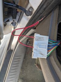
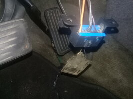
(1) disconnect the BCM data cables as shown here

IMG_20200913_105350.jpg

(2) remove the sp205 splice pack comb and jumper the dark green PCM wire to the gray Instrument Cluster wire as seen in this picture.

IMG_20200913_120346.jpg

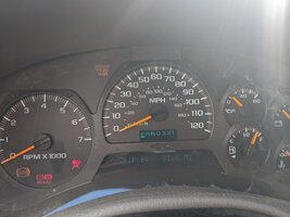
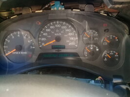
(3) turn the key to RUN and look at the cluster. Is there a status line below the P position of PRND321?? Does the fuel gauge indicate fuel level as seen in this next picture??

IMG_20200913_105426.jpg

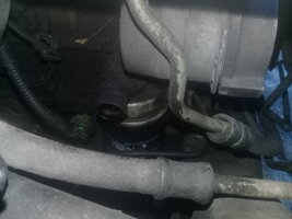
But what if the fuel level is low and the PRND321 light is broken? Here is yet another test. The engine oil pressure switch in this truck is closed circuit when there is no oil pressure and open circuit when there is oil pressure. So disconnecting the oil pressure switch simulates the presence of oil pressure.

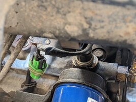
(4) disconnect the engine oil pressure switch just above the oil filter.

IMG_20200913_105656.jpg

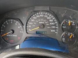
Check the gauges again with the key to RUN. Is there now oil pressure on the gauge?

IMG_20200913_105731.jpg

All 3 of these things, oil pressure, fuel level, PRND321 are sent from the PCM to the Instrument Cluster on the serial data bus. If none of this is working we must assume the PCM is not communicating and you must recheck the dark green wire from SP205 to the PCM. Also recheck all PCM connector terminal pins and recheck for power at the PCM on all PCM power sources.

If the test here above does show fuel level, oil pressure, and/or the PRND321 status bar then we conclude the PCM is communicating and the failure is elsewhere.
 
  • Like
Reactions: christo829

Mramses

Original poster
Member
Jul 19, 2020
322
17176352
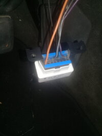
As already suggested above. Connect ONLY the OBD port with the PCM and try to read codes. Report your results.
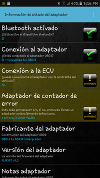
I did the indicated steps and there is no connection with elm327
 

Attachments

  • 20200913_150540.jpg
    20200913_150540.jpg
    488.2 KB · Views: 12
  • 20200913_150540.jpg
    20200913_150540.jpg
    488.2 KB · Views: 14
  • 20200913_150511.jpg
    20200913_150511.jpg
    338.4 KB · Views: 13
  • 20200913_150518.jpg
    20200913_150518.jpg
    253 KB · Views: 12

TJBaker57

Lifetime VIP Donor
Member
Aug 16, 2015
3,178
Colorado
@Mramses

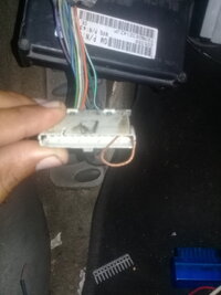
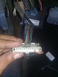
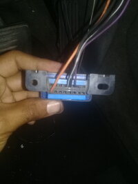
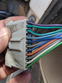
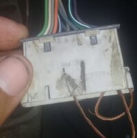
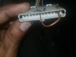
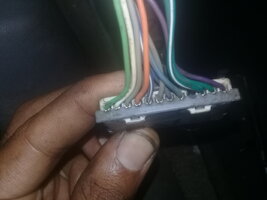
I have seen 2 pictures of your splice pack 205. In both of these pictures it cannot be seen where each wire goes. It "looks" like the wires at the purple end are not in their proper place. It could be just the picture. Can you post a picture of the splice pack from the side where we can see all of the wires and where they are oriented? Like my picture just recently that shows all the wires??
 

budwich

Member
Jun 16, 2013
2,175
kanata
mramses, note that the test tjbaker57 is referring to uses the instrument panel to help verify the operation and is not verifying that you can communicate via the odb plug.
 

Mramses

Original poster
Member
Jul 19, 2020
322
17176352
@Mramses

I have seen 2 pictures of your splice pack 205. In both of these pictures it cannot be seen where each wire goes. It "looks" like the wires at the purple end are not in their proper place. It could be just the picture. Can you post a picture of the splice pack from the side where we can see all of the wires and where they are oriented? Like my picture just recently that shows all the wires??
 

Attachments

  • 1600027811646-794072321.jpg
    1600027811646-794072321.jpg
    315 KB · Views: 10
  • 16000278330391077373535.jpg
    16000278330391077373535.jpg
    248.9 KB · Views: 11
  • Screenshot_20200913-151602.png
    Screenshot_20200913-151602.png
    337 KB · Views: 9

budwich

Member
Jun 16, 2013
2,175
kanata
mramses, one other thing when you are trying to connect with your odb interface, you have your key in ON.
 

Mramses

Original poster
Member
Jul 19, 2020
322
17176352
mramses, note that the test tjbaker57 is referring to uses the instrument panel to help verify the operation and is not verifying that you can communicate via the odb plug.
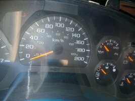
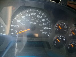
I did the test as indicated by tkbaker friend but none of the gauges are activated. Please help me. I don't know what could have happened that none of the tests are working for me. what could be wrong?
 

Mramses

Original poster
Member
Jul 19, 2020
322
17176352
In the previous video you will note that the fuel gauge, oil pressure gauge, and PRND321 has no status bar. This is because all of these functions use the serial data line from the PCM to the Instrument Cluster and it is disconnected in that video.

I have a test for you. Since we are unable to connect with the ELM or Tech 2, we will use the instrument cluster as a test tool to see if the PCM is communicating.

(1) disconnect the BCM data cables as shown here

View attachment 96925

(2) remove the sp205 splice pack comb and jumper the dark green PCM wire to the gray Instrument Cluster wire as seen in this picture.

View attachment 96926

(3) turn the key to RUN and look at the cluster. Is there a status line below the P position of PRND321?? Does the fuel gauge indicate fuel level as seen in this next picture??

View attachment 96927

But what if the fuel level is low and the PRND321 light is broken? Here is yet another test. The engine oil pressure switch in this truck is closed circuit when there is no oil pressure and open circuit when there is oil pressure. So disconnecting the oil pressure switch simulates the presence of oil pressure.

(4) disconnect the engine oil pressure switch just above the oil filter.

View attachment 96928

Check the gauges again with the key to RUN. Is there now oil pressure on the gauge?

View attachment 96929

All 3 of these things, oil pressure, fuel level, PRND321 are sent from the PCM to the Instrument Cluster on the serial data bus. If none of this is working we must assume the PCM is not communicating and you must recheck the dark green wire from SP205 to the PCM. Also recheck all PCM connector terminal pins and recheck for power at the PCM on all PCM power sources.

If the test here above does show fuel level, oil pressure, and/or the PRND321 status bar then we conclude the PCM is communicating and the failure is elsewhere.
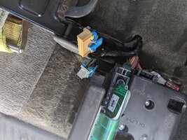
Here the test
 

Attachments

  • 1600031070447417858544.jpg
    1600031070447417858544.jpg
    953.7 KB · Views: 13
  • 1600031147867-1278391599.jpg
    1600031147867-1278391599.jpg
    356.6 KB · Views: 12
  • 1600031185396-468779240.jpg
    1600031185396-468779240.jpg
    739.9 KB · Views: 12
  • 1600031212953-1291377620.jpg
    1600031212953-1291377620.jpg
    819.4 KB · Views: 13
  • 1600031254011245710713.jpg
    1600031254011245710713.jpg
    987.6 KB · Views: 18
  • 1600031299269-1887105425.jpg
    1600031299269-1887105425.jpg
    403.1 KB · Views: 17

budwich

Member
Jun 16, 2013
2,175
kanata
try your other pcm with the same setup. The "test setup" that was suggested by tjbaker57 IS NOT the same as the test that mooseman suggested / wants. Important that you understand this? The tests jumper different pins. Post a picture of the jumper wiring that you are using to check the instrument panel as tjbaker as shown.
 

TJBaker57

Lifetime VIP Donor
Member
Aug 16, 2015
3,178
Colorado
I did the test as indicated by tkbaker friend but none of the gauges are activated. Please help me. I don't know what could have happened that none of the tests are working for me. what could be wrong?

These test results tell us the PCM is not talking. Recheck your power(s) to the PCM, I know of 4 different power inputs to the PCM. Recheck the dark green wire from splice pack to the PCM. Check very carefully all pins on the 3 PCM connectors. If everything is connected and the PCM still does not communicate it is possible the PCM is bad.
 

budwich

Member
Jun 16, 2013
2,175
kanata
hold it... the last picture shows the instrument panel with the RIGHT displays.

sorry I see there are no gages happening. follow tjbaker57 suggestion of checking for power at the pcm.
 

budwich

Member
Jun 16, 2013
2,175
kanata
follow tjbaker57's suggestion, check for power at the PCM... there is multiple pins for power .... write down each pin number / connector number that you checked and post here.
 
Last edited:

Mooseman

Moderator
Dec 4, 2011
26,009
Ottawa, ON
Along with power, also check all the grounds to the PCM.
 
  • Like
Reactions: TJBaker57

Mramses

Original poster
Member
Jul 19, 2020
322
17176352
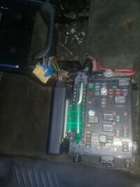
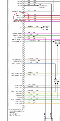
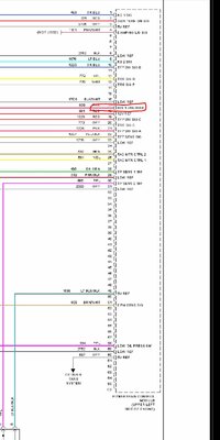
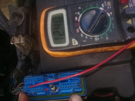
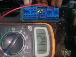
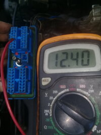
These are the 4 PCM power supplies that I am aware of. Anyone know if I am missing more?
Hello friends. power of the pcm in 3 C1 and 1 C3
 

Attachments

  • 1600283412068804112234.jpg
    1600283412068804112234.jpg
    1 MB · Views: 8
  • 1600283444281763759975.jpg
    1600283444281763759975.jpg
    387.7 KB · Views: 7
  • 1600283474669952954920.jpg
    1600283474669952954920.jpg
    341 KB · Views: 7
  • 1600283513803-1552813202.jpg
    1600283513803-1552813202.jpg
    500.6 KB · Views: 9

Forum Statistics

Threads
23,675
Posts
641,851
Members
19,113
Latest member
SCr

Members Online