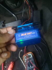
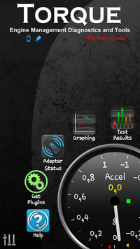
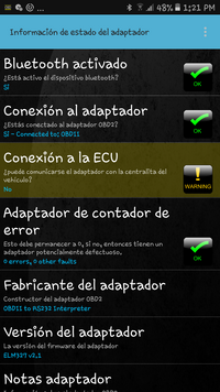
Your results with Torque Pro and Car Scanner confirm the apps are connecting to the ELM327 device but fail to connect to the PCM.
When the ELM327 tries to connect to a PCM or ECM it broadcasts a request over the network addressed to any PCM or ECM on the network. If there is no answer then the connection to ECU fails. There is no request to any other module(s) so even if the BCM and EBCM, Instrument Cluster and all the other modules are working the scanner app fails because it is only seeking the PCM/ECM.
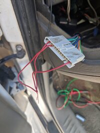
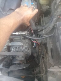
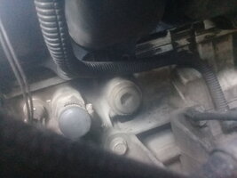
It is possible your PCM is not answering due to a PCM power connection (there are more than one and 2 of them are required before the PCM will communicate). Or it could be a fault in the serial data line to the PCM or the yellow serial data wire between the PCM and the BCM.
There is a way to use Car Scanner as a terminal and check for network traffic to and from other modules,,, but it is not automatic. The App does not do the job, the user must type in certain specific commands to attempt communication with another module.