It makes a lot of sense friend, is it possible to get the electrical connection diagrams to verify that they are connected? my tb is 2002 4x4 4.2LI just noted something in support of this idea. I was looking over the imagery to see what clues are there. I was looking for things that require class 2 connections like the temp gauge, oil pressure, fuel level. The MIL light has a direct connection so that doesn't help in regard to class 2. Same for the battery charge indicator. Then i noticed the PRND321 display. There is no indicator under any of the selections as there should be. There presumably should be a bar under P (ark). This value is sent from the PCM to the display system so the lack of that indicator suggests no class 2 communication from PCM to Instrument Cluster and possibly other modules as well.
You are using an out of date browser. It may not display this or other websites correctly.
You should upgrade or use an alternative browser.
You should upgrade or use an alternative browser.
NEED HELP Unknown Driver and No Start
- Thread starter Mramses
- Start date
So either one of two things. Power is not getting to all the modules or there is a communication problem on the network.
Try pulling the front splice pack comb and connect only the wires for the PCM and the OBD port with a small piece of wire. Try scanning with the Tech 2 again. Do the same for the BCM. Post your results.
friend the elm327 can scan the tb 2002 4x4 4.2 L? if the pcm is not the original one, you should turn on the anti-theft indicator Another question, if I turn the key to run and with a voltmeter I measure the data signal serial class 2 of the pcm and bcm, should it give me voltage 0-7 V?
understood I'm going to see it in detail friend. Thank you for being aware of my case to you and to all the colleagues of the forum.This is an excellent video on how to diagnose a module that is taking down the whole network. Although this is for a 2008, the procedure is the same. Wire colours may be different.
I'm going to do the review you recommend and upload the results
It makes a lot of sense friend, is it possible to get the electrical connection diagrams to verify that they are connected? my tb is 2002 4x4 4.2L
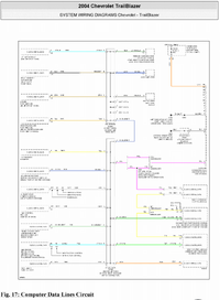
I own an 02 TrailBlazer 4.2 myself. I have noted that the 2002 wiring diagrams for the data wires seem to have one error or ommision. The 2002 diagrams fails to show the connection to the inflatable restraints on terminal F, a dark blue wire. I have found the 2004 wiring diagram matches my 2002 vehicle so I will share those here.
friend the elm327 can scan the tb 2002 4x4 4.2 L? if the pcm is not the original one, you should turn on the anti-theft indicator Another question, if I turn the key to run and with a voltmeter I measure the data signal serial class 2 of the pcm and bcm, should it give me voltage 0-7 V?
Reading voltage on the serial wires: a digital voltmeter will show some voltage but will not tell what the trouble is. The 0 to 7 volts (or more) switches too fast for the meter to react to.
Elm327: the elm327 is an adapter that allows smartphone apps to communicate with the vehicle network. There are android apps that will try to scan the vehicle for troubles, but if there is no communications they will fail just like the tech 2. One advantage of the elm327 adapters is they are fairly inexpensive so you can afford to do tests without having to wait for someone with a tech 2 or other expensive scantool. I have learned much of the language of the 2002 4.2 and know how to 'talk' to the vehicle directly so it is a very useful tool for me.
friend the truck does not bring the theft deterrent control module system. is this normal? It only brings the key sensor and the lock key sensor. TB is 2002 4x4 4.2L
My 2002 also does not have the theft detterent module. So our trucks are much the same, yours and mine.
OK friend. that you recommend me to review first with respect to my case, since when connecting the tech 2 there was no communication with pcm, bcm or abs.Reading voltage on the serial wires: a digital voltmeter will show some voltage but will not tell what the trouble is. The 0 to 7 volts (or more) switches too fast for the meter to react to.
Elm327: the elm327 is an adapter that allows smartphone apps to communicate with the vehicle network. There are android apps that will try to scan the vehicle for troubles, but if there is no communications they will fail just like the tech 2. One advantage of the elm327 adapters is they are fairly inexpensive so you can afford to do tests without having to wait for someone with a tech 2 or other expensive scantool. I have learned much of the language of the 2002 4.2 and know how to 'talk' to the vehicle directly so it is a very useful tool for me.
Additionally, the friend who runs the equipment (mechanical workshop) was not very open to opinions and gave my case as something very complicated.
I have an elm327 so I asked the question to see if with it I can verify if there is a connection with the modules. and then be able to connect the tech 2 if it were required
thanks friend
OK friend. that you recommend me to review first with respect to my case, since when connecting the tech 2 there was no communication with pcm, bcm or abs.
Additionally, the friend who runs the equipment (mechanical workshop) was not very open to opinions and gave my case as something very complicated.
I have an elm327 so I asked the question to see if with it I can verify if there is a connection with the modules. and then be able to connect the tech 2 if it were required
thanks friend
who initially governs "the permissions" to activate the PCM and the rest of the modules?My 2002 also does not have the theft detterent module. So our trucks are much the same, yours and mine.
first does the BCM receive the signal from the key? The signal from the lock key sensor must also be received by the BCM?
After this, the BCM grants the permissions to the PCM and the rest of the modules?
initially where should my search for the problem begin.
How can I check that the permission signals for the BCM are coming to authorize the PCM to activate
If voltage and ground reach the BCM module but it does not generate the permissions for the activation of the PCM, could it be faulty? How could I verify that the BCM is good, thinking that this is the main element for activating the functions of the truck and the PCM
OK friend. that you recommend me to review first with respect to my case, since when connecting the tech 2 there was no communication with pcm, bcm or abs.
Additionally, the friend who runs the equipment (mechanical workshop) was not very open to opinions and gave my case as something very complicated.
I have an elm327 so I asked the question to see if with it I can verify if there is a connection with the modules. and then be able to connect the tech 2 if it were required
thanks friend
Good to know you have an elm327. Have you already used the elm327 and are you familiar with any apps that work with the elm327?
Your next step should be to test one or two modules at a time. Let me explain. Your truck has at least a dozen modules. If even one of these has gone bad, that module can prevent the whole network from functioning. In order to see if there are good and bad modules you must isolate the modules and try to connect with elm327 or tech 2 one or maybe two modules at a time. To do this you must pull the 'comb' from the splice pack(s). This will disconnect the modules from each other. To test a module you must then connect the data test port (purple wire at front splice) to a single module then try to scan with elm327 and some app. I would start by connecting the purple wire to the light green wire, both of these wires are at the front splice pack. Looking at the diagram you will see that the BCM is connected to the PCM by the yellow wire, so with the purple data port wire connected to the light green BCM wire at the splice pack you will have PCM and BCM together with the data port. Remove the comb and use some small gauge wire that will not spread open the sockets. Example here...
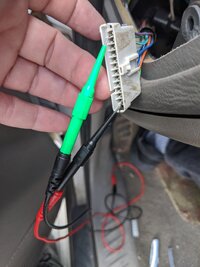
Do you have an app that can scan for codes or something like that?
After it is jumpered like this turn the key to accesory. There will be no dash lights as that module is not connected. Use the elm327 and an app to try to scan for codes.
Thanks friend I will start by verifying that each module reaches power, ground and data class 2. then verify if each module connects according to the diagram you have sent me and I will check if there is 2-7 vdc in the data serial class2 line of each module
who initially governs "the permissions" to activate the PCM and the rest of the modules?
first does the BCM receive the signal from the key?
The BCM (body control module) maintains the status of the network, however, many of the modules have power always and are just idle, in a "sleep" mode even when the key is off. Depending on how the vehicle is approached, a module will send a "wake up" message out across the network for all modules to hear. For example, If you have a keyfob with an unlock button, that signal is sent to the rear endgate module and then the endgate module sends out a wake up message and a request to the door lock to open. If you do not use the keyfob and simply open a door, then it is the body control module that wakes up the network.
Some functions depend on the key to be on.
Thanks friend I will start by verifying that each module reaches power, ground and data class 2. then verify if each module connects according to the diagram you have sent me and I will check if there is 2-7 vdc in the data serial class2 line of each module
It is very likely you will not see 2 -7 volts with a meter. A meter is too slow to read these rapidly varying voltages. You might see a very low voltage but this will only happen when there is active traffic on the network. This short video might give you an idea of what I am trying explain about the voltage. Here I am using a signal tracer that reacts to varying electrical fields. You will see and hear the rapidly changing signals that a meter simply cannot read fast enough....
New video by Thomas J Baker
 photos.app.goo.gl
Good friend thank you very much I think this test is very good. question: the elm327 you use what version is it? and has been able to connect it to the trailblazer without problems. I have 2 versions, the Bluetooth one and the usb cable version.Good to know you have an elm327. Have you already used the elm327 and are you familiar with any apps that work with the elm327?
Your next step should be to test one or two modules at a time. Let me explain. Your truck has at least a dozen modules. If even one of these has gone bad, that module can prevent the whole network from functioning. In order to see if there are good and bad modules you must isolate the modules and try to connect with elm327 or tech 2 one or maybe two modules at a time. To do this you must pull the 'comb' from the splice pack(s). This will disconnect the modules from each other. To test a module you must then connect the data test port (purple wire at front splice) to a single module then try to scan with elm327 and some app. I would start by connecting the purple wire to the light green wire, both of these wires are at the front splice pack. Looking at the diagram you will see that the BCM is connected to the PCM by the yellow wire, so with the purple data port wire connected to the light green BCM wire at the splice pack you will have PCM and BCM together with the data port. Remove the comb and use some small gauge wire that will not spread open the sockets. Example here...
View attachment 96625
Do you have an app that can scan for codes or something like that?
After it is jumpered like this turn the key to accesory. There will be no dash lights as that module is not connected. Use the elm327 and an app to try to scan for codes.
that type that connection that indicates to me you already executed it? if you connect to elm327?
Thanks friend please don't stop helping me
the application it uses is TORQUEGood to know you have an elm327. Have you already used the elm327 and are you familiar with any apps that work with the elm327?
Your next step should be to test one or two modules at a time. Let me explain. Your truck has at least a dozen modules. If even one of these has gone bad, that module can prevent the whole network from functioning. In order to see if there are good and bad modules you must isolate the modules and try to connect with elm327 or tech 2 one or maybe two modules at a time. To do this you must pull the 'comb' from the splice pack(s). This will disconnect the modules from each other. To test a module you must then connect the data test port (purple wire at front splice) to a single module then try to scan with elm327 and some app. I would start by connecting the purple wire to the light green wire, both of these wires are at the front splice pack. Looking at the diagram you will see that the BCM is connected to the PCM by the yellow wire, so with the purple data port wire connected to the light green BCM wire at the splice pack you will have PCM and BCM together with the data port. Remove the comb and use some small gauge wire that will not spread open the sockets. Example here...
View attachment 96625
Do you have an app that can scan for codes or something like that?
After it is jumpered like this turn the key to accesory. There will be no dash lights as that module is not connected. Use the elm327 and an app to try to scan for codes.
but I think the one that connects to usb uses another. Which one would you recommend me brother?
yes. The key has a remote lock / unlock control.The BCM (body control module) maintains the status of the network, however, many of the modules have power always and are just idle, in a "sleep" mode even when the key is off. Depending on how the vehicle is approached, a module will send a "wake up" message out across the network for all modules to hear. For example, If you have a keyfob with an unlock button, that signal is sent to the rear endgate module and then the endgate module sends out a wake up message and a request to the door lock to open. If you do not use the keyfob and simply open a door, then it is the body control module that wakes up the network.
Some functions depend on the key to be on.
What program do you recommend to use elm327 since I have not used it in tb. What version of the elm327 do you use?
Do you have the Bluetooth version or the usb connection version?
You are right, I will not be able to determine if any module is sending the corresponding signals. I watched the video and it's a pretty nifty tool.It is very likely you will not see 2 -7 volts with a meter. A meter is too slow to read these rapidly varying voltages. You might see a very low voltage but this will only happen when there is active traffic on the network. This short video might give you an idea of what I am trying explain about the voltage. Here I am using a signal tracer that reacts to varying electrical fields. You will see and hear the rapidly changing signals that a meter simply cannot read fast enough....

New video by Thomas J Baker
photos.app.goo.gl
in this case I hope to be able to connect to the pcm and bcm with the indications it has given me.
is there a way to check the data serial class 2 output signals without a special tool?
The point is: if I check the power, ground and data line serial class 2 connections are all ok, then should I discard the modules?9
the elm327 you use what version is it? and has been able to connect it to the trailblazer without problems.
If "what version is it" means what advertised version like 1.3 or 1.4 or 1.5 I will say almost all of these advertised numbers are false. These copies are made in china and are not true ELM327 chips. This is generally not a problem however. There is an android app called elm identifier that will test the device and report what level of commands are supported. I have 4 bluetooth models and all of mine are level 1.4.
All the USA model Trailblazers made before 2008 communicate using the SAE J1850 VPW standard, so our elm327 devices must support this protocol. I have read about some newer elm327 copies that are dropping support for J1850 since it is no longer used since 2008.
ELM327 Identifier - Apps on Google Play
Quickly identify fake or genuine ELM327 bluetooth and WIFI adapter
All 4 of my devices connect to the trailblazer OK but once in a while, if I have used the device on a different vehicle, I have needed to manually set the protocol.
This is very important so that the elm327 can work in the tb2002 I will download the application to be able to inform myself.If "what version is it" means what advertised version like 1.3 or 1.4 or 1.5 I will say almost all of these advertised numbers are false. These copies are made in china and are not true ELM327 chips. This is generally not a problem however. There is an android app called elm identifier that will test the device and report what level of commands are supported. I have 4 bluetooth models and all of mine are level 1.4.
All the USA model Trailblazers made before 2008 communicate using the SAE J1850 VPW standard, so our elm327 devices must support this protocol. I have read about some newer elm327 copies that are dropping support for J1850 since it is no longer used since 2008.
ELM327 Identifier - Apps on Google Play
Quickly identify fake or genuine ELM327 bluetooth and WIFI adapterplay.google.com
All 4 of my devices connect to the trailblazer OK but once in a while, if I have used the device on a different vehicle, I have needed to manually set the protocol.
I think the ones I have acquired are Chinese copies like almost everything.
the older the elm327 version, the more likely it is compatible
My devices are all Bluetooth models.
I use Torque Pro for many things.
I also use a simple serial terminal app where I must type commands and the responses come to the screen as hexadecimal code that I have learned to read and interpret.This is usefull for special circumstances.
Other Apps I use are Car Scanner, OBD Fusion, and Car Gauge Pro. Each of these have strong points and weaknesses.
Am I correct that you have not connected the ELM327 to the TrailBlazer at all? But you have used the ELM327 and Torque on other vehicles?
I honestly bought it for the trailblazer but so far I have not been able to connect it. I have not used it in another vehicle friend, I have only informed myself in what I found on the internet.My devices are all Bluetooth models.
I use Torque Pro for many things.
I also use a simple serial terminal app where I must type commands and the responses come to the screen as hexadecimal code that I have learned to read and interpret.This is usefull for special circumstances.
Other Apps I use are Car Scanner, OBD Fusion, and Car Gauge Pro. Each of these have strong points and weaknesses.
Am I correct that you have not connected the ELM327 to the TrailBlazer at all? But you have used the ELM327 and Torque on other vehicles?
I had the opportunity to use the op-com for an astra but I have not used for now the elm327 is a disadvantage for me but I will inform myself well to learn and be able to use it in the trailblazer, I thought it does not connect to the tb but I hope like you can connect and find the fault.
you are very knowledgeable about this subject, I will try to make the most of it, friend, I hope you have patience for my knowledge of the subject
good night friend how are you? Could you tell me where I can get the wiring diagrams of the trailblazer 2002 4x4 4.2l please?My devices are all Bluetooth models.
I use Torque Pro for many things.
I also use a simple serial terminal app where I must type commands and the responses come to the screen as hexadecimal code that I have learned to read and interpret.This is usefull for special circumstances.
Other Apps I use are Car Scanner, OBD Fusion, and Car Gauge Pro. Each of these have strong points and weaknesses.
Am I correct that you have not connected the ELM327 to the TrailBlazer at all? But you have used the ELM327 and Torque on other vehicles?
And if there is a document where it describes the location of the components, modules, grounds, power and sensors?
Mooseman
Moderator
good night friend how are you? Could you tell me where I can get the wiring diagrams of the trailblazer 2002 4x4 4.2l please?
Right here:
Need GMT360/370 Service Manuals? Get them Here!
And if there is a document where it describes the location of the components, modules, grounds, power and sensors?
Paging @MRRSM Paging @MRRSM (he has those readily available)
Right here:
Need GMT360/370 Service Manuals? Get them Here!
Thank you very much friend, good day
Paging @MRRSM Paging @MRRSM (he has those readily available)
good night friends I was disconnected because of my work and other problems. Today I started the tests of the class 2 data line. I found continuity to ground in the sp205, when disconnecting the sp205 union and testing each independent wiring, I found that the light blue line of the brake system (ebcm) gives continuity to ground or ground . it should not be like that?
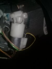
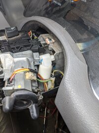
Another question, three connectors arrive at the key assembly, one that has 3 wires (yellow, white red, black orange) corresponds to the key sensor, another 2 wire connector (green, brown) lock sensor, this one does not it gives continuity when the key is on the switch (I placed it on the plan and it tells me that it is an alarm contact but when the key is there it does not close the contact between the green and brown wires, and the last 2-wire connector (yellow, black) the latter where is it connected or what function does it fulfill?
Another question, three connectors arrive at the key assembly, one that has 3 wires (yellow, white red, black orange) corresponds to the key sensor, another 2 wire connector (green, brown) lock sensor, this one does not it gives continuity when the key is on the switch (I placed it on the plan and it tells me that it is an alarm contact but when the key is there it does not close the contact between the green and brown wires, and the last 2-wire connector (yellow, black) the latter where is it connected or what function does it fulfill?
Hello Brother how are you? thanks for answering. yes, it is the same 2002Here is a better picture from my own 2002. This should be the same with better lighting
View attachment 96866
the connector with 2 wires (byellow, black) what function does it have? is it some sign of permission? it does not appear in the diagrams
Another question, the 2-wire connector (green, brown) should close the ignition when inserting the key or am I wrong?
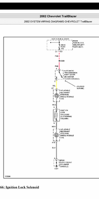
According to the diagram it is an ignition and alarm switch
Another question, I was given continuity to ground by the EBCM in the sp205 connector, the rest do not give continuity. I'm just starting with the revision that you indicated.
Another question, the 2-wire connector (green, brown) should close the ignition when inserting the key or am I wrong?
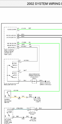
I just checked mine by probing the connector E3 at the body control module. This is where that green wire goes according to the wiring diagram. This partial diagram indicates that switch closes to ground however as I just now checked mine the behaviour is unexpected. Upon inserting the key and closing the drivers door the resistance is approximately 210 ohms and falls gradually until 113 ohms then suddenly drops. Here is a video of the aforementioned behaviour...
but the yellow black wiring is a switch or a signal? I am not very clear.View attachment 96870
I just checked mine by probing the connector E3 at the body control module. This is where that green wire goes according to the wiring diagram. This partial diagram indicates that switch closes to ground however as I just now checked mine the behaviour is unexpected. Upon inserting the key and closing the drivers door the resistance is approximately 210 ohms and falls gradually until 113 ohms then suddenly drops. Here is a video of the aforementioned behaviour...
your tests with the green wire e3 to ground, does it give you continuity when inserting the key?
and the other connector? the one with the yellow and black wire? what would be the behavior?View attachment 96870
I just checked mine by probing the connector E3 at the body control module. This is where that green wire goes according to the wiring diagram. This partial diagram indicates that switch closes to ground however as I just now checked mine the behaviour is unexpected. Upon inserting the key and closing the drivers door the resistance is approximately 210 ohms and falls gradually until 113 ohms then suddenly drops. Here is a video of the aforementioned behaviour...
the key sensor? of yellow, red-white and orange-black cables. what is the behavior?
thanks for watching my friend
the yellow black wiring is a switch or a signal? I am not very clear.
your tests with the green wire e3 to ground, does it give you continuity when inserting the key?
The yellow and black wires connect to the ignition lock solenoid. It is not a switch. It is not a signal. When the key is in RUN or START and the transmission is in Park it should have power across the yellow and black it and allows the key to be turned off. If the Transmission is not in park the solenoid is not powered and the key can not be turned to OFF.
The green wire to E3 of the BCM does NOT give continuity to ground. It gives a resistance that can be read with a test meter. The resistance lowers for 30 seconds but never did I see it go to zero ohms resistance. Maybe someone else here has an explanation, I do not currently understand it myself.
the key sensor? of yellow, red-white and orange-black cables. what is the behavior?
This is part of the security system. When the key is turned this sensor sends a signal to the BCM saying the ignitiin lock cylinder was turned with a proper key. If someone tried to "hot-wire" the car to steal it ,, this sensor would not then send the OK signal to the BCM and the engine would not continue to operate.
thanks friend. now i'm clear
which electrical wiring diagram should guide me to check TB2002? 2002 wiring, 2003 wiring or 2004 wiring?
since I downloaded the 3 but I have noticed that there are components that my truck does not bring and they are in the diagrams
which electrical wiring diagram should guide me to check TB2002? 2002 wiring, 2003 wiring or 2004 wiring?
since I downloaded the 3 but I have noticed that there are components that my truck does not bring and they are in the diagrams
To do the tests that I indicated in the previous post regarding the verification of the line data class 2.This is part of the security system. When the key is turned this sensor sends a signal to the BCM saying the ignitiin lock cylinder was turned with a proper key. If someone tried to "hot-wire" the car to steal it ,, this sensor would not then send the OK signal to the BCM and the engine would not continue to operate.
Should I only connect a jumper between the pcm and bcm on the sp205? and disconnect the sp306?
only with the connection of the pcm and bcm line class 2 should I be able to scan with the elm327? Should the truck turn on only with the pcm and bcm data line connected?
I am going to verify the power of pcm and bcm as well as the ground of these.
If I have power, ground and class 2 line data in order or ok, should I start the truck?
How could I rule out that the BCM is bad? Could the BCM not be generating the approval signal to start the truck?
Mooseman
Moderator
To do the tests that I indicated in the previous post regarding the verification of the line data class 2.
Should I only connect a jumper between the pcm and bcm on the sp205? and disconnect the sp306?
only with the connection of the pcm and bcm line class 2 should I be able to scan with the elm327?
Should the truck turn on only with the pcm and bcm data line connected?
That is all correct except you also need to jump to the OBD port to be able to scan. With those three connected together, you should be able to scan for codes and start the engine. Nothing else will work though.
If I have power, ground and class 2 line data in order or ok, should I start the truck?
Yes, it should start.
How could I rule out that the BCM is bad? Could the BCM not be generating the approval signal to start the truck?
If the BCM is truly bad, the engine will not start because the PCM is not receiving the OK to start from it.
which electrical wiring diagram should guide me to check TB2002? 2002 wiring, 2003 wiring or 2004 wiring?
For your 02, use the 02 manual. There may be some options in the schematics that may not be in your particular truck like heated seats and Bose radio and amp. Just ignore the options that you don't have.
Another question, I was given continuity to ground by the EBCM in the sp205 connector, the rest do not give continuity.
This is a major problem you should investigate further. If the EBCM or its data wire to sp205 is shorted to ground, this will prevent everything from working, including the BCM and PCM. Disconnect the EBCM at its connector under the truck and see if that line at sp205 is still shorted to ground. If not, then the EBCM is bad and must be replaced.
Thank you very much friend for responding and still being pending. thank you all for staying hereThat is all correct except you also need to jump to the OBD port to be able to scan. With those three connected together, you should be able to scan for codes and start the engine. Nothing else will work though.
Yes, it should start.
If the BCM is truly bad, the engine will not start because the PCM is not receiving the OK to start from it.
For your 02, use the 02 manual. There may be some options in the schematics that may not be in your particular truck like heated seats and Bose radio and amp. Just ignore the options that you don't have.
This is a major problem you should investigate further. If the EBCM or its data wire to sp205 is shorted to ground, this will prevent everything from working, including the BCM and PCM. Disconnect the EBCM at its connector under the truck and see if that line at sp205 is still shorted to ground. If not, then the EBCM is bad and must be replaced.
I will continue with all your instructions
If using the 2002 wiring diagram keep in mind there is connection in the splice pack under the dashboard that is omitted from that diagram. In our 2002 trucks Terminal F has a dark blue wire to the inflatable restraints module. This is not shown in the diagram.

