You are using an out of date browser. It may not display this or other websites correctly.
You should upgrade or use an alternative browser.
You should upgrade or use an alternative browser.
NEED HELP Unknown Driver and No Start
- Thread starter Mramses
- Start date


H
thanks for answering
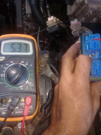
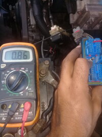
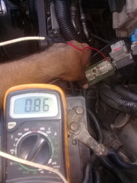
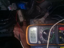
I understand my friend. I must measure resistors from C2 65 with each power input of the pcm. What values should it have?then you need to do resistance readings of those same pins on the PCM itself... that will tell if those input circuits are ok. You use the "equivalent ground of the pcm" as you tested for the ground reference for the resistance test.
thanks for answering
you compare the readings since they are all 12v inputs. Looking for unusual, open, low resistance, very high.H
I understand my friend. I must measure resistors from C2 65 with each power input of the pcm. What values should it have?
thanks for answering
resistance at C1 20 started to rise, rise and rise. C1 19 is equal to C3 17H
I understand my friend. I must measure resistors from C2 65 with each power input of the pcm. What values should it have?
thanks for answering
resistance at C1 20 started to rise, rise and rise. C1 19 is equal to C3 17then you need to do resistance readings of those same pins on the PCM itself... that will tell if those input circuits are ok. You use the "equivalent ground of the pcm" as you tested for the ground reference for the resistance test.
Attachments
-
 1600290796612828690302.jpg1 MB · Views: 5
 -
 1600290816615-342618584.jpg420.9 KB · Views: 5
 -
 1600290888013-2124770697.jpg455.6 KB · Views: 4
 -
 1600290912905391776945.jpg459.2 KB · Views: 3
 -
 16002909357551713682397.jpg417.1 KB · Views: 3
 -
 16002910156341311282290.jpg389.9 KB · Views: 3
 -
 1600291139788.png312 bytes · Views: 4
 -
 16002912002161780578261.jpg892.7 KB · Views: 4
 -
 16002912260771759245181.jpg486.8 KB · Views: 4
 -
 16002912680981740910299.jpg467.6 KB · Views: 5
 -
 16002912873751205138462.jpg407.7 KB · Views: 4
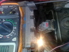
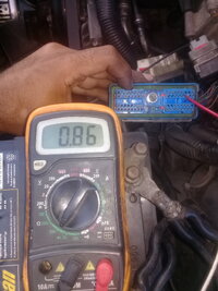
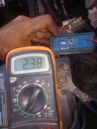
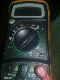
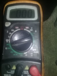
Key onwere these measured with key off or key on? this is referring to your 4 voltage measurements.
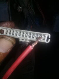
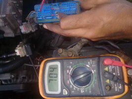
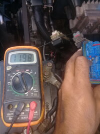
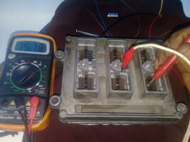
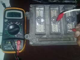
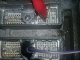
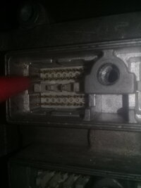
you are right... my eyes weren't looking at the full picture just the meter... dumb eyes (ass)...These look like readings of the harness connectors. Should the corresponding terminal pins of the PCM be read to confirm the PCM has no open or shorted circuit?
")
that's probably why my second request of checking the other PCM didn't make any sense to the OP, I bet...
One other thing, tjbaker57. You notice that the battery light is on in the IPC. My understanding is that gets set by the IPC based on a command from the PCM so to me that would confirm that some form of PCM comms is happening. I am thinking the rest of the problem with IPC might be with the IPC and not PCM comms to it.... maybe...These look like readings of the harness connectors. Should the corresponding terminal pins of the PCM be read to confirm the PCM has no open or shorted circuit?
but the resistance values I am measuring in the harness of the pcm. they are not connected to the pcm. that's fine?what about pin 21? sorry for the extra work. You have another PCM... right? you don't have to install it but do the same resistance measurements on that one also.
How should I do the measurement?These look like readings of the harness connectors. Should the corresponding terminal pins of the PCM be read to confirm the PCM has no open or shorted circuit?
connected the harness to the pcm and connected the battery?
One other thing, tjbaker57. You notice that the battery light is on in the IPC. My understanding is that gets set by the IPC based on a command from the PCM so to me that would confirm that some form of PCM comms is happening
Well I'm not certain of all the inner workings but I just now confirmed that with my sp205 comb removed I still have that battery indicator (the charge indicator as called in the charging circuit diagram). And it remains lit after starting the engine with the comb removed. The cluster does get a voltage signal on the class 2 network to drive the voltmeter. As you may remember I have a thread on reading the class 2 serial data.
How should I do the measurement?
connected the harness to the pcm and connected the battery?
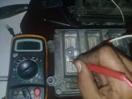
Read from the pins of the PCM to the ground terminal on the PCM. The idea is to confirm the PCM circuits are correct inside the PCM
Do you mean that the cluster may be damaged?One other thing, tjbaker57. You notice that the battery light is on in the IPC. My understanding is that gets set by the IPC based on a command from the PCM so to me that would confirm that some form of PCM comms is happening. I am thinking the rest of the problem with IPC might be with the IPC and not PCM comms to it.... maybe...
this pcm is the one that does not turn on the check engine light. before if I did, then they damaged it trying to find my problem
Attachments
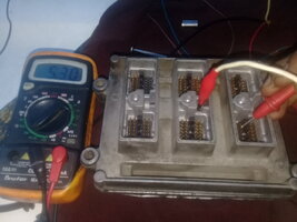
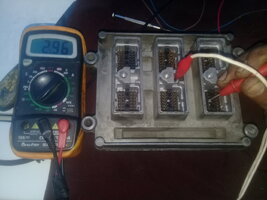
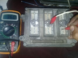
this pcm turns on the check engine and c1 21 has a resistance value of 1570000 ohm
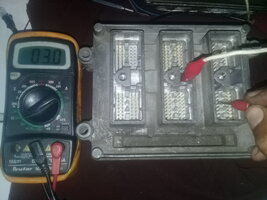
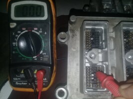
in both pcm it gives me 0 ohm in c3 17. is that normal?
in both pcm it gives me 0 ohm in c3 17. is that normal?
Attachments
do this same test with the one that is currently bolted in the motor. The "zero" doesn't look good.this pcm is the one that does not turn on the check engine light. before if I did, then they damaged it trying to find my problem
Ignore my post.
As I indicated and perhaps expected, that some resistance readings should be "normal" (ie. not zero, not infinity, and maybe not high high). i would expect both units to have similar "powering circuitry" connected to incoming power... yet I know nothing of the actual circuit itself. I don't think it matters... maybe. The zero does not look right and potentially is the problem although I would have expected that to blow a fuse on the IGN 1 fuse protection.
Of course, if we had a known good PCM, we could check those...
Of course, if we had a known good PCM, we could check those...
sorry... you are correct, I see further that the IPC also has a check of battery voltage and does something although my "read" seems to indicate it is based on either PCM OR BCM confirming but maybe GM SI isn't as "clear" as it could be.Well I'm not certain of all the inner workings but I just now confirmed that with my sp205 comb removed I still have that battery indicator (the charge indicator as called in the charging circuit diagram). And it remains lit after starting the engine with the comb removed. The cluster does get a voltage signal on the class 2 network to drive the voltmeter. As you may remember I have a thread on reading the class 2 serial data.
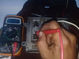
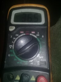
make sure you doubly confirm that you are on the right pin...Can you appreciate well the values of the resistors on the 4 power pins?
in both pcm c3 17 is grounded.
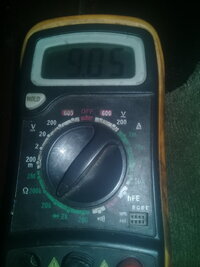
and c1 21 is 1.5 Mohm check engine
c1 21 is 300000 ohm without check engine
Updated 20200917: The image attached contains an error. I was on the wrong pin for C1, #59. The correct value is 4.66k
Here is what my results are.... Mine is also a 2002 PCM.

Here is what my results are.... Mine is also a 2002 PCM.
Last edited:
the pcm that turns on the check engine was sold to me as good second hand.As I indicated and perhaps expected, that some resistance readings should be "normal" (ie. not zero, not infinity, and maybe not high high). i would expect both units to have similar "powering circuitry" connected to incoming power... yet I know nothing of the actual circuit itself. I don't think it matters... maybe. The zero does not look right and potentially is the problem although I would have expected that to blow a fuse on the IGN 1 fuse protection.
Of course, if we had a known good PCM, we could check those...
could that be my problem? Is it possible to check that it is faulty in the internal circuit of the pcm at pin c3 17 to ground c2 65?
Can any of your colleagues make these measurements for comparison please?
Mr baker could you help me to check if those measurements are good? although already my friend Budwich (whom I thank for continuing to help me with my problem)
What should I check the wiring circuit that feeds c3 pin 17 that may be causing the failure for the pcm in case I find another pcm?
help friends
this pcm is the one that does not turn on the check engine light. before if I did, then they damaged it trying to find my problem
I am unsure which pins are being tested in these photos. I will need to look further at these...
i checked both pcm. both in C3 color TAN, pin 17make sure you doubly confirm that you are on the right pin...
Attachments


I am unsure which pins are being tested in these photos. I will need to look further at these...
Attachments
-
 16002985283801082610795.jpg474.2 KB · Views: 4
 -
 16002985848581826687589.jpg405.1 KB · Views: 4
 -
 1600298604531688991142.jpg1.1 MB · Views: 4
 -
 16002986479581635143564.jpg368.7 KB · Views: 3
 -
 1600298699477-307761447.jpg1.1 MB · Views: 3
 -
 1600298719070-1049911046.jpg440.9 KB · Views: 3
 -
 16002987548482070464268.jpg1 MB · Views: 3
 -
 1600298773712-1679004729.jpg293.4 KB · Views: 3
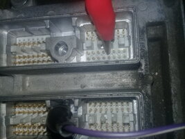
This here is on pin 22!!
View attachment 97040
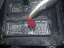
And this 'looks' like it on two pins...
View attachment 97041
result from C3 pin 17pcm no check engine
infinite resistance ohm
pcm check engine resistor 36300 ohm
Several of your pictures show you mistaken about the pin number. I suggest to recheck and be certain of the pin number you are on. Also check with the polarity reversed. Compare to my working PCM. Also,, use the smallest range of the meter that will give a result. This will mean using different meter ranges on different pins.


