ENGINE SWAP: 2004 for 2002 GM ATLAS 4.2L MOTOR

mrrsm

Original poster
Lifetime VIP Donor
Supporting Donor
Member
Oct 22, 2015
7,639
Tampa Bay Area
All Right… I've had a chance to catch some much needed 40 Winks of sleep and rested long enough to get the swelling to go down in The Ol’ Left Leg… and so here comes Part Two of the Design, Pre-Fitting and Building of the Framing for “The Franken-Oiler Machine”:

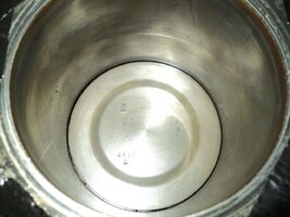
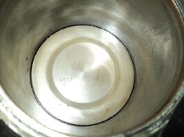
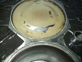
I’ve added some additional images that better capture the appearance of the features I was counting on the Aluminum Racing Fuel Cell to have and I was not disappointed in the least with what I found. When the unit arrived… I checked it over and found inconsequential damage to it in the form of a few of the four soft Aluminum Mounting Tangs that were bent a little bit… but nothing such that it compromised the integrity of the Main Container. This may explain why I was able to get it at such a low price with free S&H. No Problem. And just as I suspected… Dwelling deep inside the inner hollow cavity was a Thick, Strong Black Piece of High Tech, Fuel Resistant Cellular Foam in the dimensions of 2.5” X 11” X 11”.

THIS Sh*t... is some Very Tough Stuff!

The Foam Plank was lodged in the bottom of the tank and hanging on inside like an Alabama Tick… well out of the reach of my fingers and most other common Pliers-Type Tools, And so I resorted to my redoubtable $2.00 Harbour-Freight Extra Long Stainless Steel Haemostat… and using much more force to extract it than you might imagine necessary, I gradually coaxed that Damned Difficult Thing up and out through the Filler Neck.

I was surprised at how incredibly resistant to tearing this stuff was… but I suspect it was placed in there to assist in the reduction of “Fuel Slosh” and to eliminate any chance that any Racing Fuel would accidentally mix with any Fuel Vapours and bubble along with the outflow stream via the two Out-Flow Connectors welded into the lowest areas of the tank bottom and cause fuel starvation in a Racing Engine. But it certainly has no place being in there NOW and would have been a serious impediment to the Flow of Oil coming out of a Filled Tank.

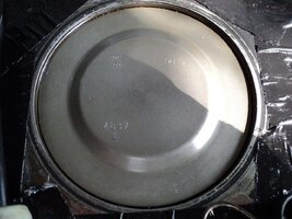
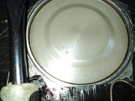
Nonetheless...THIS Container serves all of our purposes to a “T” and is the very thing we need in this case because once vacated of the Foam Plank, you can see very “Well” down inside the entire tank for inspection and cleaning prior to use. If you take notice from the images how the lower tank is bevelled down via a nice sloping angle, you can see that this will guarantee almost every single drop of either Cleaning Solution or Oil fluids can drain out of the tank completely and this serves our purposes very well for the Gravity Feed output of Engine Break-In Lubrication into the 12 Volt Electric Oil Pump.

I wanted to mention a Safety Issue concerning an artefact of using the 7” Harbour Freight Chop Saw- Angle Grinder that you will have to be aware of if you are using it for cutting Angle Iron. Ordinarily... when using either a Fine Tooth Hack-Saw or similar File Type Metal Cutting Tool… the particulate residue from these “partings” would be as fine as Beach Sand and represent no immediate danger; unless exposed to a Pure Oxygen environment where the Fine Iron Filings could spontaneously combust into a violent hot flame... You can actually see a dramatic demonstration of this happening at 25:20 onwards during this video:


But in this instance… the HF Chop Saw creates “Little Razor Blades” along the margins of every cut that are substantially large, strong and capable enough to slice swiftly through your fingers to the bone and could very easily sever skin, tendons and nerves there like they were nothing. I took a few images of these items so you will know what to watch out for and remove them to the trash before being tempted to run your hands and fingers over the freshly sawed edges of each piece of Angle Iron.


The previous entry covers the day’s efforts as far as how to quickly and efficiently Measure, Align, Cut and Drill each pairing and meeting points for the Framing Pieces to make your life easier… and trust me on this...the very last thing you want to have to do is try to prepare Angle Iron Segments to work well enough to guarantee that “ ...everything is Quite Correct” and plumb when finally assembled. This is quite simply impossible to accomplish when the pieces are randomly drilled without being deliberately associated one to the other when laying on the driveway!

First...Square the pieces as sub-assembly groups using the Carpenter's Square while arranging the Work Pieces around for convenience on top of the edges of the Portable Work Table and fix their positions with the Carpentry Clamps to hold everything in place during the cutting and drilling phases. Next...Do the Fitting and Fastening of them together at Pure Right Angles starting with the Left and Right Upright Support Segments is Half the Battle. Then its just a matter of creating sections with lengths of the proper width for the Rectangular Shelving Supports that can easily be added, once you determine how deep they will need to be and how many shelves you require for The Stand.

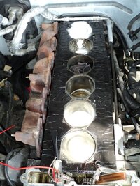
Earlier this evening… the two Valve Roller Rockers and the Kent-Moore EN-47945 Valve Spring Compressor Tool arrived...(see the attached imagery)… and as soon as the single Valve Lash Adjuster I ordered does too, I’ll attend to swapping out those components at the position between Cylinders 4 & 5 of the Intake Camshaft “Problem Lobe”. It has been a good and productive day...moving things closer and closer to the Engine Install Date. “The FrankenOiler Machine” will go a long way towards making this happen successfully.

More to Follow...

DSC07011.jpg DSC07012.jpg DSC07013.jpg DSC07014.jpg DSC07015.jpg DSC07016.jpg DSC07017.jpg DSC07018.jpg DSC07019.jpg DSC07021.jpg DSC07022.jpg DSC07023.jpg DSC07025.jpg DSC07027.jpg DSC07032.jpg DSC07040.jpg DSC07052.jpg DSC07061.jpg DSC07068.jpg DSC07085.jpg DSC07088.jpg DSC07089.jpg DSC07090.jpg DSC07091.jpg
 
Last edited:

mrrsm

Original poster
Lifetime VIP Donor
Supporting Donor
Member
Oct 22, 2015
7,639
Tampa Bay Area
Okay… Against my better judgement, I thought I could pull two tours outside in as many days in the Garage and Yard working in the Florida Heat… but this effort proved the expression “The Dog Days of August” needs no further explanation. I was only able to finish the opposing Right Upright (on YOUR right as you face the Machine) and as I was fortunate enough to have just enough Gas left in the Ol’ Tank to finish that. While I was working I had a few important “Whoa” Engineering Re-Think Moments that have made me re-evaluate this design and construct. If you’ve seen my previous similar build of the “The FrankInjector Machine” you will observe some repetition of certain features on that highly narrow and vertical design with light weight EFI Cleaning Fluids inside of a slender 90 PSI Aluminum Cylinder that even loaded to the Gunnels with all the requisite EFI harness, Fuel Rail and EFIs too, etc… is in no danger of "Falling Down"

But I realized that in addition to the extra weight in the crossing Angle Iron Pieces along with the fairly light Aluminum Oil Hopper… when filled with 2.5 Gallons of Mobil 1 along with Break-In additives… at 1.8 Lbs per quart for Mobil1 10W-40 Motor Oil… The lubricant alone will weigh in at around 18 Pounds. My concern is that if the Oil Hopper along with the Brass adaptive hardware with the hosing and the external Oil Filter, Electric Oil Pump and Modified ATX Power Supply ...even with some of those components installed lower down on the Angle Iron Frame… any support shelving sitting right at about One Foot forward of the Center Line of the Main Uprights will have a big tendency to lean and be off-centre causing weight and balance issue… and so there is a very real chance that if it either got bumped, pushed or leaned upon… the whole apparatus might easily tip over.

I know… I realize that the common Architectural Principle where the Maximum Height of a building becomes an issue and a concern is defined in the Golden Rule as:

“The Height of ANY Vertical Structure should not exceed 7 Times the Length of its Baseline..."

So a 7 to 1 Base to Height Ratio will prevent buildings of concrete and steel built within those height restrictions from tumbling down under normal stresses of the Rotation of the Earth...Wind and Storm and the twisting and torquing the building itself as it has enough “give” built in to its Margins of Safety to stand and stay there under normal “Skyscraper Loads”. But the Right Angle measurement shown in the front to back a 24” Square Baseline vs. a 44” Maximum Stand Height is MUCH less of risk; especially if outer cross plates were attached to the ends of the Angle Iron “Feet” at the Four Corners of the Base.

Nonetheless… I think my solution will be to come up with a clever way to “shelve” the 12” Square Base of the Oil Hopper and Hardware so that it sits equidistant, level and centered fore and aft… Left and Right ...so tipping will be less likely occurrence on a 24” Square Angle Iron Frame to be equipped with Cast Iron- Ball Bearing Casters that can be moved around without a great of delicacy needed to keep it upright and sound. Well... I need to get some sleep since I missed out on slumber all last night. And I’ll probably have to sleep in pretty late tomorrow to recover a bit better. Here is what I managed to finish today….

More to Follow...

DSC07092.jpg DSC07095.jpg DSC07096.jpg DSC07097.jpg DSC07098.jpg DSC07099.jpg DSC07102.jpg DSC07104.jpg DSC07105.jpg DSC07106.jpg DSC07107.jpg DSC07108.jpg DSC07109.jpg DSC07111.jpg DSC07113.jpg DSC07115.jpg DSC07116.jpg DSC07117.jpg DSCNEWSHRUNK1.jpeg DSCNEWSHRUNK2.jpeg

 
Last edited:

mrrsm

Original poster
Lifetime VIP Donor
Supporting Donor
Member
Oct 22, 2015
7,639
Tampa Bay Area
Okay... Today's Work is an extension of the last entry...so I'll take pity on my audience and keep the "Verdant Verbiage" shorter than my neighbour Gary's lawn...and speaking of him... after finishing up with all of the Final Measurements, Angle Iron Cuts and Post-Fitting and Bracing of the "Franken-Framer" portion of "The Franken-Oiler Machine" LOL.. I am truly astonished to discover that, almost to within the last Inch...all of that Angle Iron he gave to me wound up being Just Enough Material to do the Entire Job!...Man... You Gotta LOVE That! FWIW... Following the below suggestions will help you from tear-assing through a [Frame-Up] Construction that winds up becoming as Rickety and Unstable as "Lemony Snicket's Mansion":

This list represents "Bobby's Baker's Dozen: The Basics for Building ANYTHING":

(1) Use the KISS Principle when Planning and Designing ANY Damned Thing!
(2) Design EVERYTHING with the X,Y and Z Axis in Mind and Make them PLUMB!
(3) Use the Right Materials and Tools for the NEED!
(4) Break up the Construct into Discreet X,Y & Z Based ... SIMPLE, MODULAR SECTIONS!
(5) Measure THREE TIMES & Investigate all THREE Vectors: MARK THINGS CLEARLY!
(6) Pre-Fit ALL OF THE RAW PIECES BEFORE You CUT or DRILL ANYTHING!
(7) Buy 2Xs as Many FASTENERS as you THINK You will need and it will come out RIGHT!
(8) USE A 7" ANGLE GRINDER FOR METAL... NOT A 4"... The Disks Burn Out 2 SOON!
(9) Use a Carpenter's Square to Investigate ALL 45 Degree Angle Mate Up Points...X,Y&Z!
(10) Assemble EVERYTHING Loosely & DON'T TIGHTEN ANYTHING UP COMPLETELY!
(11) After Pre-assembly... Use The Carpenter's Square From the TOP DOWN!
(12) Tighten From The Top to Bottom & STAND "IT" UP. "IT" Should Sit Level, Flush & SOLID!
(13) TAKE PITY ON YOUR NEIGHBOURS & DON'T USE POWER TOOLS AT 6 AM!


As the Manager of the Cleveland Indians in the Movie, "Major League" Lou would be watching me from Heaven right about now and saying, "It's Startin' Ta Come Tagether, Pepper... Startin' Ta Come Tagether!"

PS... The Two Valve Lash Adjusters I ordered as OEM New Off of eBay arrived last night... BUT.... They Look Suspiciously "Chinese"...and They seem to have WEAR MARKS ON THEM... So I'll investigate this matter later on 'cause ...Right Now "The Florida Heat... has Made Me Feel BEAT!" and I need a Sit Down...More to Follow...


DSC07167.jpg DSC07166.jpg DSC07165.jpg DSC07164.jpg DSC07163.jpg DSC07161.jpg DSC07160.jpg DSC07159.jpg DSC07157.jpg DSC07156.jpg DSC07154.jpg DSC07153.jpg DSC07152.jpg DSC07150.jpg DSC07149.jpg DSC07148.jpg
 
Last edited:

mrrsm

Original poster
Lifetime VIP Donor
Supporting Donor
Member
Oct 22, 2015
7,639
Tampa Bay Area
I wanted to get this Rare GM Atlas 4.2L Vortec Engine Timing Chain Replacement Technician Training Video posted this evening as a separate entry... because if it comes down to cases and I have to do the New Head Swap soon after I check out the Sketchy Wear in the #4 & #5 Intake Camshaft Lobe area, caused by finding too much localized damage there, having this unusual, topical video now will help everyone unfamiliar with what the GM Atlas 4.2L Engine looks like without the Front Timing Cover installed will give us all a clear view of what is generally impossible to see without the Crankcase-Oil Pan removed from the Engine as well.

@Mooseman and @therealsethallen are a few of only a handful of Members with direct experience with doing this difficult in-vehicle repair. Ergo... I am recommending that whenever Rare GM Repair Video Gems like this become available... Downloading and saving them on your Hard Drives is not a bad idea... Every Little Bit Helps... And you never know when you might need to refer to such visual information:


Published on Jul 22, 2016

1- Install J 44221 with the camshaft flats up and the number 1 cylinder at top dead center. The crankshaft pin should be at 12 o'clock when the number 1 piston is at top dead center.
2- Compress the tensioner and lock in place.
3- Install the crankshaft sprocket.
4- Install the intake camshaft sprocket into the timing chain.
5- Align the – dark link of the timing chain with the timing mark on the intake camshaft sprocket (1).
6- Feed the timing chain down through the opening in the head.
7- Install the timing chain onto the crankshaft sprocket. Align the – dark link of the timing chain with the timing mark on the crankshaft sprocket (2).
Important: It may be necessary to temporarily remove J 44221 to rotate and hold the camshaft (hex) to align the pin to the camshaft sprocket.
8- Install the intake camshaft sprocket onto the intake camshaft.
9- Install the intake camshaft sprocket washer and new bolt.
Tighten
a. Tighten the new intake camshaft sprocket bolt the first pass to 20 Y (15 lb ft).
b. Use J 45059 to tighten the intake camshaft sprocket bolt the final pass an additional 100 degrees.
10- Install the exhaust camshaft actuator into the timing chain.
11- Align the – dark link of the timing chain with the timing mark on the exhaust camshaft actuator (1).
Important: It may be necessary to temporarily remove J 44221 to rotate and hold the camshaft (hex) to align the pin to the camshaft sprocket.
12- Install the exhaust camshaft actuator onto the exhaust camshaft.
13- Install the new exhaust camshaft actuator bolt.
Tighten
a. Tighten the exhaust camshaft actuator bolt the first pass to 25 Y (18 lb ft).
b. Use J 45059 to tighten the exhaust camshaft actuator bolt the final pass an additional 135 degrees.
14- Unlock the tensioner.
15- Remove J 44221.


Last edited:
  • Like
Reactions: therealsethallen
Sep 20, 2015
501
Western Mass.
I would have torn down and rebuilt my core motor. But when we got it out, we stuck it on wood blocks, and it fell over, shattering the coolant inlet. I did take off the front cover and to be honest it didn't look too bad.
 
  • Like
Reactions: mrrsm

mrrsm

Original poster
Lifetime VIP Donor
Supporting Donor
Member
Oct 22, 2015
7,639
Tampa Bay Area
@m.mcmillen 's recent work with replacing all of his Valve Lash Adjusters and Roller Rockers on his GM Atlas 4.2L Engine was prescient in the aspect of our mutual concern about the VLAs (Valve Lash Adjusters) being strictly AC-Delco. He kindly advised me with the correct Part Number for this weird little "Pinkie Finger Sized Push-Rod" and since the Pair Set I had ordered off of eBay came here inside a non-descriptive...non OEM Plastic "Dope Baggy" with the Model P/N written hastily along the bag surface in Black Magic Marker Ink... and it made me worry enough about their origins to head right back to eBay to seek out obtaining several more with less specious earmarks.

Alas... I went with an eBay Vendor who sported the "Genuine AC-Delco" Logo... and instead of reading the 'Very Fine Print" way down on the bottom of the Last Page... I pulled the trigger instinctively and sure enough...when these two VLAs arrived in a remarkably similar 'Dope Baggy' ...I examined them VERY carefully and found that the "I" (I-Beam Image) stamp-forged into their bases...were actually "Double-Stamped" and slightly misaligned, too!

Not being an actual "Glutton for Punishment" (although my recent absence might indicate otherwise...) I am now determined to find a source that will send me two of these damned nuisance little pieces of hardware nested inside of a TRUE OEM package. So if anybody has a particular favorite GM Licensed Vendor that they'll share the information about them with me... I'd appreciate the help.

I've been continuing to work on "The Franken-Oiler Machine" and came across a piece of 5/8" OD Heavy Duty Copper Pipe that I've had sitting way up top on a shelf in my garage for nearly 25 years and never had a reason to pull it down and look it over for any of my prior "Projects". Until NOW. Since over the years, my experiences with problematic HVAC Repairs have taught me that all of my HVAC Tools must always be The Best That $$$ Can Buy... I thought I'd use one of them here by removing one of the two (2) Lower AN-10 Compression Fitting/Plugs from the Dual Drain Ports out of the bottom edges of the Break-In Oil Hopper and use my sturdy Tubing Flare Tool to slide in a section of the 5/8" Copper Pipe and create a decent 45 Degree Angle Flare and make better use of that AN -10 Plug to suit our purposes than strictly as a "Block Off Plug".

It might seem a bit extravagant to go to so much trouble... but "The Method to My Madness" in this case involves my efforts to ensure that NO AIR Bubbles form inside the column of Break-In Oil and Additives on their way down from inside the Oil Hopper and then into a short section of 3/8" Clear Vinyl Draw Tube into the 12 Volt Oil Pump. I am counting on the vibration of the pump itself where it will be attached to the "Franken-Framer" LOL and allow any in-dwelling Air Bubbles to vibrate a bit and then boil upwards via the large, patent free space inside of the Copper Tube before being vacuumed along with the Oil Stream. It certainly won't hurt to be careful by doing this extra step. Anyway... while I am waiting for some 3/8" NPT to 3/8" Flair Brass Fittings to arrive...here is the work done to date:

More to Follow...

DSC07169.jpg DSC07171.jpg DSC07172.jpg DSC07173.jpg DSC07175.jpg DSC07176.jpg DSC07177.jpg DSC07178.jpg DSC07179.jpg DSC07180.jpg DSC07181.jpg DSC07182.jpg DSC07183.jpg
 
Last edited:
  • Like
Reactions: MAY03LT

mrrsm

Original poster
Lifetime VIP Donor
Supporting Donor
Member
Oct 22, 2015
7,639
Tampa Bay Area
Okay… After sorting out the Nightmare “Brass and Plumbing Side” Parts, Pieces and Layout to a Fair-Thee-Well… I was suddenly taken with a hunger so extreme just a few minutes ago that I could have “Eaten a Baby’s Butt Through a Park Bench”… and for whatever this recipe is worth… I threw it together the following items into a HUGE Corel Bowl...

(1) Can of Libby’s Cut Green Beans
(1) Can of Libby’s Sliced Carrots
(2) Cans of Large Mushrooms
(1) Dousing of Garlic Powder and Ground Pepper
(3) Thinly Sliced Butter Paddies (‘I Can’t Believe its NOT Butter’)
(1) A Driizzle-Schpritz of Extra Virgin Olive Oil
(1) Spreading of Mixed Cheeses

… after Nuking them for Three (3) Minutes in the Micro-Wave and wolfing it all down… I’m FULL and I’m starting to come back to life again… I know its OT… But after sorting out what you’ll see as Great Progress towards completing “The Franken-Oiler Machine”... I doubt that anyone will find fault. Besides… it gives me the chance to mention here that Mushrooms and Green Beans have the Lowest Level of Carbs of ANY foods… and trust me… blended together, this combo makes for such a very nice, high fiber meal… and so with all that culinary art mentioned… on to the business at hand:

Trying to combine the Mixed Plumbing Metaphors that you will see taking shape as the means to both deliver the nourishment of Break-In Oils and Additives… AND … be able to watch how much the Oil Pressure levels attain while the Electric Oil Sump Pump is running proved to be quite a challenge. Its safe to say that I must have used 50 sub-assemblies and pre-arranged pieces to meet the demands of the M16X1.5MMXNPT 3/8”X 28 TPI Adapter that is the Go-Between Brass Fitting to be threaded into the Oil Galley Hole in the Front of the Oil Filter Manifold of the GM Atlas 4.2L Engine.

But that was but a small part of trying to dope out the Intermediate Hosing that must be followed as the pattern to use if your intention is to build your own version of “The Franken-Oiler Machine”. It all starts with loading the Oil Hopper with the Break-In Oil and Additives and either shaking the contents or stirring them all up to form a great mix of these lubricants to ensure an even distribution of the mixtures on, in and around every critical area inside of your engine. Some variation is possible in using this Flow Pattern Design… But if you want to ensure that your actions don’t wind up causing more harm inside the engine than good… I wouldn’t deviate too much from this one:

Gravity Feed From:
Aluminum Oil Hopper…
5/8” Copper Elbow Pipe…
3/4” Clear Acrylic Tube…
1/2” 304 S/S NPT to 3/8” NPT Barbed…
3/8” Clear Acrylic Tubing in…

Gravity Input Feed TO the 12 Volt Oil Pump:
3/8” Clear Acrylic Tubing INLET Side…
12 Volt Oil Pump SUCTION SIDE…
3/8” Clear Acrylic Tubing OUTPUT Side…

Pressurized Oil Filtration @ 14 Gallons Per Hour Section:
Unfiltered Hopper Break-In Oil In……
3/8” Clear Acrylic Tubing to INPUT Side 3/8” Barb Fitting…
3/8” Clear Acrylic Tubing from OUTPUT Side 3/8” Barb Fitting…
Filtered Hopper Break-In Oil READY FOR PRESSURE OUTPUT…
3/8” Braided Nylon Tubing Pressurized Feed Line OUTPUT…
CONNECTED TO BRASS MANIFOLD via 3/8” Barb Fitting…
Linear Connection to M16X1.50XNPT 3/8” Threaded Male to Female Fitting…

Engine Block Interface:
3/8” Braided Nylon Tubing Male Threaded to the M16X1.50MM Oil Galley Adapter…
Male Threads into Oil Galley Port… PRESSURIZED BREAK-IN OIL ENTERS THE BLOCK.

Oil Pressure Gauge Interface:
The BRASS MANIFOLD requires a 1/8” NPT to 1/4” NPT to 5/16” NPT to 3/8” Set of Adapters (Whew… Yeah…What a NUISANCE.. That’s what I thought, too) to allow for the 1/8” Copper Tubing Line to be attached. This final small diameter line supports the attachment of a Lighted, Analogue 0-100 PSI Oil Pressure Gauge…. I’m undecided whether or not to add an additional OPG at the back of the block.

Now I realize that in some of the prior images, I showed the later version of the Fuel Oil Filter Unit that features an easier to change out, Screw On Style Oil Filter. But I have to be very careful NOT to Over-Pressurize any of the Internal Oil Galleys or Aluminum Block Castings and risk Cracking The Engine Block with the incompressible Break-In Oil. However… with the fact that the 12 Volt Oil Pump outputs a maximum volume of 14 Gallons Per Hour… and the Earlier Style Oil Burner Filter is rated to a filtration rating slightly above that at 15 Gallons Per Hour with a Maximum Filter Cannister Pressure of 50 PSI... that amount of Oil Volume translates to be a modest 0.02 Litres Per Minute and that does not seem to be too threatening.

Nonetheless… I will be watching the Oil Pressure Gauge with my Finger on the On-Off Switch ...Just in case I’ll need to Throttle the 12 Volt Oil Pump to keep things within 30-40 PSI. And so...I thought I would start by using First Edition of this Oil Filtration Unit first. Both Filtration Manifolds have Dual 3/8” Barbed Inlets and Outlets… So if needs be… I can easily Exchange the two designs if necessary in the future. There are 41 Images to this Photo-Play layout so I’ll have to deliver them in two parts… with a necessary 10 Minute interlude between them:

I'm in FULL AGREEMENT with @MAY03LT when it comes to NEVER THROWING AWAY PARTS THAT CAN BE USEFUL LATER ON... The FEET imaged below were salvaged from a Broken Down Washing Machine and will find new utility as Skid Pads under all Four Corners of "The Franken-Oiler Machine"

More to Follow with Component Assembly on the “Franken-Framer”… Next…

DSC07195.jpg DSC07194.jpg DSC07190.jpg DSC07191.jpg DSC07185.jpg DSC07187.jpg DSC07203.jpg DSC07202.jpg DSC07201.jpg DSC07200.jpg DSC07199.jpg DSC07198.jpg DSC07197.jpg DSC07212.jpg DSC07211.jpg DSC07210.jpg DSC07209.jpg DSC07208.jpg DSC07206.jpg DSC07207.jpg DSC07205.jpg DSC07216.jpg DSC07213.jpg DSC07215.jpg DSC07214.jpg
 
Last edited:

mrrsm

Original poster
Lifetime VIP Donor
Supporting Donor
Member
Oct 22, 2015
7,639
Tampa Bay Area
...and here is the last of the images from the previous entry, including some of a Manual Pump as the means for vacuum emptying the Crankcase-Oil-pan:

DSC07217.jpg DSC07218.jpg DSC07221.jpg DSC07222.jpg DSC07225.jpg DSC07227.jpg DSC07229.jpg DSC07233.jpg DSC07236.jpg DSC07238.jpg DSC07239.jpg DSC07240.jpg DSC07241.jpg DSC07243.jpg DSC07245.jpg
 
Last edited:

mrrsm

Original poster
Lifetime VIP Donor
Supporting Donor
Member
Oct 22, 2015
7,639
Tampa Bay Area
Why is it that you can get a Fully Dressed Rolls Royce Merlin Engine for a WW-II Vintage North American P-51 Mustang (with Propeller) delivered in less than one day to your front doorstep with free S&H... but it takes a GD month for any "small parts" to get here? It is just maddening!

300px-Bott4.jpg


Any ways...while I'm waiting for their arrival (... the small parts...NOT The Merlin Engine) so I can finish the Effing 12 Volt Pre-Oiler Machine...I was reviewing the Older Videos in a folder with the dedicated storage of any multimedia related to the GM Atlas Engine R&R. While looking once again at THIS one... it prompted my "Mad Inventor" lobe to go off inside my Coconut... and to think back on a video I saw a few years ago where some F-Body Enthusiasts who were not particularly enamoured with the idea of having to Drop the entire Rear Axle and Gas Tank on their Camaros and Firebirds just so they could R&R their Delphi Fuel Pumps. So they got Wise to themselves.. and Creative...and simply Cut Out an Access Window in the centre back trunk riser floorboard over the top of the Fuel Tank and turned a Two Day Over and Under the Car Ordeal into a 2-3 Hour Repair Job that easily side-stepped all the other rigmarole and extra labour. When the work was done...they use a Metal plate drilled out for Pop Rivets and a thick bead of J-B-Weld to close up the opening. Ez-Peezee. Done!

It occurred to me that a similar solution could be done in the underside curve of the TB Engine Firewall inside the engine compartment adjacent the two locations where the Two Top Transmission Bolts are located. If its possible to do this without immediately chopping into anything that might set off the Air Bags or cut into anything more vital than the Body Sheet Metal... After the Two Access holes serve their purpose on an otherwise rare necessity to R&R this Engine...They could be covered with a Mild Steel Patch and made Fireproof and Carbon Monoxide (CO) Proof by using the Newly Arrived High Temp J-B Weld Putty that my recent experiments with the stuff first hand have proven to work beyond my expectations of the ease of applying the stuff and the durability that can be assured when using it in such a repair.

Yeah Guys... I get it... On average... You're what? 20 Years Old now...?...and you would never bother to consider doing anything like this because right now...YOU have a Six Pack of Stomach Muscles that a Cat Can't Scratch ...so laying on your back under the TB with a 15 MM X 1/2" Drive Deep Socket... hanging on the end of a Seven Foot Long Extension... while holding your upper body above the back end of the 4L60E Transmission for... Oh.. say...around two hours... while snaking that heavy apparatus up and over the Spine of the Transmission ... and thence ...onto and over those Hard-To-See---Hard-To-Get-At 15MM Transmission Mounting Bolts is probably No Big Deal for you Guys.... Right?.... But here is the problem with that idea.... I haven't been 20 Years Old now for Almost 50 Years! And so crawling around on my back...and Inch-Worming my way on my concrete driveway down there to do this work... either to R&R the 4.2L Engine...or just to R&R the Transmission... is unfortunately, presently... Out of the GD Question! By the way.. I have already done this job back in 2015 when I R&Rd the 4L60E Transmission in this same TB! Been There... Done That...Got The "T" Shirt... But I don't want to do it ever again... if I can avoid it!

So please this is a serious request for input here... Listen to this Guy's Story about what HE had to go through...and then Please... look over this video at around 6:30 into the viewing and render a few stop frames and some opinions that include observations on approaches to getting this done safely so I can can draw some conclusions either for... or against ...trying this out...once I yank the 2002 TB Engine out of the SUV. I'd appreciate your input for any Good Ideas that you might share:

 
Last edited:

Mooseman

Moderator
Dec 4, 2011
25,257
Ottawa, ON
To do the two top bolts, I dropped the tranny and engine onto the cross frames and did them from the top. Took some maneuvering to get them started by hand and a plain angled wrench but got them in.

Never heard of cutting the firewall before.
 

mrrsm

Original poster
Lifetime VIP Donor
Supporting Donor
Member
Oct 22, 2015
7,639
Tampa Bay Area
Interesting Solution. I won't have any trouble accessing mine right now ...simply because the Engine Head has already been removed and I'll have easy access to them just before pulling out the 4.2L Engine. But when it comes time to install the fully dressed Donor Motor... I'd like to have this figured out as an alternative that limits my need to crawl around very much under the SUV.

I almost forgot about the anticipated Full Interior Replacement. Hopefully... if we can ever get past the Damned "Zika Virus Rainy and Hurricane Season" down here... I'll be removing all of the Old Seats, Carpet and Padding; exposing the lower Front Floor Board and interior areas down to the Painted Metal involving the mate up points between the Engine and Transmission. So after getting a clear view of things under there... if nothing else critical gets directly in the way by either Reducing Structural Strength or by anything like a Moulded-In Wiring Harnesses that would be affected by cutting in the holes... then I'd kind of like to try this idea out for real.

In a Worst Case Scenario... Afterwards, I'll have Two Truncated Conical Shaped Holes to have to cover up and re-seal with Two Small, Elongated Shaped Mild Steel Metal Plates and use some of the New Super High-Temp J-B Weld Putty to seal the holes back up after the Engine and Transmission are firmly fastened back together again. I'll finish the job by a using a Large Pop Rivet on each drilled out corner of both plates for added security. The only thing that will prevent me from trying is out will happen if somebody jumps in with new critical information that warns me off of the idea.

EDIT:

This is Very Important...
Whenever you are using Soft Lines and Nylon Harnesses such as the Nylon Line being used to Hoist The GM Atlas 4.2L Engine... If those lines were to either Slip, Shift and/or Loosen... The Engine could drop to the deck and crack open like an Egg...or worse yet... fall down so suddenly on top of you ...and either Injure or Kill You.

If you Never Learn How to Tie any other Knots for as Long as you Live... Take the Time and Make the Effort to become Proficient tying THIS Combination of Knots:


"A Bowline...With a Half-Hitch"

Once these knots are tied correctly... you can stake your life on the fact that if you are hanging from a line held fast by this combination...These Knots WILL NEVER SLIP... LOOSEN OR TIGHTEN. By securing your Holding Line with a Bowline with a Half Hitch..the relationship between the Loose line segment and Line Loop confined by the knot... it will neither tighten nor loosen within that dimension. Take the time to get your hands on some Rope....Cut off a Three Foot Segment and Burn the Ends...and Practice what you are about to see in this Video. You will never regret knowing this information... It could very well Save Your Life Some Day!

I learned how to tie this knot when I was an Airedale in The United States Coast Guard back in the 1970s...and later I used it extensively while rappelling down from the tower of a ten story building during Police TAC Training on enormous lengths of "Gold Line" and using only a Nylon Strap as a "Swiss Seat" to secure my line to the seat via a Locking Carabiner. Trust me... It Works!


Last edited:

mrrsm

Original poster
Lifetime VIP Donor
Supporting Donor
Member
Oct 22, 2015
7,639
Tampa Bay Area
As a fairly experienced Mechanic... My two Biggest Bugaboos when it comes to doing any kind of repairs draw down to a particular focus on (1) How The BEST OEM PARTS and Pieces are Put Together with the BEST FASTENERS ...and (2) How Parts and Pieces Inside any Mechanical Device are PROPERLY LUBRICATED and maintained in a manner that guarantees long life and service.

I want to reprise some sections further back(EDIT Page 1- Post #13, #16 & #20) in this project that touches upon the Reasons WHY So Many Exhaust Manifold Bolts tend to FAIL... not just in their application on the GM Atlas 4.2L Engine ...but in General Terms that apply to the 5.3L Engines and others, as well. As you can see from the static image.. my choice of switching from the Stock Length Dorman Exhaust Manifold Bolt that is Fully Threaded and Too Short to accommodate the 5 MM Increase in Flange Thickness on their OWN Exhaust Manifold over to Fasteners with a Longer Length and More Robust Design just makes Common Sense.

But to give greater credence as to WHY this is worth doing... the attached video is of a Class in Mechanical Engineering that provides a scientific basis to HOW these EM Bolts manage to FAIL so often and the Instructor gives the reasons and explanations that are literally...Straight from the Engineer's Mouth and in line with my choice of using these Alternative Fasteners:

dsc06800-jpg.77428


Watch from around 7:00 on....for the On Topic Information... (The Whole Lesson is worth viewing, too):


Here are More Videos in the Mechanical Engineering Series that are also worth watching:

https://www.youtube.com/results?search_query=fatigue+moodlemech
 
Last edited:

m.mcmillen

Member
Apr 29, 2016
554
Wisconsin
What length bolts did you get for your Dorman manifold? I bought one for my engine since I noticed that my OEM manifold had some suspicious looking hairline cracks in it.
 

mrrsm

Original poster
Lifetime VIP Donor
Supporting Donor
Member
Oct 22, 2015
7,639
Tampa Bay Area
10.9 Hardness -- M8 X 1.25MM X 35MM Exhaust Manifold Bolts

dsc06796-jpg.77426


Go back to Page 1 of This Thread and Read carefully on Post #13, #16 and #20 for all the Background Information, Technical Specifications, Product Comparison Images and the Measurement Critical Differences that should prompt your concern if an OEM GM Stock Exhaust Manifold is NOT going to be used and instead... an After-Market Dorman Exhaust Manifold WILL be the replacement component.
 
Last edited:

mrrsm

Original poster
Lifetime VIP Donor
Supporting Donor
Member
Oct 22, 2015
7,639
Tampa Bay Area
Okay... The USPS Dude showed up a while ago and finally delivered my Third (and LAST) Paired Set of OEM Valve Lash Adjusters from GMPARTSDIRECT and so I wanted to get a baseline measurement of each set and see if there were any glaring manufacturing differences between them... noting here that EVEN GMPARTSDIRECT.... DOES NOT SEND THESE OUT WRAPPED UP AND SEALED INSIDE OF A FACTORY AC-DELCO BAGGIE!. Just an FYI... The "Bits, Baubles and Wands from Olivander's" have come in as well in the form of some HVAC Copper Pipes and Elbows that I want to work into the construction of "The Franken-Oiler Machine" to have a two -tier set up to deal with keeping the unit as "Slim" as possible.... More to Follow Tomorrow on this...

I took these in the Paired Sets just as they were when I purchased from all three of the individual, different vendors and then "set" about trying to use the Kobalt “Slyde-Myke” but first... I had to divert to change out that “DDWB” ...the Dinky, Dead Watch Battery inside... and the only way to get that done was to use this Very Handy Computer and Cell-Phone Repair Tool Kit:

Jackly 29-in-1 Professional Precision Screwdriver Set:

https://www.amazon.com/dp/B01K9HRWXG/?tag=gmtnation-20

Here are my images of this Very High Quality and Indispensable Tool:

http://s557.photobucket.com/user/60dgrzbelow0/library/COMPUTEREPARTOOLS?sort=3&page=1

Here are the comparative measurements per set... and the easiest and fastest way to align the Micrometer evenly along the round length of the barrel of the VLA (or anything like it) is to use a Magazine and just keep adjusting the number of pages thinner or thicker until it "fits" Dead Center:

Set #1
A.
Length : 37.22MM
Width : 12 MM
B.
Length : 37.25MM
Width : 12MM

Set #2
A.
Length : 37.26MM
Width : 12 MM
B.
Length : 37.32MM
Width : 12MM

Set #3 AC-DELCO ORDERED FROM GMPARTSDIRECT
A.
Length : 37.25MM
Width : 12 MM
B.
Length : 37.19MM
Width : 12MM

They all appear to look nominal; even with the oddly different length dimensions which can be attributed to all of the Hollow Ball Ends being loosely integrated into the design to move (squirt) the oil dynamically from the Oil Galley into and onto the Outer Roller Rocker Lever Assemblies... So my guess is that unless these are Ordered in Full Sets of 24 VLAs... they will be “parted out” from some bag of them coming from ANY and ALL points of Sales and Distribution.... (Three Pairs of Examples from Three Different Vendors is the Sample Here...)

“And Now... You Know!” Paul Harvey
DSC07262.jpg DSC07263.jpg DSC07266.jpg DSC07267.jpg DSC07268.jpg DSC07269.jpg
 
Last edited:

mrrsm

Original poster
Lifetime VIP Donor
Supporting Donor
Member
Oct 22, 2015
7,639
Tampa Bay Area
Over the last few days... some City Engineers (Check Youtube....) attempted to blow apart a Long Bridge Segment and the net result was a dangerous failure as the Bridge remained upright after the explosive charges were set off. Now...The reason this happened was because the intermediate Triangular Bridge Strut Segments were left still intact. Eventually, they managed to tip it over and off of the Bridge Pilings by tugging on it with a Crane...but nonetheless it represents a “Best Example in Engineering” as to Answer the Question:

Why is a Triangle Stronger than a Square...?”

The Short Answer is this:

When any Force is applied to ANY of the Three Legs of a Triangle.... The other Two legs remain in Tension and prevent ANY of the legs from moving. However, in the case of any Square or Rectangle... when any Force is applied... The End Segments can rotate and pivot at All Four Corners ...and assume the shape of a Parallelogram after collapsing...

(NOT Good!)

upload_2016-10-12_17-7-9.jpeg
And so...this is the reason I always include Right Triangles in every structural thing I build. Here are the latest additions to “The Franken-Framer”... More construction will follow on...Tomorrow... AFTER the Rustoleum Black Paint has had a chance to dry solid:

upload_2016-10-12_17-7-9.jpeg DSC07280.jpg DSC07281.jpg DSC07282.jpg DSC07283.jpg DSC07284.jpg DSC07285.jpg DSC07286.jpg DSC07287.jpg DSC07288.jpg DSC07289.jpg DSC07291.jpg TRIANGULARBRIDGESEGMENT1.jpg

 
Last edited:

mrrsm

Original poster
Lifetime VIP Donor
Supporting Donor
Member
Oct 22, 2015
7,639
Tampa Bay Area
Here is an update on the continuing progress with “The Franken-Oiler Machine” Build...

There were a few more items necessary to work on to “Tidy Up” components going into the design and one of the two involved the removal of the Fuel Float Sensor and Wire Harness that will NOT be required and to minimize the presence of anything other than Valvoline Racing Motor Oil and GM Engine Oil Supplement or other Critical Break-In Oils poured down inside that Oil Hopper.

Now removing the Sensor was easy enough...with just two Fine Thread Screws on the Outside with a ribbed rubber Grommet and an Aluminum Plate threaded on each end for the said screws on the inside that would leave a fairly large hole in the Tank that would need to be sealed. Once again... @MAY03LT ‘s Sage Advice to “Never Throw Out Your Old Sh*t...” comes into play...but the source for this repair WAS indeed, in a very disposable form of two Aluminum Food Can Lids that I simply washed up with Dish Soap and Water...then outlined the Rectangular Threaded Plate and used a pair of Titanium Blade Scissors to cut the two lids to the proper dimensions to double up for strength and cover the hole in the upper back section of the tank. I used a thick Paper Plate as the source of my “Gasket Material” and after punching easily through the Aluminum lid material at the right locations, it all went together very nicely. The Dimple in the centre of the lids served to push down on the Paper Plate Gasket over the Sensor Hole... perfectly. Problem #1 for Today is Solved.

The second very important issue is that whenever you are going power pump any fluid from one air-tight container to another... you MUST consider that without the means for Atmospheric Air to replace whatever is being pumped from the inside of the vessel... with ambient Air Pressure at 14.7 PSI working on the outer surface of a Square, 2.5 gallon, thin walled Aluminum Tank that is NOT a Pressure Vessel... it will implode like an Empty Beer Can in the Ham-Fisted Hands of your Drunk Uncle Charley!

Solving this problem with my “Mad Inventor” Skills was pretty easy. I just took the Red Plastic Spray Tube out of an empty “Can of Air” and wrapped it tightly around a wood dowel to convince one end of it to always point downwards and away from the Tank. And then, using some Red Plastic Threaded Caps I got out of a huge bag of them when swapping out my GM 4L60E a few years ago... I just poked a tiny hole in the Dead Centre of the tight fitting Red Cap and fed the Red Plastic Tube through the Cap. This nifty solution now sits on the vertical Aluminum Return Hose fitting on the top, left side of the tank. Problem #2 for Today is Solved.

I was also thinking back about having purchased a modest 110V 60 Cycle--> to 12 Volt-1 Amp Power Converter-Supply made by the “TOP” Company that is probably still has available for a just a few dollars on Ebay... and after digging it out of my “Computer Room” boxes... I copped some images of it to post here. I will need to look over the 12 Volt DC Oil Pump to determine if the “TOP” Power Supply will make muster... and keep it running under load without overheating and burning up....and I am not really certain that producing only One, Single Amp will provide enough Oooomph to make the Oil Pump work right. We'll see what happens when I try a Bench "Bucket" Test between these two components over the next few days.

I was thinking about trying this “TOP” PS thing out first in lieu of using that Nifty 12 Volt DC Computer Power Supply Add-On. Also... it just makes sense to use this instead for the sake of simplicity for anyone following things on this topic... with the idea of keeping costs down on any “necessaries” that will "Play Their Parts" in getting this Engine Pre-Oiler to work ...and work well.

More to Follow...

DSC07351.jpg DSC07352.jpg DSC07353.jpg DSC07354.jpg DSC07355.jpg DSC07356.jpg DSC07358.jpg DSC07360.jpg DSC07362.jpg
 
Last edited:
  • Like
Reactions: MAY03LT

mrrsm

Original poster
Lifetime VIP Donor
Supporting Donor
Member
Oct 22, 2015
7,639
Tampa Bay Area
Okay ... Great Progress on “The Franken-Oiler Machine” Today...

My small Copper Plumbing Solder Kit finally came in and since I decided to use the 5/8” ID HVAC Copper Tubing as the Fluid Conduit from the Oil Hopper... I decided to go Whole Hog and get the LONG HVAC 5/8” Copper Elbow Fittings and use a short segment with a “Home Made” 45 Degree Flare on the Modified AN-10 Aluminum Pressure Fitting Cap... I gauged its length just long enough for a little “Fudge Factor” where it drops off over the front edge of the Oil Hopper Cradle and becomes useful with all the Plastic Hosing, 12 VDC Oil Pump, 12 VDC Power Supply and Mitac Oil Filter that will eventually come to rest on the lower shelf.

One last and important piece of housekeeping here is that if you use any Soldering Flux Paste to clean the Copper Piping and Fittings... the finished segments will have to be flushed and washed with hot, soapy water and scrubbed out on the inside with a slender wire bristle brush and either paper shop towels or a rag. This is because the Acids and Chemicals in the Paste can ruin the many Babbitt Bearing surfaces inside of your engine if the Pre-Oiler pumps oil through the tube and transports that crap down inside of the Oil Galleys.

Some Engineering Titbits that worked out well today...

I came to realize that I was short enough Angle Iron for the Lower Shelf Front Cross Piece...but I remember I had some Old, Gnarly Galvanized, Rusted Up Perforated Shelving Angle Iron and I remembered a trick that is worth passing along to anyone who has a piece of similarly Ugly Metal that WILL do the job just fine... bust sucks cosmetically and needs something done Fast and Furious to “Beautify and Protect” the metal and nicely conceal any obvious nastiness.

First you have to Wire Wheel as much Rust off of the Damned Thing as possible. Then soak a rag in Denatured Alcohol or use Brake Cleaner soaked quickly and then used fast to wipe the piece from Stem to Stern. Afte letting it dry completely in the Sun, next... Grab that Roll of Nashua All Purpose Aluminum HVAC Tape that you were clever enough to pick up at one of the Big Box Store(s) or via Amazon and measure off three or four lengths of the stuff (You'll have to peel off the Paper Backing on the adhesive side when its time to be used) and then calculate how to apply the segments of Aluminum Tape in over lapping layers until the piece being dressed up is completely covered. After the Tape is smoothed and worked in snug by hand...Unless you work real hard to get this stuff off later on... its one there for Good ... A Brand New Layer of Shiny Aluminum...Water Proof, Rust Proof and Nice to Look at... Forever.

Next... When I designed “The Franken-Framer”... I wanted to Kill Two Birds with One Stone by having the end of both sides to the Lower Shelf Angle Iron Framing Pieces be able to Fold in Completely AND...not require any Right Angle Side supports to remain level and stable. I accomplished this by making a wide round radius around the two Frame To Frame Bolt Pivot Points... and By God... when the Lower Shelf is not being used... those Side Segments fold up completely along the edge of the uprights perfectly. The second problem of Shelf Stability was to use two short pieces of Angle Iron just behind the Upright Framing Through Bolts and after being pressed into the Gap... It locks the Lower Table Frame in place very nicely.

I managed to get the Lion’s Share of “The Franken-Framer” finished and before the weekend is out...all that is left is to install the Foot Pad Glides... arrange and hookup the 3/8” In and Out Lines to and from the Oil Hopper ... Ther Oil Pump and In and Out of the Oil Filter... After that... I want to fill up the Oil Hopper with about a Gallon of Mobil 1 and Test Pump the entire contents down and out into a Clear Glass Wine Jug I’ve been keeping for just such an occasion stole from my Neighbour driveway... who loves the idea that "In Vino... Veritas...” (In WINE ...There is TRUTH...) I want to see how the 12 VDC Power Supply behaves under a demand of Pumping One Full Gallon of Mobil1 and TIME How long it takes to Empty Out the Oil Hopper... Down and Out...and and into that Handsome... Glass Jug. The clarity issue of a Clear Glass Container will give me the chance to see if the Oil Filter is actually doing its job.

More to Follow...

DSC07367.jpg DSC07374.jpg DSC07376.jpg DSC07379.jpg DSC07380.jpg DSC07381.jpg DSC07383.jpg DSC07384.jpg DSC07385.jpg DSC07386.jpg DSC07388.jpg DSC07389.jpg DSC07393.jpg DSC07396.jpg DSC07397.jpg DSC07398.jpg DSC07399.jpg DSC07400.jpg DSC07401.jpg DSC07403.jpg DSC07404.jpg DSC07405.jpg NASHUALUMINUMTAPE.jpg
 
Last edited:

mrrsm

Original poster
Lifetime VIP Donor
Supporting Donor
Member
Oct 22, 2015
7,639
Tampa Bay Area
Okay... Today's Work involves "The Franken-Oiler Machine". I had the chance to come up with a solution to the problem of having to go through all of usual rigmarole of setting up my work space near the open garage and side-stepping over to what might prove to be a clever way for other Members to do some Stove-Top Solder Work and not make a mess. Likewise, this effort eliminates the need for any elaborate set-up to protect the food preparation areas. I remembered having some scrap pieces of Cement Board from the time a few years ago when I completely re-did my Bathroom after “Hitting The Books” on all of the many and sundry “How-To-Do: Masonry, Plumbing, Electrical and Tile Work. It was a very satisfying job... but also very physical and I’m glad I got to do it all while I was still Super-Fit and I had “Muscles in My Feces”.

In any case... First... I solved the dilemma of working with the Bulky Propane Tank-Torch by installing a surprisingly sturdy $25.00 Bernz-O-Matic Extension Hose and S/S Hook Kit I got from Amazon.com that gives much more freedom of movement and control over the Torch...and the Propane Bottle. And probably just as important here for others to know... was the doping out of a fairly Large Square Section of Cement Board that I finished around the edges with sections of Nashua HVAC Aluminum Tape to keep it from becoming as Crumbly as a Christmas Cookie. The attached imagery will show how much more convenient it was to be able to Solder right on top of the Kitchen Electric Stove after laying that Cement Table over the Burners and have plenty of room for all of the Soldering paraphernalia, the vise and the other tools. The added pleasure here was that I also had the Hood Fan turned on low to draw off the Soldering Fumes and avoid stinking up the house... and with the Stove Canopy Light “overseeing the work” it made it easy to get a good look at everything.

After Mating, Sizing, Cutting, Abrading and Soldering all of the Copper Piping Reduction Pieces, I found a HF Plastic Hose Pliers of the correct size to handle a double fold in the HVAC Rubber Line I attached to the Final Copper Piping of 3/8” Diameter. I filled up the Oil Hopper with a Quart of Warm Water for starters... and sat back for about 10 minutes and waited for the first Test Leaks to start dripping. Sure enough... I was not disappointed and I spent the next hour or so... removing the Hybrid Copper Aluminum AN-10 adapted fitting and piping and after some considerable shenanigans with a Bastard File to file off the front of the female threaded fitting...and polishing the inside of the 5/8” Copper Tubing Flare... I finally got the thing to seal well enough to hold the full 2.5 gallons of fairly Hot Water and not lose a drop. Oh...and I also wound up swapping in a a Double Folded Section of Black Duct Tape to replace the Paper Plate Gasket I used under the "Aluminum Plate" covering the Oil Level Sender opening in the upper back top of the Oil Hopper.

This is the only way to do this and obtain a proper result... and it is a HelluvaLot easier to mop up Water than it is to clean up Oil Leaks. The Heat from the Very Hot Water expands the connections enough to reveal anything Goofy early on and not by finding the leaks out that it will start dripping as soon as you start filling up the Oil Hopper with Valvoline Racing Oil and Engine Break-In Additives. I should also mention that by shaking up the Hopper after repeated sessions, I was able to float out particles of loose Aluminum Flashing and Black Poly-Urethane Slosh Reducer Filler that was still rummaging around inside after repeated fills and draining.

The only thing I’m waiting on now besides custom cutting a real Wood Board for the Lower Shelf, install the Four Skid Pads on the Feet and hook up the Oil Hopper to the 12 VDC Oil Pump to the Oil Filter and attach the Power Supply... is the Gallon of Mobil1 coming from Walmart.com that I will need to Test out “The Franken-Oiler Machine”. I'll do this part in a Closed Circuit Test that will feed the Filtered Oil coming Out of the Oil Hopper... Right Back Inside of it ... in a “Short... But Endless Cycle...” to further test for leaks and to use a Clear Plastic Reducing Line to see if the 12 VDC Oil Pump and Power Supply will play well enough together and not overtax the system and burn up either the Oil Pump... or the Power Supply.

More to Follow...

DSC07477.jpg DSC07483.jpg DSC07485.jpg DSC07487.jpg DSC07489.jpg DSC07492.jpg DSC07495.jpg DSC07496.jpg DSC07498.jpg DSC07499.jpg DSC07505.jpg DSC07506.jpg DSC07507.jpg DSC07510.jpg DSC07511.jpg DSC07512.jpg
 
Last edited:

mrrsm

Original poster
Lifetime VIP Donor
Supporting Donor
Member
Oct 22, 2015
7,639
Tampa Bay Area
Okay… Today’s efforts have been dedicated to “The Franken-Oiler Machine”. The “Tidying Up” continued at a pace with an eye towards thinking of the end game of actually plugging this thing into the Donor 4.2L Engine and giving it a Refreshing Pre-Oiling… but this requires a pause to reflect on what might happen if things go sideways as soon as the Oil Pump gets turned on and the Oil Fluid Column… Passes The Rubicon” at the threshold of the Oil Galley Plug at the front lower section of the Atlas Engine Block.

Why All the Concern… Bobby? What could POSSIBLY Go Wrong?”

A valid question to ask… because if you realize that ALL liquids are virtually incompressible...if the Oil Flow reaches an internal obstruction that stops its flows Dead in its Tracks… However “solid” the passages inside the Oil Galley Ways might be...can crack open like Fresh Egg on a Cast Iron Skillet. The place that I am particularly concerned about is the interior casement housing the Gerotor Oil Pump and the fact that since the Cause and Origin of the Normal Flow of Oil in this engine begins with vacuuming up Fresh Motor oil from the Crankcase...drawn upwards and into the Gerotor Pump from the Bottom Up and immediately pressure pushed through the pressure regulator Spring Governor and thence through the Oil filter and upwards into the Engine Block.

But without that Gerotor actually TURNING...that passageway will essentially be complete blocked off. So it will be imperative to monitor the Oil Pressure Gauge positioned right at the Brass Input Manifold where a short hose holding the M16 X 1.5 MM Adapter is threaded into the front of the engine and keep a “Finger on the Switch” to Shut Off the Power Supply immediately if the pressure climbs above 30-40 PSI.FLUIDPRESSURECHART.jpg


This brings us to a Failed Test of my Dinky "TOP" 12VDC 1 AMP Power Supply that was well short on the Amperage side and so it prompted the need to investigate a fairly robust and also fairly inexpensive 12 AMP 13.8VDC Regulated Power Supply with enough Thermal and Fusing Protections built in to accommodate the electrical draw presented by the 12VDC 5 AMP Oil Pump. I poked around on Amazon.com and after finding the most logical choice among the many offers out there… I decided to get the PYRAMID 10 AMP 13.8 VDC MODEL# PS-12KX for around $64.00 with Free S&H.
81g%2BhRY%2B17L._SL1500_.jpg

But here is The Kicker…

I had to search High and Low to find a company that actually had ANY of these Power Supplies IN STOCK. After reading many of the comments and compliments paid to the use and the reliability of this thing, realized that what is happening here is that since this thing can crank out 13.8 Volts DC All Damned Day Long…. Everybody and anybody that has an idea of getting any of the New Generation of Radio Controlled Helicopters, Planes and Drones that will soon flood the aisles in all the stores for the coming Holidays...will NEED something like this device to CHARGE UP ALL THEIR BATTERY PACKS! So the idea here is… that if you even THINK you might want one of these (there were only (3) left after I pulled the trigger today to buy one)… then you might want to grab one before the waiting list for these becomes longer (and more stranded) than the “Donner Party Wagon Train”!

https://www.amazon.com/dp/B0002BA57A/?tag=gmtnation-20

The Last Bit of Work today was for me to realize that soon after I have finished Designing, Building, Testing and USING “The Franken-Oiler Machine” I will just as soon be disassembling the entire thing so that it does not take up any more room in my otherwise already over-crowded Garage. And with that in mind, I decided to make some decent use of some Heavy Cardboard Boxes to measure, cut and Duct Tape around the edges to serve as The Shelves for the Oil Hopper and the Lower Shelf-Table. Cardboard is every bit as strong as Wood. Once I’m done with Pre-Oiling, I can simply discard them.

DSC07532.jpg DSC07531.jpg DSC07534.jpg
 

Attachments

  • DSC07530.jpg
    DSC07530.jpg
    66.7 KB · Views: 2
Last edited:

mrrsm

Original poster
Lifetime VIP Donor
Supporting Donor
Member
Oct 22, 2015
7,639
Tampa Bay Area
The Pyramid 110 AC to 13.8 VDC (@ 10 AMPS MAX,) Power Supply has arrived and Brother...is THAT thing robust! In comparison to my previous "TOP" 110 AC 12 VDC (@ 1 AMP MAX.)… well forget about making any comparisons: The Pyramid Power Supply is an ever so much better choice for powering up the 12 VDC Electric Oil Pump. I took some images for this update and I remain confident in my choice of a PS that has many Safety Features designed into it to avoid damaging any of the components it will power. What follows on from here will be the actual assembly and “Walk-Through” of what my expectations are of its performance, once all the Oil Hosing and Gear are assembled on “The Franken-Framer”. But again… before that, I think it is important to “hit the books” on its Theory of Operation and explain what the implications might be once it is ready for me to flip the “ON” switch and “Put The Music To It”.

Every Kid who has ever used his Thumb to cover the end of a Garden Hose Nozzle and Spray at a Greater Distance instinctively understands that if you narrow the exit point of any pressurized liquid… according to Bernoulli, the velocity of the stream must of necessity speed up so that the same Mass and Volume of Liquid can pass out of the Garden Hose as a Steady, Uninterrupted Stream. The same effect will occur when a stream of Pressurized Engine Oil encounters an Exit Point that has a Markedly Smaller Inside Diameter than its adjacent Oil Galley Inside Diameter is, such as the tiny holes in the Valve Lash Adjusters do in the GM Atlas LL8 Engine. My concern about this though is that while I am using this unique Pre-Oiling Machine, I want to be able to observe what is actually happening as the Engine Break-In Oil and Supplements move through the Engine Block at a steady pace and finally comes out at the very top of this Motor.

What I think might happen is that when the Engine Oil makes it all the way up into the Oil Galleys on both sides of the Engine Head ...as the Oil feeds in under pressure into the Valve Train, the stuff might actually squirt out across the room. So unless I make some kind of arrangement other than simply re-installing the Valve Cover, I will wind up making a huge mess inside my garage. To avoid that from happening, I’ve decided to design and build a Cardboard Rectangular Base that will follow the outer upper Engine Head Contours and be about 6”- 8” Tall. I intend to cover it with Saran Wrap… Inside and Out and then use Nashua Aluminum HVAC Tape to secure it around the outer edges of the Engine Head to allow all of the Engine Oil and Supplements to ricochet off of inside of the Clear Plastic Cover and then drain back down inside of the Engine Block and Crankcase. I'm sure that many Members will wonder about what the Oil might do if it Drips and Drops down inside of the Spark Plug Wells... but not to worry... Once I have cleaned the perimeter surfaces around each of the six wells, I'll custom inlay pieces of the same Nashua Aluminum HVAC Tape and this will very effectively seal off those six access points. And so one, well taped, Single Sheet of Saran Wrap suspended by the upper edges of the Cardboard Rectangle will be sufficient to contain any "Oily Mess" as things get "Busy Inside of the Box".

While this is ongoing… I will be able to see how the Oil Flows and how it behaves on its exit from the Valve Train. I will also be Turning the Crankshaft Over Clockwise... Very Slowly to allow the Oil a chance to fill in all of the dried out cavities around all of the Bearing Surfaces of the Crankshaft. By keeping the Oil Pressure down to around 30-40 PSI… I can guarantee a good amount of exposure to the internal surfaces of The Rotating Assembly, without inviting any trouble and easily repeat this procedure as many times as I like to see how all of the Parts and Pieces of this Pre-Oiler behave in operation. I will of course, be getting some Very Good Images of all these events.

I have doctored up an image of the Oil Flow Characteristics of the GM LL8 4.2L Engine in order to give a much better Visual Reference as to exactly how the Engine Oil makes its way all the way from the Bottom of the Crankcase to the very Top of the Valve Train. This color Diagram has some surprises that you might not have expected and getting a better look at it has helped to assuage many of my prior concerns about the efficacy of using “The Franken-Oiler Machine” on this unusual, All Aluminum Engine:
GMLL8OILFLOWPATH.jpeg DSC07540.jpg DSC07541.jpg DSC07544.jpg DSC07549.jpg DSC07551.jpg
 
Last edited:

mrrsm

Original poster
Lifetime VIP Donor
Supporting Donor
Member
Oct 22, 2015
7,639
Tampa Bay Area
DSC07573.jpeg DSC07580.jpeg DSC07586.jpeg DSC07600.jpeg DSC07598.jpeg DSC07596.jpeg DSC07587.jpeg DSC07590.jpeg DSC07584.jpeg DSC07578.jpeg DSC07601.jpeg DSC07589.jpeg DSC07592.jpeg DSC07593.jpeg DSC07595.jpeg DSC07583.jpeg DSC07577.jpeg DSC07574.jpeg DSC07581.jpeg DSC07594.jpeg Today’s events might wind up being more important over time for anyone interested in the unique history and development of the Mechanical and Human Intuitive Resources that belong exclusively at the Realm of GMT Nation. For my part… I feel pretty good about being able to imagine, design and build a fully functioning, self-contained Off The Vehicle Engine Pre-Oiler and Engine Flushing Device… Ladies and Gentlemen… I give you the first images of "The Franken-Oiler Machine” after its complete assembly in its Final Operational Design… and report to The Members that it passed with Flying Colors! And so I can breath a sigh of relief and share this Great News and post with everyone.

The only “Hard Labor” I engaged in today was having to set up my Modular Work Bench in order to use my 7” HF Angle Grinder to Custom Cut some better Angle Wedges out of Brown Angle Iron and fit them into the corners of the Lower Table and ensure that the weight of all the New Gear would not cause it to sag or subside and still be able to fold it up later on when the immediate need of this device is no longer in demand and I get break it down and put the apparatus on the shelf.

After that… I basically laid out each component just as I had originally imagined them to be and with a nice length of 3/8” Clear Acrylic Hose… I measured off enough separate lengths and cut them to fit the Gravity Input Line to the 12 Volt Oil Pump and the Output Line from the Oil Pump into the Oil Filter and last but not least… I used the longest section of the clear hose to feed the output oil from the Oil Filter… right back inside of the Oil Hopper… and established a nice “Pre-Oiler Loop” that would give the chance to observe the machine in action and see if anything was getting into trouble before I hook it up to the engine and actually let it behave like a surgical “Heart-Lung Machine” for Bone Dry Engines.

Naturally I used the typical S/S Worm Screw Hose Clamps and as soon as I filled up the Oil Hopper with about a Quart of Mobil1 5W-30 Extended Performance Motor Oil… I could see that the immediate value in this design working perfectly as the Oil fed itself inside the Oil Pump and exited right up to the Outer 3/8” Input side of the External Oil Filter at its Barbed Adapter ...and there it remained until I finally decided it was “The Moment of Truth” by turning on the Power Supply and while holding the Free Open End of the Output Hose inside the mouth of the Oil Hopper, I flipped the switch on the Oil Pump. It came to life instantly with no flagging performances by either the Oil Pump or the Power Supply. I cannot tell you how surprised I was to see how quickly the air was purged through the Oil Filter Cannister and how rapidly the Oil was pressurized into that hose… it was amazing!

I could see from this that when it comes time to hook “The Franken-Oiler Machine” up to the GM Atlas Donor Engine… I will need to have an Oil Pressure Gauge attached directly to the Sandwich Oil Filter Adapter and if necessary… throttle that ON-OFF Switch quickly if the pressure rises too fast. The really remarkable thing is that when it is working and you get to see the Golden Color of the Mobil1 rapidly flowing through the Clear Hose...you realize that this device really might make a HUGE difference to New, Re-Built, Used and Long Dormant Engines, without so much as a single RPM causing Wear and Tear … and the Oil Galleys , Mechanical Components and Babbitt Bearings will all be Primed and ready to accept the stress of turning over and starting even if they have been sitting unused for a very long time.

The next actions needed before using this device is for me to pull the Roller Rocker and Valve Lash Adjuster at the #4 Cylinder and determine what the actual condition of the Intake Camshaft Lobe is and determine if the scuffing on the Lobe is something that will cause any immediate problems. In spite of having done so much prior work on this Engine Head to solve the Broken Stud Problem at the Exhaust Port of the #6 Cylinder… If I have to replace the head with the Brand New one I have available...So be it. And as I mentioned in the prior post… Now that I know how Powerful "The Franken-Oiler Machine" really is... My “Saran Wrap Window” Valve Cover will have to be designed, fabricated and installed before attempting to Pre-Oil the Donor Motor. I might have to consider making the entire cover out sheets of Plastic or Acrylic so I can really watch things in action and simplify the Clean Up,

I have an idea that “The Franken-Oiler Machine” has possibilities for use in a Non-Destructive Engine Flush Procedure that would allow for the use of Cleaning Lubricants to be pumped in through an External Oil Galley ...and re-circulated... if I had a Second 12 VDC Oil Pump PULLING the Oil from the Bottom of the Crank Case and using a Second External Oil Filter to purify the Recovered Fluid and pumping it right back inside the Oil Hopper. Letting BOTH Oil Pumps operate for a 30 Minute Period would more or less flush out any carbon and debris and dissolve any gunk that would be caught on the way out by the Return Oil Pump. With identical Oil Pumps… they would balance each other out and maintain equanimity inside the engine while the process is ongoing. After that… one final Pre-Oiling Session would flush out any residual Cleaning Lubricants ad after draining that last batch of Oil… with the installation of a Fresh Oil Filter and Motor Oil… The engine would be ready for a normal start up.

The only other modification needed to make this work would be to drill out a Threaded Oil Drain Plug for the bottom of the Crankcase and fit it with a 3/8” Barbed Tube for the attachment of a Suction and Recovery Drain Line to evacuate the Cleaning Lubricants as fast and/or at the same rate as the stuff is being pumped into the External Oil Galley Adapter. Between the Two Oil Filters...there would be no risk of contaminating the inner Oil Galleys and Bearings with any of the extricated Dirt and Carbon as the fluid circulates in a “Loop” that involves filtration in BOTH directions!

Now I am NOT saying that I will take this Design Idea to that level just yet, because I do have other priorities… but it certainly is possible based on what I saw during the initial Test and Demonstration of Concept that went so very well today...(and without any leaks...Nope...NOT ONE DROP!) and so its just food for thought about adding on that capability to “The Franken-Oiler Machine” down the road (Man… Just imagine what such a device could do for cleaning out the sludge in High Mileage V-8s like the 5.3L and 6L Engines!)


DSC07586.jpeg DSC07600.jpeg
DSC07583.jpegDSC07584.jpeg DSC07578.jpeg DSC07581.jpeg
DSC07574.jpeg DSC07600.jpeg DSC07580.jpeg
DSC07587.jpeg
DSC07596.jpeg
DSC07593.jpegDSC07594.jpeg
DSC07601.jpeg


DSC07598.jpeg
DSC07600.jpeg
 
Last edited:

mrrsm

Original poster
Lifetime VIP Donor
Supporting Donor
Member
Oct 22, 2015
7,639
Tampa Bay Area
Earlier this afternoon… another “flavor” of the Oil Filter Adapter arrived that is similar to the OTC Oil Pressure Adapter Model # 7219 suggested brilliantly by @MAY03LT and it looks extremely versatile with additional ports available for using all manner of Temperature Sensors and Oil Pressure Sensors that might favor choosing one of the two over the other for this coming series of trials when Pre-Oiling the GM 4.2L Atlas Donor Engine. I realize that this subject has been done to death along the way because I keep bringing it up… by my concerns about what might go wrong inside the Engine Block if the Externally Driven Oil Pressure becomes TOO MUCH...TOO SOON are not trivial.

One of the last holdouts for answering my remaining questions about this includes trying to nail down the Oil Lubrication Path from the point inside of the stock GM Gerotor Oil Pump where it enters the Engine Block and whether the OTC unit is a more direct method for allowing a perfectly straight path from the External M16X1.5MM Oil Galley Plug… knowing that the incoming Oil will already be perfectly filtered and pure with no worries about contamination or blockage of the Oil Galleys or Engine Bearing surfaces. The design of the OTC unit prohibits using an Oil Filter when it is installed.

I have also thought about hooking up a Truck Battery and just “bumping” over the Starter Motor just enough for some of the oil to be moved around and through the Gerotor Oil Pump and thence into the engine block at the same time the incoming oil is being externally supplied. This action would guarantee that the Oil Pick Up Tube would be supplied with Fresh Oil… and the Pre-Oiler would have already supplied the internals with enough lubrication make the transition seamless. I suspect that any additional Oil Pressure would be bled off by the Oil Pressure Relief Valve… but what I want to avoid is having a condition where the two sources of Pressurized Oil act in a synergistic manner and fracture the Oil Galleys from having Way Too Much Oil Pressure. I will have to get more information before I attempt either one or the other… or both of these procedures at the same time.

I continue to think about adding in a Second Oil Pump that can suck the Oil from the Bottom of the Crankcase via an Oil Plug Drain Hose that returns the Oil through a Second External Oil Filter for use when Flushing the Entire Engine Block. I think using either High Detergent ATF and or a mixture of Non-Volatile Cleaners and some 5W-20 as the Engine is being turned over clockwise by hand would work very well… but I won’t be testing this idea on the Donor Motor. I still have my Favorite Ride… a 1993 Chevrolet Camaro Z-28 with the Corvette LT-1 Engine in it that has been sitting dormant now for almost two years since my back surgery. And even though that motor has only 97,000 Miles on it since I bought it new, using only Mobil1, etc… It seems like a good candidate for this type of “Flushing” Test using “The Franken-Oiler Machine” to revive it. We’ll see what happens after I get the 2004 Donor Motor installed and running in the TB and I finally have that part of my driveway vacated.

More to Follow….
DSC07621.jpeg DSC07622.jpeg DSC07624.jpeg DSC07626.jpeg DSC07627.jpeg DSC07628.jpeg DSC07630.jpeg DSC07631.jpeg DSC07633.jpeg DSC07644.jpeg
 
Last edited:

mrrsm

Original poster
Lifetime VIP Donor
Supporting Donor
Member
Oct 22, 2015
7,639
Tampa Bay Area
Recently, I did an inquiry in a separate post asking the Question:

"Are All 2002-2009 GM 4.2L LL8 Valve Covers ...Interchangeable?"

I wanted to know because I had my eye on one at eBay for around $40.00 to be used in the pending First Live Test of "The Franken-Oiler Machine" on my Donor Motor. Naturally... I already have the one I removed after "Stand-Mounting" the Engine to prepare it and examine it before installing it inside its New Home: The 2002 Trailblazer asleep out on my Driveway. But since @Sparky and @Mounce gave me a confidence building reply that confirmed the VC I wanted would work on the '04 Donor Motor.... I have something unusual in mind for using this one.

What I want to try with this "other" one is to identify where the towers of the Roller-Rockers and VLAs (Valve Lash Adjusters) are situated in the Engine Head and simply carve out Twelve Squares (12) into the top of the Modified Valve Cover with Six (6) square openings on the Intake Side and Six (6) square openings cut out of the Exhaust Side of the Cover.

After cleaning the hole margins and interior of any Oil, Dirt, Grease, Carbon and/or Plastic or Metal Debris or any other contaminants, I'll apply some peripheral bead lines of J-B Weld and press in either the 2" X 2" or 3" X 3" Beveled Clear (Real Glass) Squares that fit in the spaces and act as 'Windows' to view the actions of the Mobil1 Test Oil ...under pressure.

Having such "View Ports" in the Modified Valve Cover (MVC) will help me to answer Three Fundamental Questions:

(1) Does "The Franken-Oiler Machine" Actually Work?
(2) How Long will it take for the Oil in the Oil Hopper to Reach the Valve Train?
(3) Will the Oil Pressure from "The Franken-Oiler Machine" be TOO HIGH?

I am awaiting the arrival of all of these components and will update the outcome of this activity with imagery as soon as the MVC is completed.

More to Follow...

GM42LVALVECOVER2.jpg GM42LVALVECOVER1.jpg GM42LVALVECOVER.jpg threeinchglassquares1.jpg threeinchglassquares.jpg glassquares.jpg
 
Last edited:

mrrsm

Original poster
Lifetime VIP Donor
Supporting Donor
Member
Oct 22, 2015
7,639
Tampa Bay Area
While the “Oil Industry” et al… has some REALLY incredibly “Cool Toys” that make it possible to drill holes under miles of oceans water and then down and through tens of thousands of feet of solid rock and muck… even drilling sideways and in and around deep earth Hard Rock Substrate to access Natural Gas, etc… Much of what they do with Raw Liquid Petroleum requires some very careful monitoring of Well Head and In-Line Oil Pressures. Of course… they can afford all of these Goodies to make that happen.

Unfortunately… not much of that technology appears in the Automotive Industry that would be useful for the purposes of ADJUSTING Oil Pressures; with the possible exception of some very expensive valves designed for Diesel Engines. This might all seem very abstract in terms of what we ordinarily rely upon as the almost Automatic Control of Maximum Oil Pressure allowed inside our engines. This is accomplished via Passive Hollow Cylinders with Pre-Set Coil Springs inside of the Out Port Passages of the Gerotor Oil Pumps that essentially allows the smooth cylinders to yield and give way when the Oil Pressure in the GM Atlas 4.2L LL8 Engine rises to exceed 65 PSI.

The whole purpose of this pursuit… is to make Damned Sure that if anyone else ever decides to build their own version of “The Franken-Oiler Machine”… that all of the issues have been thoroughly explored for any hidden problems that might wind up doing their Engines… more harm than good. I want to be certain that this will NOT happen.

Yeah… Now that is all well and good for the Engine, naturally… But the problem is that when that Standard Over-Pressure Relief Valve actually “relieves itself” … the Engine Oil is simply exposed to the point where its is spewed and unceremoniously dumped right back down into the Crankcase. However handy that item may be… it does NOT help me during the use of “The Franken-Oiler Machine” because without the rotation of the Eccentric Gears that are normally powered by the Rotating Crankshaft… When the Engine is NOT running… The Gerotor Pump is Mechanically and Hydraulically LOCKED.

Now I intend to look at the innards a Brand New OEM Oil Pump and see if there is any way that the Pressurized Oil might be able to more or less slip around inside the pump and drop back down through the Oil Pick Up Tube and thence inside the Crankcase. But if that does not happen ...and should BOTH the Gerotor Pump be activated at the same time “The Franken-Oiler Machine” is attached to the front of the Engine Block and actively pumping oil inside of the Oil Galleys… The Oil being picked up by the suction from the Gerotor Pump and the Oil being pumped in from the ass-end of the Oil Galleys will be present in the same space at the same time… and THIS is why I am so very worried about the possible excessive Hydraulic Pressures that might prevail and do internal harm by bursting open the Oil Galley Channels and “Lunch the Motor”.

As it happens… the extra 3/8” NPT fitting bores of the New, Blue Oil Filter Adapter mentioned in the last post would allow for the attachment of a Return Hose Line and and Oil Pressure Relief Valve to be installed as the means to avoid any internal disasters. JEGS seems to be the only source that sells an Adjustable Oil Pressure Relief Valve; one that would be PERFECT because it WOULD allow me to attach a Return Line right at the Pressure Relief Port location of this adapter unit and run an Oil Relief Pressure Hose Line right back to the Top AN-10 Male Fitting situated on the top, upper right side of the Oil Hopper. Thus… allowing any Over-Pressurized Oil to be pumped right back inside the Aluminum Hopper Tank. Problem solved… Right? Indeed…. However… Take a gander at the cost of this Damned, Beautiful Thing.

http://www.jegs.com/p/Peterson-Flui...Systems-Remote-Relief-Valves/2677012/10002/-1

PETERSONREMOTEOPRELIEFVALVE1.jpeg PETERSONREMOTEOPRELIEFVALVE.jpeg
 

mrrsm

Original poster
Lifetime VIP Donor
Supporting Donor
Member
Oct 22, 2015
7,639
Tampa Bay Area
I don't often do follow on posts.... but this situation is so serendipitous that I have GOT to add this one. On the "Solution Side"... of Problem Solving...THIS came to me Right out of "The Blue". I was doing a repeat browse on eBay ...hoping against hope of finding an Oil Pressure Relief Valve that would not Break the Bank at Monte Carlo... and I remembered that the solution for NOT having a Remote External Oil Filter Adapter was to investigate the HVAC components (Heavy Accent on the "H") for it was in fact Heating Oil Equipment where we got the MITCO Oil Filters & Manifold from... and NOT the Automotive Industry.

I lucked out this evening after perusing some Waste Oil Burner Technology and discovered that in their Blue Prints... it is ALWAYS a requirement to provide an Oil Pressure Relief Valve because the Fuel Oil ordinarily used is Pre-Heated and should any excess Heat make its way to the Pressure Side of the Oil Supply Line... there is an enormous risk for Fire and Explosion should that Line Burst.

The Safety Solution they came up with was a Tee-Shaped Brass apparatus that is an Oil Pressure Relief Valve having a Factory Pre-Set Relief Pressure of 60 PSI. Once reached, that valve will discharge the contents of the Inlet Pressure Oil ... Right back inside of top of the Fuel Oil Tank. Now THAT is one Helluva Coinkidink... DontChaThink? LOL... I could not believe it!

And so for the modest price of $35.00 and Free S&H... I've ordered that Valve and will incorporate it into the Final Build of "The Franken-Oiler Machine". As Popeye used to say to Olive Oyl after Whipping Bluto's Ass:

"Oil's Well Dat Ends Well... Uggg Uggg Ugg Ugg Ugg!" ;>)

upload_2016-11-20_21-27-14.png

Relief Assembly1.jpg Relief Assembly2.jpg EBAYOILIURNER60PSIPRESSURELIEFVALVE.jpg
 
Last edited:

mrrsm

Original poster
Lifetime VIP Donor
Supporting Donor
Member
Oct 22, 2015
7,639
Tampa Bay Area
Okay… after a dealing with a very distracting and painful circumstance that kept me up now for almost two days... I figured I might as well distract myself as much as possible by working on “The Franken-Oiler Machine”. I started by opening the boxed up Used GM 4.2L Engine Valve Cover that arrived yesterday and confirming that the recommendations from @Sparky and @Mounce were right on the money and consequently they saved me around $40-$50 by taking a chance that THIS one would suit our purposes. Props to you BOTH. Once I flipped this cover on its back like a grounded Box Turtle I proceeded by ripping out the Stainless Steel Baffle Plate that serves as the floor board of the Oil Vapor Condensation Chambers. This area is where all of the Hot Gases and vaporized Dirty Oil can escape from all of the hectic whirling action below from the Dual Overhead Camshafts and related hardware spinning madly around. The S/S Baffle prevents the spraying Hot Engine Oil from getting ingested higher up inside the Throttle Body. What a lousy design for a PCV.

Next, using Razor Blades and a Paint Scraper and a very stiff Scrubbing Brush... I “Turned Two” on scraping out all of that loose and well-adhered Rubbery Trash to prevent it all from dropping back down inside and on top of the Engine Head during this experiment. Unfortunately...until I get better use of my swollen right arm after being bitten 2-ICE by an Effing “Woolly Slug” aka ASP Caterpillar… submerging the entire Valve Cover inside a Large Plastic container filled with Hot Water and lots of “Purple Power” De-Greaser… That harsh clean up activity will have to be put on hold. (Now I have a better idea of what Peter Parker must have felt after getting bitten on the hand by one of Norman Osborne’s Hybrid Super-Spiders...(OUCH Goddammit!)

In the mean time… a late delivery this evening of the two boxes of Beveled Glass Pieces of both 2” X 2” and 3” X 3” sizes gave me the chance to snap some images of them and give a better idea of why I chose them for the MVC Project in lieu of using Flat Plastic pieces with poor viewing qualities. What I might wind up doing is securing a very small LED Flash Light inside of the upper section of the MVC to provide an in-dwelling light source so I can actually see how the oil being pressurized through the Valve Train when “The Franken-Oiler” is running Full Tilt, reflecting off of all that Golden Mobil1 and giving us all a better view of what is really going on inside that cover.

If anyone is considering making a MVC for their own reasons and they order these Glass Tiles via eBay for 30 pieces @ $10.00 a Box… Tape up the boxes with clear adhesive tape before doing anything with them. The boxes are much heavier than they look and the Chinese apparently use re-cycled cardboard for their packing that has the appearance, the thin flimsy feel and and consistency of sheets of Dead Human Skin.

As soon as my painful “welts” subside stop aggravating me and I can get the use of both hands for further action… The next phase after Clean Up is to do a layout of the Glass Pieces on the outer upper surfaces of the MVC and after I Dremel out some uniformly shaped rectangular openings; slightly smaller than the perimeter sizes of the Square Glass Pieces… then I’ll figure out which of the following ways I want to use to secure this “Glass Menagerie” in place:

(1) J-B Weld… backed up with NASHUA HVAC Aluminum Tape.
(2) Perma-Tex “Black” High Temp RTV… backed up with NASHUA HVAC Aluminum Tape.
(3) Or… Just use some Plain Ol’ NASHUA HVAC Aluminum Tape.

More to Follow...

DSC07655.jpeg DSC07656.jpeg DSC07657.jpeg DSC07659.jpeg DSC07660.jpeg DSC07684.jpeg DSC07685.jpeg DSC07688.jpeg DSC07691.jpeg
 
Last edited:

mrrsm

Original poster
Lifetime VIP Donor
Supporting Donor
Member
Oct 22, 2015
7,639
Tampa Bay Area
Okay… I finally pushed my sleep cycle forward enough to stay awake during daylight hours today and decided to Get Busy with working on the Modified Valve Cover in preparation for installing the 12- 2” x 2” Window Panes in their proper places. I confirmed that the positions of the larger ends of the “Teardrop” areas of the Spark Plug Holes were in line with the position of the Twin Cam Lobe-Roller Rockers were located and using a single 2” X 2” Glass Pane… I scribed easily around its perimeter at all twelve locations.

Next… and this is probably the Coolest Part of what I really thought would be the Hardest Part of The Job… instead of using a Dremel Tool as I envisioned to be the right “Tool of Choice”… I opted instead to employ my BOSCH Vibrating Saw and using the very edges of my Semi-Circular Blade with the High Carbon Hacksaw Blade Teeth… In very short order... I managed cutting out all 12 Windows and removing some obstructive supports that were unnecessary and very much in the way. I had all of the Square Holes cut and finished with a Bastard File in less than 10 Minutes.

But there is Something I must Warn Everyone about:

The GM Atlas 4.2L LL8 Engine Valve Cover is made of a Fiber-Glass Material cast with a highly toxic and noxious plastic or poly-carbonate that pulverizes into micro-fine particles that WILL NOT BIO-DEGRADE INSIDE OF YOUR LUNGS. (...think Mesothelioma here…) When using the BOSCH Vibrating Tool… and even when out in the fresh air… The tiny particles easily cloud the atmosphere around your work area and the smell is overwhelming.

I urge the use of Nitrile Gloves and a decent Filtration Mask for the duration of the cutting out procedures to avoid inhalation of this crap and keep the protection on until after all of the residue is gathered up responsibly in Zip-Loc Baggies for Safe Disposal. Wipe down the work area with damp paper towels and then hose down the nearby area. Don’t work with this material while Family or any By-Standers are about.


After finishing the cutting and filing out each of the holes to remove the stray Glass Fibers and Burrs… I returned to using the Razor Blade and Small Screwdriver to ensure that all of the Old Factory RTV stuck around all the cracks and crevasses inside of the MVC were removed. Then I decided to dunk the MVC into a Big Plastic Container (or at least I THOUGHT it was going to be Big Enough…) but when I realized I could barely fit one end of the MVC inside, I had to put on my Thinking Cap again and what I came up with made me LOL.

I remembered that I still have a Brand New Engine Head that arrived in what was essentially a Bath-Tub sized Black Plastic Shipping Container with the larger portion at the bottom and slip over cover for the top. So I simply inverted the lid and after placing the packing inside, I flipped the head upside down to avoid damaging any Open Valves on top of the lid and scarfed the Bottom Tub for our other necessary purposes. But naturally… “Prof. Werner Heisenberg’s Uncertainty Principle...” Jumped Up and nabbed me with the fact that: “All Solutions… Breed New Problems...”

In this case… I had to come up with a workable and simple way to seal up the multiple sets of Air Hole Slots that had been factory cut into the sides of the Black Plastic Tub. And so once again… The redoubtable NASHUA Aluminum Tape came to the rescue. I simply taped up both sides if the tub; inside and out around the slotted holes and then after filling up the tub with Fresh Water and about 2 Pints of “Oil Eater” Engine De-greaser and after having covered it up with a large Plastic Garbage Bag to keep out the Dirt and the Leaves blowing around outside… I’ll let the MVC sit in that mixture for an overnight soak. This "Oil Eater" stuff will remove every last bit of Old Engine Oil, Carbon Build-Up, Fuel Residues and Dirt when I uncover it and hose the MVC down sometime tomorrow morning.

So All in All… Today was a very productive one and I anticipate being able to use J-B Weld to secure the Glass Panes in place on Wednesday coming. After setting up for around four hours or so… I’ll finish the edges with slices of NASHUA Aluminum Tape as “Window Dressing” ...and then the MVC will be ready for installation on the Donor Motor for the next phase of testing out "The Franken-Oiler Machine".
DSC07692.jpeg DSC07693.jpeg DSC07700.jpeg DSC07704.jpeg DSC07709.jpeg DSC07715.jpeg DSC07717.jpeg DSC07719.jpeg DSC07720.jpeg DSC07721.jpeg DSC07722.jpeg DSC07727.jpeg DSC07729.jpeg DSC07732.jpeg DSC07736.jpeg
 
Last edited:

mrrsm

Original poster
Lifetime VIP Donor
Supporting Donor
Member
Oct 22, 2015
7,639
Tampa Bay Area
Its no secret that in the midst of doing all of the various “Dirty Little Jobs” that are the Bottom Line of any work involving several engines at the heart of all these projects, that I’ve stumbled across quite a few things under circumstances that have served to answer the questions President Abraham Lincoln once asked: “Why is THIS...THUS... and What is The Reason for THIS THUS-NESS?” and profoundly improve my understanding of what makes the GM Vortec Atlas LL8 4.2L Engine go “Tick-Tock”. It follows on that recently @Mooseman was helping another Member with his understanding of “WHY” the Valve Cover Leaks Oil into the Spark Plug Wells and basically suggested that the OP get New Gasket “O” Rings because over time ...the originals tend to “flatten out...”.

His comments came to mind in a different way though because after getting so Up Close… And Personal with the MVC… I was pondering what he said… and I came to realize what the reason behind the “Flattening Out” phenomena is because there is actually no place anywhere between all of the lower gasket surfaces that allow the Plastic-Glass VC to make direct hard contact with the edgings of the Engine Head...and this also includes all of the Fasteners as well. They to do not make hard contact between the Valve Cover and the Engine Head as they Free Float inside of loose Hollow Gray Silicone Plugs that simply give the Valve Cover the ability to move around just a little bit from one engine running period to the next. This is a very big divergence from the usual technique of having the Cork Gasket around the perimeter… while multiple Bolts are in DIRECT Metal to Metal Contact with the Valve Cover itself and holding firmly where they fasten to the Engine Head. That is no longer the case with this design.

The result of all this “Golly-Wogging” around during all those repetitive Heating and Cooling Cycles Heat is that the Valve Cover manages to Free Float with “ a little slide to the left and then to the right… and a little bit back and a little bit forth” on its Silicone Gasket surfaces, kind of like an Ice Skater. In time… the lower faces of all the “O” Ring will Flex, Flatten Out and Crack to the point of failure that allows the Engine Oil to leak into the Spark Plug Wells. This same phenomena is also at play with the Plastic Intake Manifold that not only Flattens the “O”Ring Gaskets as with the Valve Cover… But the weight of the Heavy Throttle Body can pendulum up and down and work that same sliding action that is the probable the reason why the Fasteners on the Intake Manifold become so loose and can create hard to find vacuum leaks. I’ve read some posts where the OPs found that the IM Fasteners could be “… easily turned with my Bare Fingers”. And those “O” Rings also get “Pancake Flat”. So this explanation of the "WHY" makes the most sense to me now.

Getting back to our MVC here… after the 24 Hour soak in the taped up Engine Head Black Plastic Bathtub… The Experimental Modified Valve Cover came out literally “Squeaky Clean”. Because of my physical limitations with a “Gamey Leg”… I had to use a stiff Nylon Bristle Kitchen Broom to both lean on and scrub away and knock loose anything dissolved but still Gooped up on the myriad nooks and crannies inside and also on the outside surfaces of the MVC. Then after a good wash and high pressure spray down with my Garden Hose… it only took a few minutes to dry the item off. It was very gratifying to find all of the surfaces so Clean and Free of anything and it gives a Thumbs Up for the De-Greaser Product called “Oil Eater”….and while I will remain loyal to the “Purple Power” De-Greaser that I usually get from AutoZone for this sort of “Hands Free Cleaning Job”...the “Oil Eater” Cleaner worked out just as well.

Just compare the attached “After” images to the previous ones I posted and you can clearly see how much nicer it will be to ensure Good Adhesion of the J-B Weld to the Window Panes and that nothing untoward will either vibrate loose or fall down on the Engine Head interior and contaminate the Donor Engine during the Pre-Oiler Testing. I kind of ran out of gas a little while ago and so tomorrow morning I’ll tackle the application of the J-B Weld on the Square Cuts in the MVC and lay down the Glass Pieces and let it rest for about four hours before taping the edges of the “Windows” with segments of NASHUA Aluminum Tape.

More to Follow…

PS: I left the batch of “Oil Eater” in the Black Tub and dropped in the Donor Motor OEM Valve Cover to Kill Two Birds with One Stone and clean it up in readiness for finishing the Engine Prep. Oh… and if you look at the scuff marks on the outside and the inside of the Oil Filler Cap… Its obvious that on at least one occasion … the “Donor MVC Owner” must have forgotten to put it back on and it fell under the vehicle and was run over… I know… it can happen to anybody... but now… its Klean as Kleenex!

DSC07741.jpeg DSC07743.jpeg DSC07744.jpeg DSC07746.jpeg DSC07748.jpeg DSC07751.jpeg DSC07753.jpeg
 
Last edited:

mrrsm

Original poster
Lifetime VIP Donor
Supporting Donor
Member
Oct 22, 2015
7,639
Tampa Bay Area
It is very rare that any of my ideas for making things to solve problems and further my understanding of how to make things work better… or in most cases...simply to work … happen without the need for multiple changes in materials and many iterations that deviate wildly from the First Design. But in the case of the Modified Valve Cover… from the very Conception of this Idea to the Completion of the Build… it went in a Perfect Performance Arc that even Johan Kepler himself would have appreciated in its purposeful design that bears out the Universal Law of Engineering: “Form Follows Function...”

After making one final cleaning around the outer margins of the Square Cut Holes using clean paper towels soaked in Isopropyl Alcohol… I mixed up manageable batches of J-B Weld using slices out of a clear plastic Publix Food container that were slightly smaller than the openings cut into the MVC. I added just a little more “White Hardener” than the Black Portions and did so quite thoroughly to accelerate the speed for the stuff to harden. Then… using the 1 1/2” wide end of the Plastic segments… I pulled off uniformly “rolled logs” of the stuff and decorated the margins and edges of the 12 Square Cut Holes.

Next… I cleaned off each “Window Pane” thoroughly with Alcohol and dried them well before laying the Flat Side of the Glass Pieces on top of the evenly distributed J-B Weld and carefully pressed them down squared off above each opening until I could see the Gray Epoxy Resin spreading out and eliminating any air bubbles… but not so hard as to extrude too much of the The Gray Goo Glue. I left the MVC sitting atop my Kitchen Stove on paper Towels to catch any errant drips from glooming on to anything and after a Cure Time of Four Hours or so… I’ll see how things look and touch up anything that might not be Kosher and tomorrow morning… I’ll tape up the edges of each Glass Piece with the NASHUA Aluminum Metal Tape for good measure. The Damned Thing looks almost...”OEM”. ;>)

The Brass 60 PSI Oil Pressure Relief Valve arrived and I took a few close up shots of it to demonstrate that once this device is installed in very close proximity to the OUT-→ Flow from the 12 Volt Oil Pump… I will run a length of Clear Plastic Return Line from the Relief Side of this Brass Device right back up to the Male Return Port located on the Upper Top Right Rear quarter of the Aluminum Oil Hopper. And so should anything further down the Output Line become so obstructive as to open the Relief Valve at 60 PSI… the bypassing fluid will simply return to the Oil Hopper automatically and this will relieve all my anxieties about the negative action of over-pressuring the GM LL8 4.2L Oil Galleys: Problem Solved!

I am also happy to report the finding of some excellent Aluminum AN-10 to 3/8” Barbed Adapters that properly threaded onto the External Male Fittings of the Aluminum Oil Hopper and will serve great purpose when the time comes for the Last Design Modification. This will involve incorporating a Second 12 Volt Oil Pump to Cannister Filter Set-Up for returning the contents of the Crankcase back to the Aluminum Oil Hopper when The Franken-Oiler Machine is being used to Flush out an Engine with Repeated Cycles using Double Filtered Cleaning Fluids to do the Job. That portion will have to be done AFTER the completion of the Donor Engine Swap into the 2002 Trailblazer LS and not until the vehicle is back on the road again. All in All…. This was yet another successful Work Day heading towards successfully Proving Out and Performing a Protective Pre-Installation Pre-Oiling of the Donor Motor. Wow… Now THAT is lot of “P”s |:|>)

DSC07758.jpeg DSC07759.jpeg DSC07760.jpeg DSC07762.jpeg DSC07763.jpeg DSC07764.jpeg DSC07765.jpeg DSC07766.jpeg DSC07767.jpeg DSC07768A.jpg DSC07769.jpeg DSC07770.jpeg DSC07772.jpeg DSC07774.jpeg DSC07775.jpeg DSC07776.jpeg DSC07777.jpeg DSC07778.jpeg DSC07780.jpeg DSC07781.jpeg
 
Last edited:

mrrsm

Original poster
Lifetime VIP Donor
Supporting Donor
Member
Oct 22, 2015
7,639
Tampa Bay Area
For some reason … Lately… I've been wondering about a Seasoned Member who always contributes Good, Worthwhile, No Nonsense Information to All of the Members in each and every one of his Posts...and always does so in a positive manner here at GMT Nation … but a Man who has not been on-line here at all for quite some time : @MAY03LT

... Drew... I hope everything is All Right...

I just fished the OEM Valve Cover out of the “Oil Eater” solution in the Black Plastic Bath Tub and while it cleaned up nicely without any problems… I have a third Valve Cover to also drop in for some “Liquid Spelunking” and whichever one of the two wins the “Best in Breed for Beauty Contest”… is the one I’ll be using to Cap the top of the Donor Engine after all of the testing on “The Franken-Oiler Machine” has been completed.

I wanted to mention that when examining the “Lid”, I noticed that the “Oil Eater” chemicals passively cleaned so well that you can actually see the Blue and Orange Permanent Oil Paint QA marks on the underside of the two galvanized female inserts and that all of the external fasteners marked in the same Blue Paint during the final check at the factory were just as clean. Thats pretty good for not having to be manually scrubbed of all the accumulation of Dirt and Baked on Oils that previously lived all over and inside of the Valve Cover for 14 years.

Some Blue AN-10 Aluminum Male Caps I ordered and the Oil Filter Cutter arrived this afternoon and I shot a few images for the Project Posterity. I will modify one Cap and install a more durable coiled Copper “Air Vent Tube” on the Upper Rear Left position on the Aluminum Oil Hopper. These caps will be used for the time being until I can dope out all of the arrangements for the return 12 VDC pump for collecting the Crankcase Break-In Oil and filtering it before returning it into the Oil Hopper.

More to Follow...

* Drew… If you are out and about in The World, Let us know How Things are for You... Brother…. *

DSC07789.jpeg DSC07790.jpeg DSC07794.jpeg DSC07797.jpeg
 
Last edited:

HARDTRAILZ

Moderator
Nov 18, 2011
49,665
He is fine. He is still putting out videos for repairs as lately as this weekend.
 

mrrsm

Original poster
Lifetime VIP Donor
Supporting Donor
Member
Oct 22, 2015
7,639
Tampa Bay Area
An update of two co-related sub-jobs for the Pending Test of “The Franken-Oiler Machine”:

Oil Filters:

Because I am actually installing a Brand New OEM AC-Delco Full Size Oil Filter that will be Pre-Filled with Mobil1 Extended 5W-30 Motor Oil on the Donor Motor ...I want to make sure to keep the registering Oil Pressure Gauge below the threshold of 40 PSI. This is because I have chosen to use the smaller of the two MITCO OIL Burner Oil Filter/Manifold units instead of the GIANT larger flavor which is absolutely awesome when shown in a side by side with what we would otherwise consider to be a Really Big Blue Cannister Filter. These Professional Grade AC-Delco Oil Filter run a little under $5.00 each and WIX apparently has a similar one that I have listed below of comparable or better quality for more money. I can make the argument that as a rule… using the larger volume filter makes more sense because the Science of it derives from the formula:

Pressure = Force / Area

And since any solid object suspended in the Fluid Stream has an equal amount of Pressure being applied at an infinite number of contact places ...in this case the corrugated Filter Paper or Silicone Mesh or whatever material is inside the of the Filter Cannister...the larger the surface area… the less Force is being exerted Per Unit of Area and this puts a lot less stress on the fluid stream as it tries to pass through the filter and into the Main Oil Galley. This silly illustration demonstrates the principle nicely and answers the question:

“Which of these would be Worse… If either one of them stepped on you... A Girl wearing High Heels… Or an Elephant?”

forcevspressure.jpg

MVC (Modified Valve Cover) New Gasket Kit:

Last week I was searching around for a Brand New Valve Cover Gasket Set to install on the MVC and the least expensive one available ran for around $14.00 and was complete in every way. I wanted to mention something I noticed that happened because I was was really taking my time when installing these Rubber “O” Ring Style Gaskets while sitting on my couch…and that was that this process is a bit harder to do right than it looks at first blush and if you get in a hurry when getting each one seated perfectly and simply pop them into the grooves and then quickly flip the cover over to install it right away and start wailing away with tightening down the fasteners... Bad Things can happen.

I was distracted when doing this very job by “The Lil Woman” about one Holiday thing or another and had to set the work down on the couch. When I returned a few minutes later… I noticed that about half of the “Tear Drop” shaped Spark Plug ‘O’ Rings had mysteriously dislodged from their “stuck” positions. If you look closely at the obliquely angled images below... you can see how truly "Plump" these Blue Plastic Gaskets really are when Brand New in contrast to their super-flattened appearance after more than a decade of having "The Squeeze" put on them...and in time ...the compression renders them leaking and useless.

But after looking things over more closely… I realized that the Formed Rubber Inserts were actually Square [ ] at the bottom and in order to get that Square Ledges to seat deep inside the MVC and be uniform enough to remain right where they were supposed to stay… I “needed to knead” them in a little at a time. And so... after being very conscientious… I managed to get the entire set to install and remain properly in place and stay very well behaved. I have recently read some posts where some of our Members have changed these gaskets and then had Engine Oil seeping inside of the Spark Plug Wells afterwards… and I think this might explain the problem… and the solution as well. Enough work for today… More to Follow...

ACDELCOPF61E.jpeg DSC07876.jpeg DSC07878.jpeg DSC07887.JPG DSC07889.JPG DSC07882B.jpeg DSC07886.jpeg DSC07900.jpeg DSC07902.jpeg DSC07905.jpeg DSC07909.jpeg forcevspressure.jpg WIXOILFILTER.jpg
 

Attachments

  • DSC07889.jpeg
    DSC07889.jpeg
    47.4 KB · Views: 16
Last edited:

mrrsm

Original poster
Lifetime VIP Donor
Supporting Donor
Member
Oct 22, 2015
7,639
Tampa Bay Area
Okay… I finally had the time available to conduct an Oil Filter Autopsy on the Last Oil Filter the Prior Owner of the Donor Motor had installed. I’ll explain this “Step By Step” for the Prep and Ready issues and the Orders of Operation needed to make this work:

(1) Mount the Donor Motor on a Reliable Engine Stand.
(2) Drain the Engine Oil into several Opaque Milk Jugs to allow for viewing the condition on the Oil.
(3) Shine a light through the Oil Stream as it Drains to determine its cleanliness… or lack thereof.
(4) Remove and Drain the Oil Filter and install a Brand New Filter WITHOUT PRE-FILLING IT.
(5) Bag the Old Oil Filter and store for later Autopsy if any delay is necessary.
(6) Obtain a White or Clear Plastic Tub large and deep enough to distribute all of the Oil Filter Parts after Dis-Assembly and place the Old Old Filter inside the Tub.
(7) Obtain Odorless Paint Thinner from Art Supply Store.
(8) Obtain a Reliable Oil Filter Cannister Cutter and Slice Off the Metal Base the Oil Filter.
(9) USE A GREAT DEAL OF CAUTION WHEN HANDLING EVERYTHING AS ALL OF THE EDGES FROM TOP TO BOTTOM ARE RAZOR SHARP.
(10) Extract the Inner Oil Filter Core and separate the Rubber Oil Seal from the Top of the Corrugated Inner Fan-Folded Filter Cylinder.
(11) Remove the Mild Steel Flex Spring from the Bottom of the Oil Filter Shell and set it aside.
(12) Keep the Oil Filter Cannister Shell in the upright position and set it aside for later inspection.
(14) Use a Pair of Long Needle Nose Pliers to grasp each end cover of the Fan-Fold Paper Core Filter and roll the ends off to break the Glue seal and free the Core for full expansion of the Fan-Folds.
(15) Cut lengthwise through the Filter Core and expand each segment outwards completely like an Accordion.
(16) Use a Plastic Bristle or Tooth Brush to loosen the larger particles of dirt and debris nested between all of the Fan-Folds.
(17) Roll the Fan-Folded Filter Core up and after standing it on either end in the middle of the Tub… douse it liberally with Odorless Paint Thinner.
(18) Pour additional Odorless Paint Thinner over the side with trapped particles laid flat and work the Bristle Brush to loosen as much material as possible.
(19) While wearing Nitrile Gloves… scrub all of the surfaces vigorously to loosen any other materials and set the Fan-Fold Filter aside.
(20) Pour a small amount of Odorless Paint Thinner into the Oil Filter Cannister and swirl out any loose particles that are adhered to the inside.
(21) Place all of the loose parts inside the Open Oil Filter Cannister and dispose of it in a responsible manner.
(23) Use a Small Paint Brush to gather and coax the Dirt and Unknown Particles of Debris into one corner of the Tub and Drain the Used Odorless Paint Thinner into another Opaque Plastic Jug to allow the remaining Light Solid Materials to settle out of the Liquid.
(24) Use a Strong Neodymium Magnet to investigate the remaining Solid Detritus left in the Tub for the presence of any Ferro-Steel Particles and collect any that are discovered.
(25) Observe for the presence of any other Shiny Metal or any matter that is particularly abrasive or colorful.
(26) Using a can of GM AC-Delco Top Engine Cleaner Foaming Spray… liberally spray down the remaining solid particulates to determine if much or any of it dissolves as particles of Carbon.
(27) Wipe up all of the remaining hard particulates with Paper Towels and save these in a Clear Plastic Zip-Lok Bag for later, closer inspection.

After performing all of these steps… I found a great deal of the “Gritty Black Stuff” to be fine particles of Carbon that had dislodged from within the lower engine and then got picked up into the Oil Stream that feeds into the Oil Filter. There was a lot of sand and a lighter amount of powdery, pulverized dirt that was almost microscopic, BUT NOT ONE PARTICLE OF FERRO-STEEL was found on the ND Magnet… which is the single most important and satisfying finding during this procedure.

One other thing I observed after removing the Oil Galley Plug immediately situated at the front of the Engine Block and adjacent the output stream from the Oil Filter Manifold...is a Spring Loaded Oil Pressure Relief Valve that juts out into the Oil Galley...and which shows that this engine has TWO OIL PRESSURE RELIEF VALVES POSITIONED AT THE OPPOSITE ENDS OF THE PRESSURE STREAM BETWEEN THE OIL FILTER...AND THE GEROTOR OIL PUMP.

I have not as yet Doped Out exactly how these Two Valves interact with each other… but I’ll investigate it further now that I know that they exist in this odd Engine Oiling design. I suspect that more than likely, the proximity of the Oil Filter Pressure Relief Valve probably acts completely independent of the one inside the Gerotor Oil Pump and it just serves to prevent the Oil Cannister from Bursting Wide Open if it suddenly encounters any Huge Spikes in Oil Pressure. There really is nothing quite like the Power of Incompressible Liquids … Now is there?

More to Follow...

One last Safety Issue…

Odorless Paint Thinner can behave like the Highly Refined Turpentine product called “DMSO” (Di-Methyl-Sulph-Oxide) which has the uncanny Chemical ability of soaking up molecules of other Chemicals… even though their containers might be sitting around on a shelf across a room ... with their lids or caps left off. And since DMSO is extremely Hygroscopic… if it is dropped or smeared onto Human Skin, it will very quickly penetrate the tissues and distribute itself and whatever it has "picked out of the air" right along with it and then send it throughout the body.

If you were to open a bottle of DMSO and sit it right next to a Tuna Salad Sandwich… and you then spilled that DMSO on your skin… in about 15 Minutes, you would be tasting that same sandwich without even having taken a bite. So please… Be very careful to use gloves and watch it when you are handling this stuff! For these reasons... Ultra-Purified DMSO is almost impossible to come by when used as a Medicinal Liniment versus problems such as Arthritis.


DSC07912.jpeg DSC07918.jpeg DSC07920.jpeg DSC07924.jpeg DSC07925.jpeg DSC07926.jpeg DSC07928.jpeg DSC07931.jpeg DSC07932.jpeg DSC07933.jpeg DSC07934.jpeg DSC07936.jpeg DSC07938.jpeg DSC07939.jpeg DSC07940.jpeg DSC07943.jpeg DSC07944.jpeg DSC07947.jpeg DSC07948.jpeg DSC07949.jpeg DSC07952.jpeg DSC07954.jpeg

 
Last edited:

mrrsm

Original poster
Lifetime VIP Donor
Supporting Donor
Member
Oct 22, 2015
7,639
Tampa Bay Area
After reviewing some of the partial disassembly Engine Autopsy Images on the Original GM 4.2L Engine still at rest inside of the 2002 Chevrolet Trailblazer… I noticed some artifacts worth mentioning because I want to add another area of investigation and preparation on the 2004 Donor Motor that bears doing before the deciding about changing out the 2004 Engine Head with a Re-Manned Head... if it turns out that the #4 Intake Camshaft Lobe and Roller Rocker Arm & Valve Lash Adjuster show any damage during the closer examination of those parts of the ‘04 Engine Head.

What I have in mind to do after Testing “The Franken-Oiler Machine” out and finally getting the chance to turn the engine over once it is properly Pre-Lubricated, is to first R&R the Roller Rocker and VLA mentioned above and install new OEM Replacement parts if the Lobe can be cleaned of the offending Babbitt or Aluminum Metal present. Then I want to exercise my idea of using the GM Top Engine Cleaner while the Modified Valve Cover is still installed and attempt to fill up each cylinder with the Foaming De-Carbonizing Spray and then Evacuate each cylinder of all the dissolved Carbon “Mung” that breaks down on the inside of each Cylinder Combustion Chamber and get a chance to prove that these actions can actually be done without risk when the engine is installed and in essentially the same condition so that others may see whether or not this idea has any merit and usefulness..

I know that the GM TEC works because I have used this Chemical Foaming Spray already on the 2002 Engine and observed first hand just exactly how efficacious this stuff really is… However… I was better informed by the fact that the Engine Head was removed and I was using the GM TEC directly on the Piston Tops ...without having to go through the Spark-Plug Well in the Valve Cover and then through the threaded empty Spark Plug Hole to gain access to the same area… blindly trusting that this technique will actually work. But if you have any doubts about this stuff working… look at the attached Before and After images… and judge for yourselves.

I now have a perfect opportunity to kill two birds with a single stone, albeit with the same GM TEC ...but with different Techniques for introducing the stuff and then afterwards… using a Hand Pump Vacuum Device for extracting the results of its “Chemical Handy Work”. With the Engine Head removed… all I had to do to extricate the Carbon “Mung” was to stuff a Clean, White Micro-Fiber Hand Towel Down inside each Cylinder and wait for that Black Goo to be absorbed by the towels...without the slightest need for scrubbing. Now I want to prove that a similar job can be accomplished by spraying the GM TEC via a Long Plastic Tube deep inside of each cylinder when the Pistons are individually positioned: near Top Dead Center… and then applying a vacuum to each cylinder space after the Chemical has had a sufficient amount of time to do its job.

I noticed something after a second look at the images I took of the interiors of the Aluminum Engine Head Combustion Chambers in that much of the thickened and adherent Carbon Deposits that had accumulated over the life of its use over 240,000 Miles prior to being removed… had been dislodged by the repeated hammer Blows on the Sacrificial Adapter to H-10 Hex Socket and had fallen down inside of each cylinder… showing instances where the Oily Carbon Residue had built up substantially around all of the four valves in each combustion chamber; seriously affecting the “quench” space and was probably elevating the internal combustion chamber compression ratio well above 10.5:1.

Conversely… the Intake Port Side of the head showed its own build up of Oily Carbon Residue; the result not doubt from having Unfiltered, Non-Oil Separated Saturated Air being constantly vacuumed up from under the Valve Cover and Lower Engine Spaces filled with Blow-By Combustion By-Products into the Air Resonator Chamber from the Valve Cover via the short tube and then pulled on through the Throttle Body and adhering to the passages of the Intake Manifold areas leading to the Intake Valves and adhering to those areas inside the Engine Head as well. So regardless of whether Air and Fuel are Entering ...or Exiting the Engine as Exhaust Flow… Very High Mileage Engines will suffer from the malady of a having a very heavy accumulation of Oily Carbon Residue.

Even though Brian from Briansmobile1 video covers the topic of Knock Sensors and a lot more about Engine Theory... and he well and truly explains a great deal more about why this "Carbonated Problem" is so prevalent in Modern Engines having Higher Compression using Lower Octane Fuels...and the Bad Things That Go Bump In The Motor:


More to Follow...
 

Attachments

  • DSC05440.jpeg
    DSC05440.jpeg
    206.2 KB · Views: 5
  • DSC05442.jpeg
    DSC05442.jpeg
    202.9 KB · Views: 4
  • DSC05446.jpeg
    DSC05446.jpeg
    260.6 KB · Views: 7
  • DSC05483.jpeg
    DSC05483.jpeg
    213.5 KB · Views: 5
  • DSC05484.jpeg
    DSC05484.jpeg
    231.1 KB · Views: 5
  • DSC05485.jpeg
    DSC05485.jpeg
    228.9 KB · Views: 7
  • DSC05486.jpeg
    DSC05486.jpeg
    265.8 KB · Views: 6
  • DSC05487.jpeg
    DSC05487.jpeg
    250.5 KB · Views: 7
  • DSC05492.jpeg
    DSC05492.jpeg
    159.7 KB · Views: 7
  • DSC05493.jpeg
    DSC05493.jpeg
    138.6 KB · Views: 6
  • DSC05494.jpeg
    DSC05494.jpeg
    140.4 KB · Views: 6
  • DSC05495.jpeg
    DSC05495.jpeg
    115.1 KB · Views: 6
  • DSC05495.jpg
    DSC05495.jpg
    109.2 KB · Views: 6
  • DSC05497.jpeg
    DSC05497.jpeg
    184 KB · Views: 6
  • DSC05891.jpeg
    DSC05891.jpeg
    192 KB · Views: 6
  • DSC05894.jpeg
    DSC05894.jpeg
    141.1 KB · Views: 8
  • DSC05895.jpg
    DSC05895.jpg
    97.8 KB · Views: 7
  • DSC05896.jpeg
    DSC05896.jpeg
    157.3 KB · Views: 7
  • DSC05898.jpeg
    DSC05898.jpeg
    114.5 KB · Views: 6
  • DSC05901.jpeg
    DSC05901.jpeg
    122.5 KB · Views: 5
  • DSC05902.jpeg
    DSC05902.jpeg
    148.8 KB · Views: 5
Last edited:

mrrsm

Original poster
Lifetime VIP Donor
Supporting Donor
Member
Oct 22, 2015
7,639
Tampa Bay Area
After making a much closer examination of the very problematic Pitting and Spalling damage area on the #4 Intake Camshaft Lobe… things look pretty serious. So… the wisest course of action is for me to remove the possibility of a complete failure by getting the Brand New Head out of Moth Balls and simply changing it out while I still have the Engine “Stand Mounted” and the ability to do so. But before that can happen… I still want to do the work AFTER I’ve completed all my tests of “The Franken-Oiler Machine” with the OEM head still installed and try to prove out “The GM TEC Through-The-Spark-Plug Hole Carbon Busting Experiment" while I have the chance to do so.

By doing these jobs in this order… at least we'll know categorically whether or not the GM TEC actually works in the “Closed Head” environment and whether or not it really does function well enough to clean out a substantial infestation of the Greasy, Oily Carbon Deposits around all of the valves and on the Piston Tops inside of the cylinders. But since we get to examine the head after it is pulled… I’ll only use the GM TEC on the 1,2 & 3 Cylinders and leave 4,5 & 6 alone for comparisons of how much different, if at all, the Valves look ...without the removal any of the built-up Carbon Mung.

If you look over the better close-up images I just took of the damaged Intake Camshaft Lobe on the #4 Cylinder… you can clearly see the Galling and Pitting damage that will eventually cause the lobe to completely break down in Spall Chunks that will wind up in the bottom of the Oil Pan. You can imagine what would happen if this problem were to let go all at once and the rest of Valve Train got flooded with pieces of shattered steel.I do not want to run the risk of this happening, when, "An Ounce of Prevention is Worth a Pound of Cure... ".

There is as much expense and mechanical action involved in simply replacing the Valve Train Components… so the “Whole Head” R&R makes more sense to do under the circumstances. This phenomena of damage is caused when the Roller built into the Roller Rocker decides to stop rolling… and instead … it slides like Base Runner towards Home Plate ...and even in the presence of Lubrication… the Metal on Metal Surfaces in contact between begin to grind and compress to the point of crystallizing and breaking down. There is more information about the problem for viewing in the slide show at this site:

http://www.tribology-abc.com/poll/case07.htm

It follows on that after pulling off this FUBARed Engine Head… I’ll also be pulling the Crankcase-Oil Pan and the Front Engine Cover to replace the Gerotor Oil Pump, the Oil Pick Up Tube Seal, and the Entire Timing Chain Set; including the Delphi VVT Sprocket-Phaser, the Intake Sprockets, the Crankshaft Sprocket, the Timing Chain, the Timing Chain Tensioner, Both Timing Chain Guides, the Front Case Seal and even the Harmonic Balancer with be replaced as well… and ALL will be Brand New OEM Factory Components.

And What The Hell … If the Bottom End feels a “Little Shaky”… I’ve still got a full set of OEM TTY Fasteners available for the Crankshaft and Connecting Rods… so perhaps I’ll refresh the Babbitt Bearings while I’m down in there, too… We’ll see what happens after I get things torn down and peek at it a bit closer. After that, if the Cylinder Walls look undamaged… damned near everything except the Pistons and Rings will be R&R'd and Brand Spanking New.

So Much More to Follow…

ROLLERCAMSHAFTLOBEGALLING.jpg ROLLERCAMSHAFTLOBEGALLING1.jpg ROLLERCAMSHAFTLOBEGALLING4.jpg ROLLERCAMSHAFTLOBEGALLING5.jpg
 
Last edited:

mrrsm

Original poster
Lifetime VIP Donor
Supporting Donor
Member
Oct 22, 2015
7,639
Tampa Bay Area
The more I think about it… I just might be able to “Dodge The Bullet” here by pulling the trigger on getting a ‘BEENIB’ (Brand New In Box) Intake Camshaft from GM PARTS DIRECT for around $234.00 and then use one of the two K&M J-44222 Camshaft Sprocket Holding Tools I have hiding somewhere around here to replace the item and be done with it. I keep vacillating about doing this because this engine looks so damned clean inside at each and every place that I open things up.

The other thing is that while I do have several extra TTY Fasteners for the VVT Camshaft Phaser and the Intake Sprocket as well... I would like to not have to pull the TTY Bolt out of the Cam Phaser just to change the Intake Camshaft if possible... but with the Timing Chain being as tight as it is... sliding the Intake Sprocket back far enough to clear the Slotted Front of the Camshaft might not be possible without having the chain grind into the Driver's Side Chain Guide Plastic Runner and doing damage to it. If the tool allows the Cam Phaser TTY Bolt to remain in place and still wok properly... I'll wind up doing the repair in this more conservative manner. But I'll have to go very slowly when trying to move the Intake Sprocket towards the front of the engine and try to "sneak" the new camshaft back in place.

upload_2017-1-5_14-21-14.png GMPARTSDIRECTINTAKECAMSHAFT.jpg

After peering down in between the Front Engine Space and seeing how nice and tight the Timing Chain is and how much extra Free Space there still is on the Passenger Side area where the Timing Chain Tensioner is located with plenty more room to spare for further extension... I’d just as soon not slow down the Swap any more than I already have unless it is absolutely necessary. I’ve been trying to locate a less expensive OEM New Intake Camshaft… but So Far… No Soap.

The other aspect of the repair is replacing all of the Roller Rocker Arms and the Variable Lift Adjusters at the same time and for that portion… I could use some help from @m.mcmillan (The Legendary Mac) to see if he can point me towards where he got his Complete RR & VLA Sets for his recent GM 4.2L LL8 Engine Re-Build. There is a Used GM 2005 Intake Camshaft available on eBay for around $43.00 with Free S&H… but it looks a bit too raggedy-ass and rugged in the Journal Bearing areas and the lobes are not pristine enough for me either to risk dropping that one in.

Like I said from Day One… The idea here is to ‘Take Care to Do as Much Repair Before the Swap’ as needed to prevent suffering with a Repeat Engine Failure only a short time after completing the swap… but not fall over the edge in doing so. And in this case… as an acceptable partial solution… using a Brand New OEM Intake Camshaft would be the only way to go. If it Comes Down to Cases… This is how the Intake Camshaft R&R gets done:

GM 4.2L Camshaft Sprocket Holding Tool Kent Moore J-44222
2002 GMT360 (Chevy Trail Blazer, GMC Envoy, Olds Bravada). 536181 will allow the technician to remove both the intake and exhaust cams for service without disturbing timing.

IN-LINE 6 CYLINDER W/ 4.2L 6CY:
Removal & Installation
1. Before servicing the vehicle, refer to the Precautions Section.
2. Properly relieve the fuel system pressure.
3. Disconnect the negative battery cable.
4. Drain the engine cooling system and the engine oil.
5. Remove or disconnect the following:
Intake manifold
Ignition coils
Coolant temperature sensor connector
Injector harness connector
Ignition coil connectors
Oxygen Sensor (O2S) connector
Fuel pressure regulator screw
Camshaft cover
Both Camshaft Position (CMP) sensors
6. Rotate the crankshaft clockwise until the no. 1 cylinder is at TDC on the compression stroke. The word DELPHI on the camshaft position actuator will be parallel with the cylinder head surface.
7. Install camshaft locking tool J-44221 to the rear of the camshafts.
KANDMJ44222CAMSHAFTOOL.jpg

8. Fig. Install the camshaft locking tool J-44221 to the rear of the camshafts
9. Remove the camshaft sprocket bolts and discard them.
10. Install tension tool J-44222 on the cylinder head and install the holding bolts in the camshaft sprocket bolt holes to lock the timing chain and sprockets in position.

Fig. Use Special Tool J-44222 camshaft sprocket holding tool to prevent the timing chain and sprockets from turning
11. Carefully slide the sprockets and timing chain onto the tension tool.
12. Remove the camshaft bearing caps.
13. Remove the Camshaft Locking Tool from the camshafts.
14. Remove the camshafts.
KANDMJ44222CAMSHAFTOOL1.jpg
To install:
1. Inspect the camshaft, journals and lobes for wear and replace, if necessary.
2. If removed, use the camshaft bearing tool to install a new set of bearings.
3. Coat the camshaft lobes, journals and thrust face with clean engine oil.
4. Install camshaft locking tool J-44221 to the rear of the camshafts.
5. Install the camshafts with the flats up and with cylinder no. 1 at TDC.
6. Install the bearing caps in their original position and tighten the bolts to 106 inch lbs. (12 Nm).
7. Carefully slide the sprockets and timing chain onto the camshafts, ensuring the alignment pins are engaged between the camshafts and sprockets.
8. Install new camshaft sprocket bolts and washers. Tighten the intake sprocket bolt to 15 ft. lbs. (20 Nm), plus it additional 100°. Tighten the exhaust sprocket bolt to 18 ft. lbs. (25 Nm), plus an additional 135°.
9. Remove the camshaft locking plate tool.
10. Install or connect the following:
Both Camshaft Position (CMP) sensors
Camshaft cover
Fuel pressure regulator screw
Oxygen Sensor (O2 S) connector
Ignition coil connectors
Injector harness connector
Coolant temperature sensor connector
Ignition coils
Intake manifold
Negative battery cable
11. Refill the engine cooling system and engine oil.
 

mrrsm

Original poster
Lifetime VIP Donor
Supporting Donor
Member
Oct 22, 2015
7,639
Tampa Bay Area
Okay… This one deserves a shout-out to @Mooseman in appreciation for his original Epic Cam-Phaser R&R Post as I took some additional images that bear out the value of his suggestion of the most painless and non-destructive method for removing a “Stuck On Crankcase Oil-Pan”… By Installing Two Case Bolts and evenly tightening them down until it “Pops”. I finally made my decision to go all out with my investigation into removing, replacing and renewing as much as possible with the help of having a “Standing Engine” mounted and fairly easy to manipulate in lazy circles to to the necessary jobs.

DSC08061.jpeg

DSC08062.jpeg

I started the work on getting ready to R&R the Aluminum Engine Head this evening by removing the OEM Water Pump and the Crankcase and Photo-documented everything for posting around 90 or so images on my Photobucket here because I have had an almost impossible time getting my new posts with images added without having to try as many as three or four times before they “take”...not certain whether or not the problem is on my end...but I’m too tired and sore right now to wrangle with this issue ...so the fastest way to access these images (...and by all means … Please take what you need as you find them…) is to bang on the link below:

http://s557.photobucket.com/user/60...ERENGINEREPAIR/CRANKCASEREMOVAL?sort=3&page=1

There are a few images that show the GM 4.2L Engine’s “innards” with uncommon clarity and the one that is particularly interesting shows the Notch in the Crankshaft Reluctor for the #1 Cylinder, just ahead of its timing of the Crankshaft Position Sensor inside of the Engine Block that you can confirm against the level position the name “Delphi” on the Cam Phaser is in and with the Two Black links likewise in place and the two Camshaft Flats horizontal and in the “UP” position… you can gather a good idea as to how much before TDC that the Notch is in place over the (CKP) Sensor and alerts the PCM to “Fire The Spark-Plug for the #1 Cylinder!”.. so that was Kinda-Kool:

NOTCHEDRELUCTORANDCKPSENSOR.jpeg

I did as much this evening as I could standing up and I’ll “Turn-Too” on the removal of the Harmonic Balancer, Front Cover, Oil Pump, and Timing Chain Set (complete R&R) in preparation for the R&R of the Engine Head. I’ll discuss some additional findings concerning the condition of the Bottom End and the plans I have to cleaning off the Oil Residue Build Up first thing tomorrow. I think that much of this “Brown Oil Residue” decorating everything in the bottom end could be avoided by using an Oil Pan that features the Oil Baffles as the means to prevent the whirling spray of oil coming off of the Crankshaft and Connecting Rod “Throws” from throwing the residual oil all over the place and magnifying the problem when the stuff his the top of the Motor Oil that has collected in the bottom of the Crank-Case.

If you look at my earlier posted photos of one of these other Baffled Pans...you can compare the designs and see if this suggestion makes any sense. The "Bottom End" components felt tight when examining the possible movement of the Con-Rods on the Crankshaft Journals and when I smeared my index finger around the bottom of the Oil Pan... there was no signs of any adherent Oil Sludge Build-Up. The Oil Pick Up Tube was Clean and as Patent as Hell! I'll make some more observations on what I did today when I continue to tear into this engine...tomorrow.

Much More to Follow… ;>)
 
Last edited:

mrrsm

Original poster
Lifetime VIP Donor
Supporting Donor
Member
Oct 22, 2015
7,639
Tampa Bay Area
I’m sorry about any of the latest images having a ‘Black Shadow Smudge” but my Sony CyberShot… is SHOT (the CCD Lens is FUBAR) ...and so I have another one on the way. In the mean time… I think these latest images from my efforts today will suffice to show the Good Progress I’ve made. I covered a lot of ground today ... so this entry will have to be a Two Parter:

http://s557.photobucket.com/user/60...NEREPAIR/HARMONICBALANCEREMOVAL?sort=3&page=1

Part One:

I was able to accomplish more today in less than three (4) Hours of “Standing Garage Wrench Time” earlier this evening in the way of the complete dis-assembly and tear down of the front section of the GM 2004 4.2L LL8 Donor Motor on its Engine Stand… More than I was able to accomplish in the eight (8) months I invested in working on the OEM Installed Engine in the 2002 Chevrolet Trailblazer parked in my driveway just trying to R& R The Engine Head. This was a very satisfying outcome today that bears some close attention to the details of what made this possible. I feel certain this information will prove very useful fore anyone having the inclination or need to Get into this Motor and Get Busy with the Repairs:

REMOVING THE CRANKSHAFT BOLT, PULLING THE HARMONIC DAMPER AND THE FRONT TIMING COVER:

Tools of Choice:

A Decent Digital Camera to take “copious amounts” of Images… “Befores-N-Afters”
An Extra-Long 1/2” Breaker Bar
A 2” x 3’ Length of Galvanized Steel Pipe (Duct Tape up ANY Threaded Ends)
A Pair of Large Vise-Grips
A Good Size Stack of Clean Shop Rags
A 22 MM X 1/2” Deep Socket (Impact Is Better than Standard Steel)
A Good Flashlight to Check and Re-Examine All Work and Actions
6-13 MM X 3/8” Sockets and a few Adjustable Length Handled 3/8” Drive Ratchets
OTC Model #6667 (6) Piece Harmonic Balancer Puller Set (NOTHING ELSE WILL WORK!)
Molybdenum Di-Sulphide HP Grease applied liberally to the OTC Puller Bolt Threads
Plenty of Medium and Large Size Plastic Zip-Lock Bags and a Black Ink Permanent Marker
“Bag-N-Tag” EVERYTHING…!

Repair Tactics:

Set the Engine up by rotating the Crankshaft a sufficient number of times to allow the two timing marks on the VVT Cam-Phaser and the Intake Camshaft Sprocket to line up perfectly with Two Black Links in the Timing chain and confirm that the word “DEPLHI” is Horizontal and Level with the Upper Front Edge of the Aluminum Engine Head. Also confirm that the Flats on the Back Ends of the Intake and Exhaust Camshafts are also facing UP and are likewise Flat, Horizontal and help in place with the proper K&M Camshaft Holding Tool.

With the Engine mounted on a Strong Engine Stand and with the Crankcase Drained and the Engine Valve Cover and all other components removed from the upper section of the Engine, use a Long Turning Bar to adjust the Engine from its upright position such that it will be possible to remove the Safety Locking Pin holding the engine in one position. Now Rotate the Engine VERY SLOWLY as it is TOP HEAVY and will try to spin out of control without taking steps to allow it enough rotation to end up completely Inverted.

Pull the Crankcase by removing the 13MM Perimeter Case Bolts and the One Single Nut as well as the three 10 MM Bolts in the Front Bottom of the Front Timing Chain Cover and the two hidden 10 MM Bolts located at the very back of the Engine Block. Place Two of the Crankcase Fasteners into the Threaded Holes in the opposing Rear Flange Plates and Tighten them slowly enough to break the seal of the GM OEM RTV holding the Crankcase-Oil-Pan to the lower Engine Block and invert it and set it on the deck. Examine the engine interior for any signs of obvious damage and after the Engine Head is removed...check the condition of the Connecting Rod Bearings by pushing down on the Piston Head while simultaneously pushing up on the Connecting Rod Caps to identify any possible Worn or Damaged Bearings. Observe the condition of both side of the Thrust Bearing of the Crankshaft for Missing Side Bearing Thrust Plates.

Using the Vise Grips… locate the Support Bracket areas of the Engine Stand where there is a solid and level section adjacent the back of the block area and then, slip each pair of Vise-Grips around the outer Heat Treated Gear Ring of the Flex-Plate and ensure good hold down gripping on both sides that will prevent the engine from rotating in any direction while the Large TTY Crankshaft Bolt is being removed. Insert the 22MM Deep Socket onto the Extra-Long Breaker Bar and after positioning the engine so as to allow for a greater freedom of access and some counter-clockwise rotation… slip the 22MM Socket completely over the entire surface Hex Flats available on the Bolt Head of the Crankshaft Bolt and attempt to SLOWLY apply downward pressure on the outer end of the Breaker Bar to try to loosen that Damned Big Bolt. Wait for it…. Just Keep applying steady pressure...and then relax.

Part Two Follows Shortly....
 

Forum Statistics

Threads
23,271
Posts
637,476
Members
18,472
Latest member
MissCrutcher

Members Online

No members online now.