ENGINE SWAP: 2004 for 2002 GM ATLAS 4.2L MOTOR

mrrsm

Original poster
Lifetime VIP Donor
Supporting Donor
Member
Oct 22, 2015
7,737
Tampa Bay Area
Benjamin Franklin once scolded an under-achieving friend by saying this:

Well Done… Is Better Than... Well Said...”

http://s557.photobucket.com/user/60...RENGINEREPAIR/GMATLASENGINESWAP?sort=2&page=1

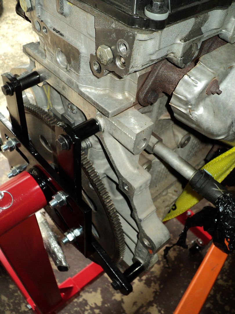
It follows that in spite of how much time, energy, effort and money (not exactly a Total Loss on that score… Stay Tuned…) that continuing to add to the “$85,000.00 GM Atlas 4.2L Engine Repair” long thread would become a Fool's Errand. This change in direction will soon prove out as “True Times Two” because now… with the arrival of this engine; ostensibly being a “Swap-N-Drop” Motor… I will of course be able to have BOTH engines mounted on Engine Stands that will provide 360 Degrees of access in every sense of the word. As it happens, for my situation, Engine Stands are a Godsend that gives the ability to rotate these engines in order to position the areas focused upon with the greatest of ease and convenience, while also being able to maneuver the engines stands on their cast iron roll-around wheels for whatever makes the jobs easier to accomplish, regardless of which one happens to be ready for more work at any given moment.

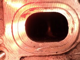
The plan here is to use this new level of relaxed freedom of access to employ some novel reconditioning techniques on the Engine Head and the ordinarily inaccessible combustion chambers and valves in a way that will facilitate renewing all aspects of the upper engine… without the need to remove the head to accomplish this. The link below begins the first of many installments of Photo-Plays that will involve EMS (Each Major Step) as separate sections to follow for the acquisition of and reconditioning necessary to allow what is called by the expression “ A Drop-In Motor”; this popular prejudice being no more than Wishful Thinking that these procedures will always be something that is very easy to do. But truth is this:

Swapping Engines In and Out of ANY vehicle ALWAYS becomes a Long Road… with No Turns in it!

I have included some Flow Charts that can give anyone imagining this job to be an easy one a chance to pause and reflect on all of the required steps to logically take before diving in and finding themselves in the Deep, Dark and Unknown Waters of “How to R&R an Engine...”. The Biggest Problems you can face are Threefold (1) If Your Work Should Fail… You Will Have No Transportation. (2) If Your Work Should Fail… You Will Be Broke. (3) If Your Work Should Fail… You Will Have No Transportation, No Money and You Will Still Have To START ALL OVER AGAIN!

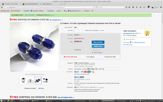
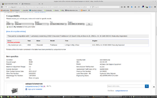
This first series of images will demonstrate that any Jackass can claim to find a Low Mileage, Drop-In Engine in the Price Range of $300-$500… and have damn little proof that this is actually possible… especially where the GM LL8 Engine is concerned… because based upon its Incredible Performance When it Works vs. its Dismal, Difficult and Expensive Repair Cost Reputation when it Doesn't... will clue in both the Seller and the Buyer that you will be more likely to find one that is closer to that “Drops Right In… Runs Good” Dream if you are willing to shell out around $1,000… with an occasional chance to pick up a very nice engine for around $750 to $850.

In the case of this engine… as the object of a carefully planned and LIMITED “Engine Autopsy”… you may discover something dreadful that requires your immediate attention and more expense to fix BEFORE loading up the motor onto a lift and beginning to fall into an even deeper sleep when you experience “The Nightmare of An Engine R & R… Part II”. Then again... As you will soon see… So farI have taken as much hardware off of the engine as necessary to be able to ease my mind so very much about the qualities this motor really has… and that positive outcome really surprises even me. Sometimes… Even a Blind Ol' Hog like me Finds an Acorn in the Woods Once in a Great While!

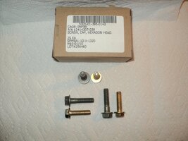
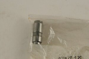
Please note that the images of the (6) 2005 Complete Pistons (Connecting Rods, Pistons, Wrist Pins, Pin Locks and Rings) were NOT pulled out of this engine! Rather… they are a set I picked up for a mere $80.00 on eBay as they looked too good to pass up and their improved design advantages may prove useful when I completely rebuild the 2002 GM Atlas 4.2L Engine presently sitting in partial disassembly inside my son's TrailBlazer. Some of the images I took are of the myriad required GM TTY Fasteners that must obtained,.. one way or another... before the engine is torn down… because they are unique and indispensable for re-assembly. This means (14) GM TTY Bolts for the Crankshaft alone and (12) GM TTY Bolts for the (6) Connecting Rods. But I'm getting a little ahead of myself here.

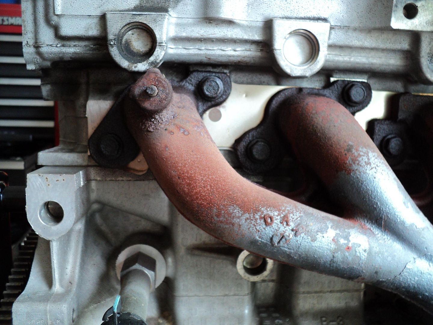
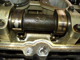
When looking at these photos… try to imagine WHY I followed the partial tear-down and inspection procedures I used in the manner shown…You will need the skills of a Detective to see what must be seen in, on and around your own engine(s) and be certain that before you jump to any conclusions and buy the WRONG MOTOR FOR YOUR UNIQUE SITUATION…. That you read, investigate, study and plan all of your moves and neither wind up with TOO LITTLE ENGINE for your hard-earned money...nor wind up with an Engine that is WAY TOO MUCH in the need to make other modifications in order to get that replacement engine to work properly.

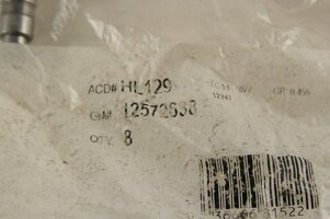
Don't forget that I will be adding additional images of the Parts and Pieces unique to each section, so don't automatically assume that I am missing anything required. Any delays in posting the images will happen because sometimes, the parts cannot be immediately located or have been delayed in arriving. Sometimes patience and return searches on eBay, Google and Amazon will reveal less expensive and more available “Parts Gems” that will be worth waiting for. For example… On average ONE (1) Crankshaft/Cradle Long TTY Bolt will cost around $45.00 A PIECE! I managed to buy these in lots of either Ones or Twos… and in one incident Eight Connecting Rod Bolts became available for a fraction of their GM Dealership value… and yet each and every one came from Authorized GM Dealerships. Some of these GM Specialty Fasteners are used in other platforms with identical part numbers and performance… so you must be clever in seeking out the GM Part Numbers in ALL markets and venues. Sometimes… dealerships fail and sell their inventories to people with way too much money and time on their hands (LLCs) who do not have a clue as to what these items are actually worth and sometimes… they will sell them to you… for a song.

More to Follow…

http://s557.photobucket.com/user/60...RENGINEREPAIR/GMATLASENGINESWAP?sort=2&page=1
 
Last edited:

mrrsm

Original poster
Lifetime VIP Donor
Supporting Donor
Member
Oct 22, 2015
7,737
Tampa Bay Area
This update includes a “Break Down… Of the Tear Down” on this 2004 GM Atlas 4.2L Engine.

http://s557.photobucket.com/user/60...RENGINEREPAIR/GMATLASENGINESWAP?sort=3&page=1

In orders of operation… The work flow shown in the images began with Draining the Engine Oil even though I knew that the oil had been removed as per the EPA Requirements that restrict the transport of mechanical devices that might have contaminated oil inside that will leak out during transport. I wanted to test the theory posited years ago concerning the high failure rate of engines that have not been Power Primed by any of a number of methods due to most of the engine oil either being shaken enough to vibrate the oil steadily downwards via gravity until all of the galleys bleed bone dry… or ... by the same gravitational issue… but related to molecular capillary attraction literally pulling almost every drop of oil steadily “Down the Drain”.

In the case of this engine… there was enough of the residual oil down inside the crankcase to bear witness as proof that this phenomena does indeed occur. The opposite could be seen after removing the Timing Chain-Valve Cover… as the Top End was almost “Pristine Clean” and there was hardly even any residue left during a smear test. Regardless of whether or not this engine qualifies as being a “High Mileage Motor”… The internals of the Valve Train would swear otherwise. I could not find the slightest amount of “Mung”, sludge or Black Oily Dirt you would expect to observe in an engine with 12 Years of Automotive Performance behind it.

While draining the Oil… I deliberately flowed the oil into an opaque, well illuminated container to be able to view the condition of the oil after draining it and make some close observations of the Drain Plug for indications of repeated use. It was the case that the Oil Drain Plug had been removed and re-installed often enough to cause wear and damage and therefore more proof that in the course of its life to date... it has been given an ample number of Oil Changes to sustain it in this good of a condition.

The Engine Oil was tan to light brown… and almost honey coloured, without the slightest hint of any Gasoline odour; a very good marker for determining whether or not the engine has suffered extensive wear to the Pistons and Rings… and likely all of the bearings surfaces as well… but in this case, its absence and the lack of particulate matter suspended in the oil indicates that excessive Blow-By was not present for the life of the engine.

The appearance of the lower crankcase seems to indicate that this engine was nested inside of a Two Wheel Drive Envoy… again...a very good indicator that the SUV was not being used for any Hard Use Off-Road Shenanigans... or towing any Thirty Foot Yachts to worry that six cylinder engine too much. All in All… the present circumstances would suggest that this engine was generally well treated and given regular maintenance that has left it looking very nice inside.

I made a thorough inspection of the Timing Chain, the VVT Exhaust Cam Phaser Timing Gear, the Intake Timing Gear, the Timing Chain Guides as well as inspecting the distance of travel for the Timing Chain tensioner and all of these items were quite snug, without the slightest hint of Chain Play anywhere on the Timing Chain Set and with very ample space for the Timing Chain Tensioner to expand over time. Again… all of these earmarks give a strong indication that the Engine was healthy and just as the Vendor at Heritage Auto Sales mentioned...”A Good Runner”. And so… for the most part I am more than pleased and feel vindicated regarding this purchase expense in lieu of continuing to work on an engine that I KNOW has over 240,000 Miles of Well Cared For...Wear and Tear. I have also been making observations about each removed component and there is simply no fair comparison to be made because this 2004 Motor is in a much better state for continued health and performance than the 2002 Motor.

However… with all of that Sunshine mentioned and greatly welcomed, naturally… there are the Twin Dark Clouds of the Exhaust Manifold bolts (#1 and #6) that snapped off many years ago and then slowly rusted inwards into the Aluminum Engine Head Exhaust Manifold Mounting Bolt Holes and becoming inaccessible by any ordinary means for removal…. (Shades of the $85K Time-Sert debacle) What I cannot understand is this:

IF GM DESIGNED STAINLESS STEEL MLS GASKETS TO GO BETWEEN THE CAST IRON FLANGE POINTS AND THE BOLT HOLES IN THE ALUMINUM HEAD...WHY DID THEY NOT ALSO INCLUDE SMALL MLS STAINLESS STEEL GASKETS TO SLIP UNDER THE HEAD-SPACES OF EACH EXHAUST MANIFOLD BOLT SO THAT THEY TOO COULD “FLOAT AND AND SLIP AND MOVE ABOUT "...WITH THE SAME EASE AND NOT BE SUBJECTED TO THE CONSTANT BENDING THAT THEY EXPERIENCE OVER TENS OF THOUSANDS OF HEATING UP AND COOLING DOWN EXPANSION AND CONTRACTION CYCLES? HELL… I COULD MAKE THEM MYSELF BY JUST BUYING A SECOND EXHAUST MANIFOLD SS MLS GASKET AND SHEARING OFF THE ALL OF THE BOLT HOLE CORNERS TO SLIP UP UNDER ALL OF THE BOLT HEADS!

The only actual revelation from all of this trouble so far… is that with the engine mounted on the stand… it was easy to position the Block horizontally and thereby allowing for the use of an assortment of Drills, Flux Wire Welding of Dorman Exhaust Manifold Down-Pipe Nuts and then trying Easy-Outs, one of which snapped off inside the #6 Cylinder EM Bolt Hole. These failures are forcing me to shift this approach to using Low-Speed, Well-Lubricated Specialty Cobalt Drill Bits and with more time, patience and effort… I intend to “evict” these mechanical equivalents of “Deadbeat Squatters” from being left inside of the head. Unfortunately… This follow on activity will have to wait until I return from The Docs in the morning tomorrow and see whether I will be further delayed should he determine the necessity to operate on my left leg/foot.

I have added today's related images to my Photobucket after finally deciding to take the plunge and select their “$2.99 a Month for 20 Gigs of Storage” which comes to around $30 a year as I had just maxed out today at 3 Gigs of Free Space and I do not want to have to constantly be thinning out the ranks of my prior image uploads. More to Follow...

http://s557.photobucket.com/user/60...RENGINEREPAIR/GMATLASENGINESWAP?sort=3&page=1
 
Last edited:
  • Like
Reactions: Sparky and Mooseman

mrrsm

Original poster
Lifetime VIP Donor
Supporting Donor
Member
Oct 22, 2015
7,737
Tampa Bay Area
http://s557.photobucket.com/user/60...RENGINEREPAIR/GMATLASENGINESWAP?sort=2&page=1

There are several images in the dedicated album on Photobucket that show some close-ups of the Hardened Steel Head Bolt Stamps of the 10.9 hardness M10 x 1.5MM x 50MM Engine Stand Bolts that also have the wide sloped built-in Washer design. These had to be special ordered and will not be part of any stand you purchase from HF. Because this is the first time I have ever had to stand an engine with an ALL ALUMINUM BLOCK... I took great care in locating the thickest bossing areas at the back of the block and tried to space the load as evenly as possible when installing the Engine Stand Arms.

The nightmare of course that is possible here is either using the wrong size and thread depth and stripping out the soft Aluminum thread holes in the back of the block... or using Common Mild Steel Carriage Bolts with washers and then having them simply snap clean off and drop the engine to the concrete deck and cracking the engine block open like a fresh farm egg on the edge of a skillet. I left the motor suspended by the two 6,400 LB Yellow Suspension Straps and after making the minor adjustments needed to balance the arm spacing, I first tightened each of the hardened bolts against the Aluminum Block and then TORQUED THEM DOWN TO 35 FOOT POUNDS before tightening the armature to the back steel support plate with the HF 10.9 M12X1.5MM X 25MM as tight as possible. Whatever else you do with this engine... DO NOT FREELANCE AND HAND TIGHTEN OR OVER-TORQUE THESE 10.9 BLACK BOLTS... BECAUSE THEY WILL VERY EASILY STRIP COMPLETELY OUT!

I later discovered that the short handled HF Factory Rotation Rod was insufficient in the leverage needed to rotate the mounted engine and had to resort to using the White Crank Lever from the HF Cherry Picker. This allowed more control and yet it still took quite a bit of force to get the engine to move. Caution is the byword here...as this process can get hectic enough to tip the whole engine and stand right over... so doing this very slowly with the Stop Pin handy to lodge in the top of outer and inner alignment hole(s) in the stand tube ASAP will be a good idea. In reflection... mounting this engine on the 2,000 LB flavour from HF would have been my first choice... but I have some space and manoeuvring difficulty that makes this 1,000 LB Stand a fair compromise. The 2002 engine will soon be mounted on one of these, too.
 
Last edited:

mrrsm

Original poster
Lifetime VIP Donor
Supporting Donor
Member
Oct 22, 2015
7,737
Tampa Bay Area
http://s557.photobucket.com/user/60...RENGINEREPAIR/GMATLASENGINESWAP?sort=2&page=8

Okay… I lost way too much time today at The Docs to accomplish much today… so the (6) six updated images just show as proof that the ONLY way to properly drill out ANY broken, Grade 8, Hardened Steel Bolts is by using Pure Cobalt Drill Bits … (I got this set today On Sale from HF... and the results were incredible!) To quote the Gangster known as “Brick Top” from the movie “SNATCH” as he is explaining to “Turkish and Tommy” why they should "...Fear any man who keeps a Pig Farm..." :

“They Will Go Through Bone...Like Buttah...” Yup… it was JUST LIKE THAT!

http://www.harborfreight.com/catalogsearch/result?q=cobalt+drill+set
image_24956.jpg

When it comes to drilling out ANYTHING ...from now on… now that I have a Full Set of these from HF...I will use Cobalt Drill Bits exclusively. Please pay particular attention to the condition of how well centered the drill became after I bashed a concavity as close to dead center as I could make it and then “hunted” the initial contact with the drill point until it looked ...Right On Point. Ideally… a Machine Shop would set up the block and use Drill Bits in graduations to remove the hardened steel innards of the broken bolt as close to the seized-in threads as possible and after drilling the bolt out with a bit just exactly as wide as the cut valleys in the thread-line… the remaining threaded portion can be easily withdrawn as all that remains to do after that is to lightly chisel out the topmost exposed thread and after grabbing hold of it with a pair of Needle Nosed Pliers...pull out the remaining portion like a spring “Slinky”.

If you look at the aforementioned six images... you will see that because the Cobalt Bit almost self-centred and also has a “Chip Breaker” that keeps the drill face of 135 Degrees steady and less prone to wobbling around and “losing its guidance”… so to speak. Now even though there remains a little more metal than just the thread line… the fact that the Cobalt Bit stayed true all the way through the process with simple one and two revolutions per cut...while using the foaming, sticky lubricious CRC Aerosol Cutting Oil (Uhh… The only thing that “comes” to mind to describe how it feels is… well… just think “Pearl Necklace” here... and that will clue you in as to how well this stuff lubricates). Yet… the stuff also hangs onto all the mini-chips that need to be constantly scooped out of the drill hole using repeated sprays followed by the application of many fresh Q-Tips as "Chip Grabbers":

http://www.harborfreight.com/12-oz-thread-cutting-lubricant-92581.html

image_13642.jpg


If you look closely at the spidery web-like lines in and around that bolt hole... what you are seeing there are NOT artefacts of metal damage to the Aluminum head... but rather the gossamer-like cotton threads that got pulled out while twisting the Q-Tips in and out of the bolt hole in order to prevent the Cobalt Bit from scooping up its own chip refuse and grinding them into the bolts threads in the head doing "Bad Damage". This might seem like a distraction… but the fact is these Cobalt Bits are incredibly fast cutting and you have to keep slowing yourself down and NOT drill into the Aluminum Head too damned far!

Once again… I was on my feet way too long late into this afternoon… and so the final job of removing the remaining portions of what is left of the Exhaust Manifold Bolt will have to wait until tomorrow morning. It follows that after that… I will tackle the one on the opposite side of the head with the Easy Out that snapped off inside of the bolt hole yesterday. This will make for a sincere challenge of “Cobalt vs. Carbide”… and after a very long day of doing that, we'll know who the winner is...

More to Follow...

http://s557.photobucket.com/user/60...RENGINEREPAIR/GMATLASENGINESWAP?sort=2&page=8
 
Last edited:

mrrsm

Original poster
Lifetime VIP Donor
Supporting Donor
Member
Oct 22, 2015
7,737
Tampa Bay Area
http://s557.photobucket.com/user/60...RENGINEREPAIR/GMATLASENGINESWAP?sort=3&page=1

Okay… Today was a mixed bag of successes… with the usual “Heisenberg” thrown in at the end for Good Measure. I took an inventory of all my various specialty drill sets and conducted one final search on Youtube for anything that seemed worthwhile to know... and spot-on to answer the following question:

Will Cobalt Drills work against any Carbide Steel Materials?” The Short Answer is ...“No.”

After taking the time to watch this very interesting Trial and Error Video listed below as a treatise on what Twist Drills are either capable or incapable of drilling into and through, I came to the conclusion that in this case, the only way to get the 5/8” long snapped off Carbide Steel “Easy Out”...OUT… was to use:

MORE CARBIDE” (Yeah... I know... Rhymes as an assonance with "More Cowbell")

The only problem that developed was that I eventually had to settle with using about a half-dozen “Wandering Carbide-Tipped Masonry Drill Bits” along with frequent rest periods due to exceeding the Duty Cycle of my Electric Drill so many times during the long day that it actually took in order to finally get enough of the damn thing removed...by literally “micro-chipping” away at the damned thing until I could fish out the shattered pieces of the Easy-Out and continue drilling out the Grade 8 Exhaust Manifold Bolt. Unfortunately… I was so focused on making downward progress that I missed the gradual shift and the “Wandering Nose”of the drill bit off to one side of the bolt and into adjacent meat of the Aluminum Engine Head.

So now the only way out of this Hell without having to just pull this head and put the Brand New One I still have available onto this engine… is to either resort to using a Helicoil Repair Kit… or instead, since I still have the Time-Sert Tool Kit along with a Dozen Inserts left over from the prior successful FUBARed Head Bolt Hole Repair I completed without incident on the “85K GM Engine Repair”, I can see no good reason not to repeat this procedure on an Aluminum Head… especially since the Head Bolt Sized replacement Exhaust Manifold bolt goes through all of the holes in the Old Exhaust Manifold with room to spare!

Now you might remember and wonder about the difficulty I would ordinarily be facing if the engine were in its normal upright position forcing the need to do all of the work with the engine in the SUV and sitting at a Right Angle to all the efforts to do properly aligned drill-outs and re-threading. But since this engine will be in the solid horizontal position while mounted on the Engine Repair Stand, just as the surface of the $85K Engine Block was when I used the Time-Sert Kit the first time, this repair should not be any different… and actually much easier to access.

What I WILL have to “McGyver” this time though, will be slicing out the mid-section of the Old Exhaust Manifold that has the Three Off-Center Bolt Hole Flanges using the 7” Angle Grinder and then drill out the one hole that lines up over the messed up Bolt Hole location as it will need to be widened enough to allow the insertion of the Time-Sert Hardened Steel Drill and Tap Guide. Once the Centering Alignment Pin is inserted through the guide and properly in place… I can tighten down the other two Modified Exhaust Manifold Flange Holes with Stock Grade 8 Bolts and solidly fix everything in place. After that… I'll just use the same procedures to properly Drill Out, Tap and Re-Thread the Aluminum Head and then install the Time-Sert Insert (See 85K Thread) with the included Very High Temperature Thread Locker and secure it with the Lock-Down Tool… DONE!

Everything You Need to Know About Drill Bits! (Good Info... But the VOP is CARELESS!)

Time-Sert...
https://duckduckgo.com/?q=youtube+time+sert&t=ha&ia=videos&iai=qFSyfY1VLtU

EDIT:

Some of the remaining hardware "Stragglers' that will make up the various "Necessary Sets" (Try saying THAT 10 Xs in a Row) of Fasteners have arrived this evening and I grabbed a handful of images of those that are now Complete, Bagged, Tagged and Boxed to sit in expectation of a time when the 2002 4.2L Engine will be extracted from the TB and mounted on an Engine Stand for the complete rebuild. I also ordered a pair of Metric Male and Female Thread Chaser Sets which become absolutely indispensable for cleaning up Bolts and Bolt Holes that ordinarily might not get the attention they deserve and cause other problems when some of the external components do not attach onto the engine just quite right.

For example... Certain Hornets of the Mud-Dauber species will pack thick, durable mud and dirt into various locations on engines that have been sitting for extended periods of time on Stock Shelves and out on the grounds of the various locations of Salvage Yards around the country. These insects will create the problem of causing bolts and other fasteners to either seat improperly or not al all. Using these Thread Chasers can help when the block is being inspected prior to complete disassembly and clean out these "hiding places" before beginning the re-build.

DSC06574.jpg DSC06577.jpg DSC06579.jpg DSC06581.jpg DSC06582.jpg DSC06584.jpg
DSC06579.jpg
 
Last edited:
  • Like
Reactions: Mooseman

mrrsm

Original poster
Lifetime VIP Donor
Supporting Donor
Member
Oct 22, 2015
7,737
Tampa Bay Area
Occam's Razor

(Non sunt multiplicanda entia sine necessitate)

"Entities must not be multiplied beyond necessity"

This attribution stems from the 14th Century philosophical notion that “The Simplest Means of explaining ANY Problem is Almost Always… Correct...”. I delved into a Real World approach using this very idea this morning, but I had a sketchy beginning. I was using my 7” Cut-Off Tool to remove just the Cast Iron Exhaust Manifold flanges from the outer edges and where the three exhaust ports meet in the middle to use as a Basic Sturdy Template that could be drilled out to support the Time-Sert Guide just like its OEM “Four Square Drill Guide Plate” that was used in the $85K repair of the FUBARed Aluminum Engine Block Head Fastener Repair.

This was an involved affair of having to set up a pair of saw horses and a 2” X 4” supported Plywood Table Top, with all the requisite Tools and Clamps, Eye and Ear Protection, etc., with the idea of using the Old Engine Head to practice on and see what happens when drilling out a Bolt Hole that will be modified to accept a Larger Bolt. However… I remembered that in spite of this expensive tool-kit with a very thick, Black Anodized Aluminum Plate that usually gets bolted on top of the Engine Block to make all the necessary and precise Tool Alignments... behave themselves would never fit into the restricted confines of the Head and Engine Block in this application. Almost as soon as I finished that last Cast Iron cut, I realized that I was working on the problem from the wrong direction. As fun as it can be to do such things… a steady diet of having to sort through a raft of Bad Ideas to figure which one will be Best will be enough to give anyone a Belly-Ache. And besides… Occam's Razor was about to get into the mix.

I opened the heavy vacuum formed lid to look over the complete set of Time-Sert tools to find an alternative in there… and then I remembered that it was a $30 eBay purchase of a super hard plastic support plate designed specifically for the GM Atlas 4.2L Engine. So all I really needed to do was to get a few “spacing measurements” and then just cut off as much or as little of the Drill Tool Plate as needed and figure out a way to bolt the plate down one end of the closest adjacent Exhaust Manifold Head Port and secure the alignment hole perfectly centered over the offending Bolt Hole containing the broken-off Carbide Easy-Out remnants and then apply all manner and combination of High Speed Steel,Cobalt and Carbide Drill Bits and simply keep up a steady cycle of Drilling Small Amounts… Removing the Drill and Guides to Evacuate the Bolt Hole with Canned Air and determine its progress and then Re-Lubricate all the parts involved go back to Drilling As Often as Necessary to get the 11MM Wide Hole Prepping down to the depth required to Tap and Install the Time-Sert Insert.

Because of the Incredible Hardness of the Broken Carbide Easy-Out... It took almost 10 Hours of work today in order to finally get the Errant Bolt Hole ready for this last portion…. And that will happen tomorrow after I get a Good Night's Sleep. The photos tell the story… (Using the “McGyver Rolled Up Strip of the Side of an Aluminum Cat Food Can” was a necessary evil when trying to center the Cobalt Bit in the larger Drill Guide for the “last little bit” of drilling needed to get the job done.) By the way... All of this work was actually done of the "Swap-N-Drop" Engine...and NOT as a test first on the Old Engine Head.

http://s557.photobucket.com/user/60...RENGINEREPAIR/GMATLASENGINESWAP?sort=3&page=1

Oh... The Last of the 14 Crankshaft/Cradle Bolts finally wandered in and so the Second Set of the Necessary TTY Bolts got Bagged, Tagged and Boxed to sit on the expectation of the rebuild of the 2002 GM 4.2L Engine.

More to Follow...

DSC06585.jpg DSC06586.jpg DSC06587.jpg DSC06588.jpg DSC06590.jpg DSC06589.jpg DSC06591.jpg DSC06592.jpg DSC06593.jpg DSC06594.jpg DSC06595.jpg DSC06597.jpg DSC06596.jpg DSC06598.jpg DSC06600.jpg DSC06602.jpg DSC06603.jpg DSC06604.jpg DSC06608.jpg DSC06606.jpg
 
Last edited:

mrrsm

Original poster
Lifetime VIP Donor
Supporting Donor
Member
Oct 22, 2015
7,737
Tampa Bay Area
Okay... Just catching up in this post on the continued progress with getting the Time-Sert installation closer to completion. After I managed to drill deep enough in order to extract the final mess of carbide tool steel chunks and the remnants of the Grade 8 Broken Bolt... I realized that the Cobalt Drill Bit had penetrated into the Water Jacket, albeit, obviously empty at this moment but a circumstance that would need to be addressed by simply cutting the M11X2.0 Threads a little deeper down the Bolt Hole and ultimately fixing it permanently by making up a thin plug of Aluminum and then afterwards, squeezing in some J B-Weld into the small hole... and then pushing the Metal Plug almost all the way down inside the hole into the JBW Goop and then let the repair harden overnight before continuing to install the Time-Sert Insert down on top of this permanent, leak-proof "fix".

The problem I was facing today was realizing that while all of this expensive Time-Sert equipment is really neat for solving problems like this... unfortunately, the kits are almost exclusively designed for repairing HEAD BOLTS and there are no additional shorter length GM Tools or Inserts. Consequently, the Cutting and Counter-Sink Drill Bit and the M11X2.0 similar sized Tap are simply way too long to be able to work beyond the point of the initial hole preparation... and impossible to use to go deep enough with the drill bit to cut in the ridge chamfer around the top of the hole to allow the Time-Sert Insert a flush ledge to wedge against and sit upon so the last tool can solidly lock the Insert in place in the final tightening sequence.

So I put on my Thinking Cap and came up with the idea of using the wood handle from one of my Bill Alexander Magic of Oil Painting brushes and use it like a centered dowel down inside the Bolt Hole and a 9/16" Wood Hole Drill Bit with the starter point inserted into the dowel and allow the outer edge of the cutting tool to slowly cut into the soft Aluminum head surface deep enough to properly seat and hold the Insert in place for the final locking and tightening sequence.

The other issue involves the excessive length of the M11X2.0 Thread Cutting Tap that has such a long lead-in that it bottoms out inside the Bolt Hole before all of the threads needed are completely cut. What is called for here is an M11X2.0 Bottom Tap...but trying to find one of those is like searching a barnyard for Hens Teeth. I finally found "A Tap" which I will probably need to modify by grinding the damned thing down enough to have a square face that can be threaded into the existing threads and work the tool downwards until a sufficient number of threads have been cut. Nonetheless... I am pleased with the steady progress I made today and the attached images will show how that was done... but keep in mind that the threads you see cut into the face of the engine head are for the Time-Sert soon to be installed... and NOT for the threading in of any bolts... just yet: (Performing ANY of this work while the engine is still inside the SUV would have been absolutely IMPOSSIBLE!) More to Follow...

DSC06613.jpg DSC06619.jpg DSC06615.jpg DSC06614.jpg DSC06618.jpg DSC06617.jpg m11x1point5.jpg handtapgen__29626.1407859393.1280.1280.jpg DSC06609.jpg DSC06612.jpg
 
Last edited:
  • Like
Reactions: Mooseman

mrrsm

Original poster
Lifetime VIP Donor
Supporting Donor
Member
Oct 22, 2015
7,737
Tampa Bay Area
I mentioned early on that I would employ some novel “Engine Head Reconditioning Techniques” being done while the Head and Engine are still “fasten”-ated with each other and which can only be attempted while the engine is mounted onto a Rotational Engine Stand. The uncommon opportunity we face here though is that in addition to the aforesaid “Engine on the Stand” … we also have a free standing, identical Engine Head to pair up with while doing this experimental chemistry that can be more easily manipulated and viewed with stunning clarity on top of a work table sitting out in my driveway in the Florida Sunshine.

But as with all scientific experimentation, a “Good Scientist” (or… even an “Evil” one, for that matter...) Must Only investigate One Variable At A Time. And just as important, knowing as much about the chemistry experimentation that others have done before… with accurate and reliable tabulated results... will save you a lot of time and unnecessary effort in trying to either prove or disprove the work that so many others have done so much better all ready. To that end… here is what must be called “The Definitive Breakdown of what Seals will Survive or Fail When Exposed to Chemical(s) X”... or when spoken in Plain English:

“Everything You Ever Wanted to Know About Seals... But Were Afraid to Ask.”:

http://www.mossrubber.com/pdfs/Chem_Res.pdf

About seven years ago… I decided to design and build a completely Off The Vehicle Electronic Fuel Injection Cleaning Machine that could be assembled by anyone with access to the Internet and a Salvage Yard and an occasional trip to Autozone for the Cleaning Liquids to be used. Its ironic that well featured here is the Fuel Rail and EFIs that came off of a 2000+ GM Atlas I6 Engine that also features an intimate breakdown of what our EFIs look like from Top to Bottom… Inside and Out. This is the link to all the Videos and Images I used to document four generations of these experimentations that you might find useful:

http://s557.photobucket.com/user/60dgrzbelow0/library/HOMEMADEEFICLEANER?sort=3&page=1

The reason I mention all this now... is because way back then, I had to seriously consider using some chemicals that would not only effectively clean out all of the Mung, Dirt, Detritus and Debris that pumping 10,000 gallons of Sh*tty Gasoline through tiny micron-sized screens can build up over the life of any engine… and also possibly ATTACK AND DISSOLVE THEIR SEALS and then leak out all over my ostensibly clever machinery and ruin everything. What I discovered was that in general… GM and others in the automotive industry had faired quite well on a steady diet of all manner of seals made out of either Dupont Teflon (PTFE) in either “The Brown” flavor… or Viton in the “The Blue” flavor.

But even as comprehensive and careful as I was about doing all of this with chemicals like “Lucas Oil” and “Chevron Techron” Gasoline Treatment in mixtures that many Chemists would have suggested, “Okay Bobby… Put DOWN the Bottles...and Back Away VERY SLOOOWLY...” I never actually tried to use GM Top Engine Cleaner (AKA “Canadian KLEENZ” in the GWN). And so… Since “Past is Prologue” in this story… before I subject the “Swap-n-Drop” Replacement Engine to a sustained bathing in various positions and under some unique conditions with lots and lots of this stuff… I want to make damned certain that the PTFE Valve Guide Seals and the PTFE Engine Seals located on both ends of the Crankshaft will not dissolve before my very eyes. And so… #1 on the Test Runway… will be the Old 2002 GM Atlas Free Standing Engine Head ...and if those experiments work out and do NOT ruin the seals… then we'll try it out on the “Swap-n-Drop” Motor. Here are some images I copped of these Viton Blue or Dupont Brown “Poly-Tetra-Flouro-Ethelyne” Seals from my Photobucket:

MOCKUPANDBUILDOFNEWFUELRAILDESIGN01.jpg
NEWFUELRAILFINALBUILD25.jpg MULTECEFIFILTERKIT-1.jpg
 
Last edited:

mrrsm

Original poster
Lifetime VIP Donor
Supporting Donor
Member
Oct 22, 2015
7,737
Tampa Bay Area
This additional post is meant to inject some caution and understanding into the earlier topic of fasteners and mention the underlying aspects of the GM Atlas 4.2L Engine that will divide itself from the ordinary mechanical repairs and endeavors most mechanics experience and separate the Weak vs. The Strong among us:

TTY FASTENERS

This engine is more akin to being an "Aluminum Balloon" that swells up when it is warm and working and then shrinks its volume just as dramatically as it cools down and comes to rest. The binding of the myriad parts, both static and dynamic demand Fasteners capable of "Stretching with the Swelling" … without snapping off the various bolts that tie things together... and so it behaves very much like a Rubber-Band; contracting and expanding while the bolts stretch tight enough to keep things in place over many thousands of such oppositions in temperature and temperament.

It is facile to imagine that the solution to broken bolts in this motor would simply be to use thicker, stiffer bolts… but if we did...worse things would happen if such theoretically "more robust" hardware was employed. All manner of havoc would occur from cracked cylinders to total failure of the containment of the Rotating Assembly… as they could come apart at elevated RPM and self-destruct as a result. The TTY fasteners being used in Modern GM Engines are what allow these engine to “Balloon Up” in their overall dimensions and then “Shrink Down” when all manner of heating is asymmetrically induced involving all kinds of dissimilar metals...often situated by proximity almost on top of each other and time and time again… be able to negotiate a peaceful and tightly bound co-existence.

The problem comes however when these engines are being disassembled and the tightening tolerances that were once applied during their manufacture are so very close to their Estimated Failure Points… that no matter how careful you are with your “unwinding tactics”; even when applying the torque in reverse needed to break these bolts loose very, very slowly… you will inevitably wind up breaking a few… or in some cases, almost of them... by snapping off these fasteners at their weakened “Stretch Points”. This creates the necessity of your having to take on extra, often seemingly extravagant actions in order to extract the remaining snapped off bolt shanks. It is during that secondary layer of additional steps standing in the way of what will actually look to you like an absurd expression: “R&R”… Remove and Replace… because what follows on from this dreadful mechanical apparition will force you to learn and do things that even experienced mechanics dread doing: Applying Power Tools to Drill Into and Grind Upon an Aluminum Engine Block.

I consider myself a Pretty Good Mechanic… if only because I have lived so much longer than most of you and have simply had more time to break and damage mechanical things; arguably developing the wisdom and experience necessary so as not to repeat my mistakes. But even with that fat layer of experience… In all of my days, I have never had one, single occasion to work on an All Aluminum Engine… Until the Wondrous Workings of the GM Atlas 4.2L Engine Failure. And if you want to find out how bad things can get in very short order when working on this Novel Motor without a deeper level of understanding… just read the “85K GM Atlas Engine Repair” Post at the link below… but skip everything there in Black Ink and just dial in on the RED TEXT. If you do this, you will come to realize that even if it turns out that you break every single head bolt when taking this engine head off of the block… removing the broken bolt shanks from this engine while the head is still in place... could ultimately Destroy the Engine Block!

http://gmtnation.com/forums/threads/the-85-000-00-gm-4-2l-engine-repair.14423/

This next observation would almost be funny… were not that the problem it solves for GM by making it almost impossible to use any other fasteners than the ones their engineers specifically designed for their TTY Head Bolts also makes it impossible to find any other lengths for Bolts having this same, Weird Metric Flavor of M11 X 2.00 for their Bolt Thread & Pitch Count. I dare you to perform a Google Search and locate any of these in say M11 X 2.00 X 25: Because I have already searched endlessly ...and I can't ...and I really only need JUST ONE!

What I will probably wind up doing is taking a Brand New M11 X 2.00 Head Bolt and cutting it off around the mid-shank area and then just use the Machine Die shown below and cut in threads for the more common M10 X 1.50 Nut measurement. I'll use THAT Bolt as a Stud in the Upper, Outer #6 Exhaust Manifold location that I will be finishing up shortly with a Time-Sert Repair…. And then Tighten it down with a Metric Class-8.8- M10 X 1.50 Nut!


M10 X 1.5 Carbon Steel Hex Die
90dwtbswhex__23081.1407854185.1280.1280.jpg


https://drillsandcutters.com/m11-x-1-5-carbon-steel-hex-die/

If I do the measurements correctly and pre-fit everything on the bench, when the New Exhaust Manifold is ready for installation, I will do a dry-fit with the engine on the stand and make certain that each and every fastener has ample clearance… even if I have to do a little “persuasion” by drilling out certain holes in the Cast Iron Manifold to get everything lined up just right. Once again… since I can have the engine laying on its side with the Exhaust Manifold side of the Engine Head facing up… mocking everything up without having to fight with gravity and the tight spaces that would be a serious impediment if the engine were inside the TB… should be a much easier task to work on.

This is a College Level Engineering Handout on Mechanical Fasteners with numerous Listings and Tables that have an enormous amount of Good Information that might just come in very handy some day!

http://homepages.cae.wisc.edu/~me231/online_notes/dimensoning/fastener_handout.pdf

While I agree with the following idea of having the bolt holes “Thread Chased”... I disagree that these bolts should go in “Bone Dry”, as I believe that the metal galling and “Bolt Snapping” that can inevitably happen between Aluminum Threaded Bolt Holes and Steel Fasteners will increase rather than decrease without the use of some very, very light lubrication. The rest of the data herein has value: (Did they really mention using "A BF Hammer"...? LOL)

http://www.engineprofessional.com/TB/TB021615-1.pdf
 
Last edited:

mrrsm

Original poster
Lifetime VIP Donor
Supporting Donor
Member
Oct 22, 2015
7,737
Tampa Bay Area
This is One...
That Just Got Done...
Like a "Bolt" out of The Blue:

When watching the video...ignore all the lead-in information about the Lincoln Welder… the real purpose of the OP's video is to show you “How to use a Machine Tool Die to Cut Threads on Round Stock Steel”. I used this identical technique to cut new M10X1.5MM Threads that are a “DBOM” (Dead Balls On Match) for the use of the nut hardware from the Dorman Three Bolt/Nut Exhaust Flange Triplets used to attach the CAT triangular flange to the lower portion of the GM 4.2L Exhaust Manifold. I figure that since the hardware has already proven itself on this identical application… using just one nut from this kit after taking an old GM 4.2L TTY Head Bolt and cutting some new threads for the nut should make all the prior repair work of the Time-Sert completely satisfactory in holding down the top outer flange of the #6 Exhaust Port to the OEM GM Exhaust Manifold better than new.

It is very important to draw some distinctions between the Round, Mild Steel Stock being threaded in this video...and the Grade 8 Bolt that I have modified in this instance. There was absolutely nothing that was easy about doing this. The steel shank involved here fought me every step of the way...even causing me to break my vise towards the end due to the amount of tightening required to keep the Threaded Bolt portion from spinning loose while wrapped in Copper Sheets as I worked the Die/Handles down ... literally One Thread Line at a Time!

This work cannot be done right with Cheap Tools! I like buying my tools from Harbour-Freight as much the next Man... But in Special Circumstances like this one... You Can't Risk ANY Tool Failure at ANY Point During the Work.. And so Only The Best that Money Can Buy will Make the Grade for this Job.


Here is what is required to accomplish this Metric-Mech-Mod:

(1) Irwin (Hanson) 12 Piece Self-Aligning Tap and Die Set (The Basic Kit comes with SAE HW)
(2) Irwin (Hanson) # 1897562 Metric Dies: M6-1, M8-1, M8-1.25, M10-1.25, M10-1.50, M10-1.5, M12-1.25
(3) 2-3 Used GM Atlas 4.2L Cap-Screws (Head Bolts) for practice& Final Finished Dual Thread Stud
(4) Cutting Oil
(5) Small Squares of Plywood to sandwich the Old Bolts in between, Then Aluminum pieces...and finally I had to resort to COPPER Wafers from a CPU Cooler because the other things would NOT Grip and Hold the Bolt!
(6) A 7” HF Cut-Off Tool to slice the Cap-Screw Heads off of the Bolt Shanks
(7) Bench Vise (..AND 22” LAWNMOWER BLADE… See the Images...You'll Understand Why...)

This is the procedure to be followed (with more frequent “Chip Cleanouts” and use of more of the Lube:


And HERE are the images that show how things worked out… even after a few things got “Screwed Up” here and there:

DSC06667.jpg DSC06657.jpg DSC06663.jpg DSC06659.jpg DSC06656.jpg DSC06655.jpg DSC06654.jpg DSC06653.jpg DSC06650.jpg DSC06652.jpg DSC06651.jpg DSC06649.jpg DSC06648.jpg DSC06647.jpg DSC06646.jpg DSC06645.jpg DSC06644.jpg DSC06643.jpg DSC06642.jpg DSC06641.jpg DSC06640.jpg DSC06623.jpg DSC06622.jpg DSC06620.jpg
 
Last edited:

mrrsm

Original poster
Lifetime VIP Donor
Supporting Donor
Member
Oct 22, 2015
7,737
Tampa Bay Area
Just an added look at what the New Modified Exhaust Manifold Hardware looks like when threaded up inside the Time-Sert Insert. As soon as the M11 X 2.00 Bottom Tap arrives and I can cut the remaining threads into the head as far down as is reasonable to attempt, the next thing to do will be to mix up the White and Black JB-Weld Components in equal measure to very solid Gray colour and then use an Aluminum Plug with tiny drill-outs for the stuff to ooze into for a better and more secure fusion. But first, I'll need to clean out the Bolt Hole with some Acetone and then stuff some of the JB-Weld into the small the opening in the water jacket at the very bottom of the hole. Afterwards, I'll force the thin Aluminum Plug in all the way into the bottom. Leaving this arrangement to cure overnight before attempting to install the Time-Sert Insert seems like a prudent precaution to take... and so I shall:

More to Follow...DSC06669.jpg DSC06670.jpg DSC06671.jpg DSC06674.jpg DSC06673.jpg DSC06672.jpg
 

mrrsm

Original poster
Lifetime VIP Donor
Supporting Donor
Member
Oct 22, 2015
7,737
Tampa Bay Area
I cannot understand why it is that you can order ten thousand parts and pieces that you don't immediately need and almost as soon as you press the "ENTER" key... there will be a loud knock at the door like the one in The Matrix (1) "Knock Knock... Neo...". But if you've ordered One Special Tool that you need to have ASAP... it seems like it takes forever to arrive. Such is the case with that damned M11X2.00 Bottoming Tap.

Oh Well... In the meantime, I thought I should re-visit something we were all very surprised to discover that worked well beyond any expectations when it came time to de-carbonize the top of the open engine on the $85K Engine Repair using the GM Top Engine Cleaner. But to be fair to the genius of @Mooseman's original suggestion to use that GM product... and for the sake of economics if nothing else, I thought I would investigate the possibility of finding something as comparable in performance... but less "Pricey" than the almost $14.00 per can that this stuff costs. Even though the can contains 13 Ounces of this powerful cleaner... every time any "cleaning" of any part of any engine is involved...it always takes at least Two Cans of whatever the recommended amount is... (if not more in some cases...) and so I try for over-kill if I can get such preparations at a better price.

And sure enough... as it happens, there are actually (3) Three Players on this De-Carbonizing Field as listed below... and the lowest price of all is won here by the MOPAR product; which after reading all of the reviews is very comparable to the GM product...and costs around $3.00 less per can! As for the CRC stuff... I have not tried it out yet... but I would love to get my hands on a few of their Extra Long Red Plastic Spray Nozzle Tubes to use in the future on other tests when the engine is back to running again.

One of the other things I discovered was that by using the GM Top Engine Cleaner in concert with White Lint-Free Microfibre 12" X 12" Cloths was that not only does it hold the GM Spray Foam in better and closer contact with the metal surfaces of the engine that have been "covered in sticky carbon" and remain perpetually "damp" with the stuff... but as the carbon black goo is broken down and emulsified... it tended to soak deep inside of the Pure White cloths; absorbing and hanging onto the carbon residue... especially on the Piston Tops. What I am proposing to do is to use the MOPAR TEC (Also comes out as a FOAM like with the GM Product) and stuff these White Microfibre Cloths inside the Exhaust Ports of the Old Test Engine Head and see how the dissolving process progresses.

I mentioned my concerns already about doing damage to the PTFE seals inside the Donor Engine if the GM or MOPAR TEC proved to be too strong of a solvent...and so I am going to take a sample of both "The Brown" PTFE and "The Blue" Viton EFI "O" Rings and submerge them in some small containers for a few days and determine whether or not using this stuff in such great concentrations and quantities as I want to will actually risk damaging the Valve Guide Seals or the Front and Rear Crankshaft Engine Seals ...essentially made out of these identical materials. Here is a very informative article on Valve Guide Seals and the implications for what can make your engines run poorly if they do not "seal" properly:

http://www.enginebuildermag.com/1998/07/valve-stem-seals-materials-and-designs/

Here is a listing of the "Big Three" in the De-Carbonizing Chemicals Arena and the Best Deal on the White Microfibre Towels:

https://www.amazon.com/dp/B000QII698/?tag=gmtnation-20

upload_2016-7-22_10-36-55.png

https://www.amazon.com/dp/B00BV4D97K/?tag=gmtnation-20
upload_2016-7-22_10-37-26.png


http://crcindustries.com/auto/?s=05312

https://www.amazon.com/CRC-Engine-Cleaner%2c-Aerosol-5312/dp/B00AJVFEOW/ref=sr_1_2?ie=UTF8&qid=1469193892&sr=8-2&keywords=CRC+TOP+ENGINE+CLEANER

upload_2016-7-22_10-37-53.png

https://www.amazon.com/dp/B00QGCXPRG/?tag=gmtnation-20upload_2016-7-22_10-39-3.png

--^^--- "Follow the White Rabbit ..." LOL
 
Last edited:

mrrsm

Original poster
Lifetime VIP Donor
Supporting Donor
Member
Oct 22, 2015
7,737
Tampa Bay Area
Finally today... I had the late chance to stand up, post-meds topical application, for a long enough time frame to work on the other Broken Bolt Shank located at the #1 Cylinder Exhaust Port. I had complete success using the "Other Half" of the Irwin-Hanson Tap and Die Tool Kit along with an SAE Easy-Out - made by The OEM Company in removing what was left of the damned thing after drilling it out very close to the margins of the Aluminum Bolt Hole threads. I would not want to have gotten much closer than what you can see in the attached images.

When viewing these images... please take note of the Black Rust Grooves that remain on and into the surface of the #1 Exhaust Port in the head. As you can clearly see... the Cast Iron of the Exhaust Manifold Flange over the #1 Cylinder EM Port must have swung widely under the influence of the normal motions the engine experiences during periods of acceleration and deceleration and more than likely under a similar influence of changes in temperature as well. Without being held fast... those grooves were worn into the soft Aluminum areas.

If you view the "Pre-Disassembly" images (Page 9 at the link below)...you will clearly see the Rusty Heads of the Broken Bolts in the #1 and #6 Cylinders REMAINED IN PLACE AFTER SNAPPING OFF: HOWEVER... IT DOES LEAVE A VISIBLE CLUE THAT THE BOLT IS BROKEN BECAUSE IT WILL LEAVE A RUSTY PATINA ALL AROUND ON THE STAINLESS STEEL MLS GASKET....!

DSC06402.jpg

DSC06342.jpg

http://s557.photobucket.com/user/60...RENGINEREPAIR/GMATLASENGINESWAP?sort=3&page=9

...so if you decide to skip removing the Exhaust Manifold while thinking, "Well... all the Bolts are In Place...Why Bother?" Having to do this repair once the engine is tucked under the hood will make you rue the day you decided to "Just...Skip It!"

At one one point in the Movie "Prometheus... The Android "David" is fiddling around with the Deadly Contents of the Alien Ceramic Pod... when he gloobers a bit of the disgusting Xenomorphic Junk on the tip of his index finger ... and while holding it up to the light to get a closer look at it, he proclaims:

"Big Things... Have Small Beginnings..."

The same can easily be said of "little problems" concerning this GM Atlas Engine that can quickly devolve into serious ones. In this instance... the forces that have been acting upon the Small Fasteners that theoretically are supposed to hold the Exhaust Manifold "Fast" in place... in particular at its most extreme locations on the block (#1 and #6 Exhaust Ports) cannot possibly resist the repetitive bending and twisting forces being imparted by the natural motion of the engine while riding the three "shakeable" points to move at the the two Engine Motor Mounts and the Transmission Mount. Actually... there is a Fourth Mount... if you consider the one that the Catalytic Converter Long Bracket Pin rides inside of in its Rubber Mount as well. Everything Mechanical that is in between those Four Points are Extremely Dynamic... Much too much so for the Sh*tty design and method for securing the Exhaust Manifold to the GM Atlas Engine Head.

Therefore... if you are going to take the time and trouble, as has been the necessity here, of Removing Broken EM Bolts... then by all means... Invest in also replacing ALL of these mounts BEFORE INSTALLING THIS "SWAP-N-DROP" ENGINE. If nothing else... perhaps doing so will minimize the problem and maximize the time between the R&R and the NEXT time doing this will be necessary. I have hand-diagrammed some measurements for you... that while being in the realm of "Small Beginnings" will have "Big Consequences" when these Fasteners begin to fail!


DSC06686.jpg DSC06685.jpg

EDIT: THIS WAS A VERY IMPORTANT FINDING...!
I neglected to mention that when using the Irwin-Hanson Tap Holding Tool for the #1 EM Broken Bolt Extraction with the #3 OEM Easy-Out... that I took a dramatically different approach to "levering" the tool by taking advantage of its Large Hex Nut top portion. In order to REALLY sense and feel what the tool was doing and NOT have to fight with it by using an enormous amount of "local muscle" that might cause THIS Easy-Out to break just at the other did... I pulled the long centre-pin/handle out of the side of the Tool Head and applied a 26MM Socket to the top of it and then attached a VERY long 1/2" Breaker Bar. Now this might seem counter-intuitive for the goal of NOT using Too Much Torque.... but actually doing it this way gave me an Enormous Mechanical Advantage.

At the extreme length of the handle... very slight pressure...with extremely small inputs allowed for the centre of the axis of rotation felt in the middle of the Easy-Out to turn at even smaller rotational increments... and the results were absolutely magnificent! As I applied and then relaxed this very slight pressure... I had a perfect means of "feeling" the exact moment that the Broken Bolt remnant "Broke Loose". I felt an overwhelming sense of relief when this happened and as you can see from the second close-up of the interior of the Broken Bolt... that the Easy-Out had ever so gradually "bitten" into the inner drill-out hole the bolt and grabbed so well on the first few motions that it yielded with "ease" as the tool name implies that it should have.
DSC06691.jpg DSC06694.jpg DSC06700.jpg DSC06698.jpg DSC06682.jpg DSC06681.jpg DSC06678.jpg
 
Last edited:
  • Love
Reactions: 808

mrrsm

Original poster
Lifetime VIP Donor
Supporting Donor
Member
Oct 22, 2015
7,737
Tampa Bay Area
This covers the idea that sometimes... a "One and Done Tool" will have to be taken off the shelf, dusted off and used to solve an alternative problem...and then finding this much variety for the kit in both Metric and SAE is real big surprise!

http://www.timesert.com/html/approved-GM.pdf

When you are faced with a mechanical issue that has only one or two possible solutions... they always seem to come with a heavy price tag as well. It can often be argued that an alternative solution can be discovered... but sometimes... you have to just Bite the Bullet... and Pay the Piper... or just plain Hand Over Your Wallet during this Robbery in order to save the day.

When I made the mistake (This was almost a "Pay-Per-View Face Plant FU" on my part) of skip-drilling sideways into the top front bolt areas of the #1 Cylinder of the GM Atlas 4.2L Engine Block ...and all because I was intent on removing any broken bolts while the head was still installed... The Haunts of Daytime Nightmares followed right along as I immediately wondered, "What the Hell am I going to do NOW?" There were two possible avenues to research; the first being to try and fix the problem using a Helicoil and hope for the best. But the proximity of having very nearly drilled right into the open Coolant Jacket gave me enough pause to want to continue researching for a more robust solution.

Enter the very unique (and VERY expensive @ $500.00) TIME-SERT System that instead of using a Threaded Coil Wire that could "leak" between the threads... the Time-Sert insert device is a Steel Cylinder that from top to bottom, is Water, Air and Oil Tight on its perimeter and which has the identical OEM GM 11M X 2.00 on the OUTSIDE as well as the INSIDE to match the OEM Factory Cap-Screw head Bolt Fastener. It was a strange bit of luck that almost within days of my discovering how badly I FUBARed the Engine... a woman over in Deltona, Florida decided to make an eBay offer of a nearly complete Time-Sert OEM GM Kit with everything in it except one of the 20 Inserts had been used during a "One and Done" repair with this kit.

With her "Buy Now" asking price at around $275.00 and the fact that it was exactly what I needed to keep the repair going, I pulled the trigger without hesitation and made the purchase. Its worth mentioning that the entire procedures I used to facilitate this repair is well documented on the $85K GM 4.2L Engine Repair. That experience convinced me that I could re-visit using this unusual Kit for repairing the outer Broken Bolt and FUBARed #6 Cylinder Port and make use of these tools once again.

The only hold up at this point is the waiting I am enduring to receive a rare edition of the M11X2.00 Bottoming Tap to finish what the Time-Sert Kit Tap started. Subsequently, I'll do a photo-play of how to custom align and fit the Brand New OEM Exhaust Manifold with the engine mounted on the stand in the horizontal position, as the "Home Made" Head Bolt-converted-to-Exhaust Manifold Modified Bolt and Time-Sert MUST be "custom fitted and trimmed to size" before bolting the EM on the block and moving on to the next portion of preparing the "Swap-N-Drop" Engine prior to the installation.

The repeat of the attached link below will show a PDF produced by SPX OTC that provides a much wider list and range of Time-Sert Metric and SAE Repair Kits that might be worth investigating if you ever have to face this problem and deal with Broken Off Bolts in Aluminum Engine Blocks and Aluminum Heads:

http://www.timesert.com/html/approved-GM.pdf
 
Last edited:

mrrsm

Original poster
Lifetime VIP Donor
Supporting Donor
Member
Oct 22, 2015
7,737
Tampa Bay Area
I know that I have “peppered a few posts” with the subject matter concerning TTY Fasteners all over the various topics I touch upon here that come within the length of Crescent Wrench of the subject, But the reason for this focus and attention is that when it comes to a great number of GM Engines that either have All Aluminum Block and Heads in their constructs... THIS is the one area that has to be "Handled"...Perfectly… whether these Fasteners are going in… or coming out.

The other half of this project involving the Complete Rebuild of the 2002 GM Atlas 4.2L Engine can proceed at a very leisurely pace, once that engine is removed and the '04 is tucked therein. But there will be nothing casual about the need for very careful disassembly of the '02 Engine and when being Re-Built… My intention is to pay the most exquisite attention to the assembly details concerning the application and installation of each and every TTY Fastener.

My well-documented experience with failure when working with TTY Fasteners has convinced me that spending a few more clams on the Best System for applying the required Torque Angle on each and every TTY Fastener deserves a kind of standardized automation and repeatability in performance that only using an Electronic Torque Angle Meter can deliver. I shopped around as best I could and of course, The Best Available versions of this tool start at the high end of $600.00 made by Snap-On and settle in with Combo-Torque Wrench-Angle Meters that run in the $300-$500 for the Professional Grade Digital Versions. I even looked at the foreign and Chinese versions of this tool and I got a headache trying to do “Euro-to-American” money conversions that proved to be even pricier than those domestically available.

As I searched… I kept running the procedure through my Coconut about just keeping with a regular division of labour and settle in on just using a Quality Torque Wrench to do the Preliminary Tightening sequence ...and then using a one-off Digital Torque Angle Meter that has some excellent features that include Warning Lights and Beeping Sounds to alert the Mechanic of when to stop inducing any more twist on the Fastener. The other aspect of this concerned the ability to set up the tool with a Specific Target Degree and NOT have to stop after each one is finished and have to re-set ...Like say with a Lisle Analogue Manual version of this TAM and have to Triple Check that the settings have not been “bumped” out of position.

Even with having the engine on the stand to do this work in a slow and thoughtful manner… when you consider that the Aluminum Engine Head requires 17 (14 + 3) Cap-Screw & Hex Head Bolts, while the Crankshaft/Cradle requires using 14 TTY Fasteners and the Connecting Rods employ using 12 of them...trying to keep track of these activities and have consistency in the use of Ordinary Manual Tools and Equipment could become mind-boggling. Ergo… for the Peace of Mind this kind of tool affords if for no other reason… It makes getting such a device worth paying for.

But I do have a bit of luck come my way from time to time… and in this instance... on eBay... and even though I skipped over this item several times in preference for the fully digital Torque Wrench – Angle Meter Combo tools costing so much more… the more I returned to examine this MATCO version of the Digital Torque Angle Meter...the more appealing it became. At just under $130.00 with Free Shipping and Handling… I finally decided to get this item and after Bagging and Tagging it when it gets here...it will go on the shelf with the newly arrived TTY Fasteners waiting to find a home inside the 2002 GM Atlas Engine.

I tried to gather as much information and videos concerning this topic in one post so I can point back to it later on when things begin to develop on the Engine Rebuild portion of this Dual 4.2L Engine Project:

This is an excellent SAE and METRIC Tap-Drill and Bolt Performance Graphical Break Down with important markings information and strength-to-performance comparisons for various designs:

http://www.industrialmetalsupply.com/Dynamic/ProductLiterature/Metric-Tap-and-Drill-Chart.pdf

Felpro TTY Installation Instructions PAY CLOSE ATTENTION TO THE LUBE DETAILS:
http://www.felpro-only.com/blog/proper-installation-use-t-t-y-bolts/

As for the Fasteners and their Lubrication… I think that using the ARP Lube specifically designed for this application is the way to go… but in EXTREMELY small amounts after Chasing the Bolt Holes in the Aluminum Engine Block and Cleaning the New TTY Bolts as well:
https://www.amazon.com/ARP-100-9910-Torque-Assembly-Lubricant/dp/B004XJRFCK/ref=pd_sbs_263_2?ie=UTF8&dpID=41sjA1NRV-L&dpSrc=sims&preST=_AC_UL160_SR160,160_&psc=1&refRID=21QTKZ4WEWV89KJBAAS0

And some additional advice from Denlors Tools on TTY Bolt Installations:
http://www.denlorstools.com/autoblo...-article-torque-wrench-with-electronic-angle/

Why Using A Digital Torque Angle Meter is ABSOLUTELY NECESSARY!:

Some “White Board” schooling from a Professional Engine Builder:

...and when done under carefully measured and applied conditions

The Italian to English Translated version with Good “How to Use” Right Information:

And if done “On the Cheap...” with a manual device:


matcotorqueanglemeter.jpg matcotorqueanglemeter1.jpg matcotorqueanglemeter2.jpg matcotorqueanglemeter3.jpg
 
Last edited:

mrrsm

Original poster
Lifetime VIP Donor
Supporting Donor
Member
Oct 22, 2015
7,737
Tampa Bay Area
Okay… It's been a week to the day since I have had “All The Planets Align” well enough for the arrival and use of all the Speciality Tools and for the completion of the Tap & Die work on the very problematic #6 Exhaust Manifold Broken Bolt problem. The attached photo-play will show the final results of the Time-Sert Repair that prompts me to make the Three Following Recommendations:

If you have to pull the Transmission for any reason:
(1) Pull The Engine and set it up on a decent Engine Stand!

If you have to Pull the Engine Head for any reason:
(2) Pull The Engine and set it up on a decent Engine Stand!

If you have to either Replace the Timing Chain Set/Guides/Tensioner or the Oil Pump:
(3) Pull The Engine and set it up on a decent Engine Stand!

As difficult as some of these “sub-repair side-bars” can be… Nothing like this work can be accomplished efficiently without having the Engine removed from the TB and fastened to a Good Engine Stand! I have learned my lesson the hard way on this!

In the interim since the last work on the bolt problem started… I took the opportunity to make some measurements and observations of some very critical differences between the OEM Exhaust Manifold and The Dorman OEM Quality Exhaust Manifold that merit special attention. Even though the recent flurry of activity has been laser focused on that damned #6 EM Bolt Hole… once the repair was done, I “Turned To” on examining the other Metric Bolt Holes noting for future reference that their full dimensions are as follows:

OEM Standard Bolt: M8 X 1.25MM X 30MM (Max Engine Bolt Hole Depth set at 30MM)

But… when measuring the differences in the thickness of the Exhaust Manifold… here are the results:

GM OEM Exhaust Manifold Flange Thickness: 8MM
Dorman OEM Exh Manifold Flange Thickness: 13MM (MUCH HEAVIER THAN THE OEM)

Now you might not think that a difference of 5MM would make such a Big Deal...but when it comes to this GM Atlas Engine...it is best not to take anything for granted. The loss of the bolt thread-line of 5MM translates into a large loss of Gripping and Holding Power when considering how often these bolts are subjected to the well-known stresses and strains which have proven considerable enough to regularly snap off their fasteners. So without delay… I visited eBay and found an incredible deal on a 25 Piece Set of 10.9 (Grade 8 Quality) M8 X 1.25MM X 35MM (Partial Thread Line from 22MM to 29MM) for right at $15.00 with S&H included. There were no bolts of this dimension and quality available with FT (Full Threads) so should these prove to have the upper areas of the bolts just below the Head Space area unthreaded below the thickness of the Exhaust Manifold Flange… I'll toss these into the vise one after the other and cut in some new threads on the upper shanks if needed using the new Irwin-Hanson Metric Specialty Dies that have proven to be so very useful thus far.

As for the De-Carbonizing Tests… I decided to split the workload between the GM Top Engine Cleaner and the Mopar De-Carbonizing Spray Cans with using the Mopar stuff on Cylinders 1,2 & 3 and The GM Foam on Cylinders 4,5 & 6. The Mopar stuff was a little disappointing as instead of being as “Foamy” as the reviews would imply...it was streaming out of the can more like Spoiled Milk, Conversely… the reliable “Foaming” action was very much in evidence when using the GM TEC.

As you can see in the photographs, I wound up cutting the White Microfibre 12” X 12” cloths in half and then spending some necessary time in snapping the cut ends of the towels against my kitchen counter in order to get the loose cuttings free and NOT induce cotton fibres inside the engine block. Then I took the ½ sheets and stuffed them down inside the Exhaust Ports in such a manner that one half was pushed towards either side of the dam between the two Exhaust Valves and then used a combination of the Mopar and GM sprays to completely saturate the cloths and then leave them to soak for a few hours before removing them and the spraying out the ports with a liberal dose of WD-40 to allow any loose larger pieces of Carbon the “means to make a slippery escape”.

If you are wondering whether any of these two chemical sprays migrated inside the engine cylinders that had their valves either partially or completely open on the Exhaust Stroke cycle… the answer is… Absolutely! However… since the next portion of this “tidying up” will involve pulling the spark-plugs and De-Carbonizing each cylinder, pistons and rings… no harm done. I realize that a goodly amount of these liquids have managed to get inside there already and by removing the plugs first… I will avoid Hydro-Locking the engine when rotating the innards for the added cleaning. Central to the ability of evacuating all of the loosened carbon and combustion crap is the ability to let Gravity do its thing here… and so having the convenience of an Engine on a Stand is what makes ANY of this weird clean-up procedure even possible. More to Follow… with the results of the latest cleaning to be shown first.

http://s557.photobucket.com/user/60...RENGINEREPAIR/GMATLASENGINESWAP?sort=3&page=1

DSC06740.jpg DSC06741.jpg DSC06742.jpg DSC06746.jpg DSC06749.jpg DSC06752.jpg DSC06754.jpg DSC06755.jpg DSC06756.jpg DSC06760.jpg DSC06757.jpg DSC06763.jpg DSC06764.jpg DSC06765.jpg DSC06766.jpg DSC06767.jpg DSC06768.jpg DSC06769.jpg DSC06770.jpg DSC06771.jpg DSC06772.jpg DSC06773.jpg DSC06774.jpg DSC06775.jpg DSC06777.jpg
 
Last edited:

Mooseman

Moderator
Dec 4, 2011
25,349
Ottawa, ON
If you have to pull the Transmission for any reason:
(1) Pull The Engine and set it up on a decent Engine Stand!

If you have to Pull the Engine Head for any reason:
(2) Pull The Engine and set it up on a decent Engine Stand!

If you have to either Replace the Timing Chain Set/Guides/Tensioner or the Oil Pump:
(3) Pull The Engine and set it up on a decent Engine Stand!

I have to disagree with 1 and 3. It would be ludicrous to pull an engine just for the sake of pulling the transmission. You think transmission shops do this? And, as you know, I have done the timing chain with the engine in-vehicle. Granted, it's a PITA because you have to remove the axles/diff (4x4 versions) and oil pan, which also necessitates dropping the rack and pinion, you would have to do this and MORE to pull the entire engine.
 

mrrsm

Original poster
Lifetime VIP Donor
Supporting Donor
Member
Oct 22, 2015
7,737
Tampa Bay Area
Yes... Of course... and I stand (sitting actually...but out of need) corrected. I'm just informed strictly by the fact that I keep such a tight focus on working on this 2WD Vehicle that the Four-By-Four considerations never even entered my mind... but obviously they should be considered in the Big Picture of this R&R even though I cannot contribute to those other mechanical issues. Doing any of those items on the list with an Engine Pull with all that "Nightmare Gear" to wrangle with would be much more trouble than it is worth.

The one thing I realize now though is that if the Engine Head absolutely MUST be R&Rd... if it is removed while the engine is still inside the bay of a 2WD... it gives uncommonly easy access to the two Top Transmission Mount Bolts that are usually the hardest to get next to otherwise... and if many other repairs need to be done... since almost everything that is being taken off of the engine just to facilitate the Head R&R almost completely strips the motor... it seems like pulling the engine as a follow-on to put the New Head Back on AND deal with Broken Exhaust Bolts AND deal with replacing the Thermostat AND replacing the Timing Chain Kit or Oil Pump at the same time seems like it makes it worthwhile.

I'll be finding out if any of this is actually true pretty soon now, so as soon as the rest of the "Clean-Up" work on this Donor Motor is complete... I'll park it off to one side and prepare to do the removal of its 2002 4.2l "Older Brother"... and naturally... I'll tell the whole story about these processes as they happen...Warts and All.

The next thing to be done on the Donor Motor is to rotate the motor from its present position of being turned nearly upside down to help drain out all of the "De-Carbonizer Black Pudding" that has dissolved and pooled from inside of the Six Exhaust Ports and then pull the Oil Galley Access Plug adjacent the Oil Filter and figure out how to set up the "External Electric Oil Priming" Hard & Soft-Ware in order to pump some oil throughout the engine first... before pulling the Spark-Plugs and attempting to turn the Rotating Assembly with Bone Dry Bearings. I will wind up having to do this task sooner or later anyway... so sooner makes more sense before turning all those dried out engine components. Besides... I want to see which of the several approaches to "Oil Priming" I can try are worth doing while the engine can "stand" it... easier done in the garage than in the TB. I'm just not taking any chances with this engine. Period.

EDIT:
Not so much of an "Edit" here ...as an "Add-On". Since I'm looking towards the time when this engine will have to be "...Turned over by hand" (an actual oxymoron and an impossibility when you think about it) ... I thought I'd cop a few images of an unusual, old Snap-On Tool I've used on a few occasions that should be a Museum Piece by now ...but now it looks like it will come in handy... one more time.

Engine Builders appreciate that something like this makes adjusting valves a breeze... instead of getting a Hernia when trying to gently coax these engines gradually around in lazy circles with a Huge Half-Inch by Three Foot Long Breaker Bar as The Persuader... because this device has a thoroughly well-designed ratcheting mechanism that is robust enough NOT to break under a the spooky action of a great deal of torque and it is micrometer-like with its incremental motions. Its NOT very hard to like this thing when you are trying to sneak up on TDC with the #1 Cylinder!

The Aluminum Adapter-Slash-Gizmo is also worth its weight in Gold when the need to do this same job involves engines with Crankshaft- Woodruff Key combos and the idea here is to prevent damaging the nose of the crankshaft by having to install the Harmonic Balancer Retention Bolt to turn the damned things.


DSC06784.jpg DSC06787.jpg DSC06789.jpg DSC06790.jpg DSC06791.jpg DSC06793.jpg DSC06795.jpg
 
Last edited:

mrrsm

Original poster
Lifetime VIP Donor
Supporting Donor
Member
Oct 22, 2015
7,737
Tampa Bay Area
While working on cleaning out the Exhaust Ports today using segments of Shop Towels and a Very Long and Very Handy...S/S Haemostat that ran me just a few Bucks at HF (...think 'Deep Body Cavity Surgical Clamp Sized' here...) I managed to cautiously scrub out the more difficult to reach Globs of Carbon built up inside the 12 cavities around the valves and their seats. But as I was spraying some cleaning solvent into the adjacent EM Bolt Holes...when I reached the now Over-Sized Time-Sert Bolt Hole... I noticed that unlike the others which filled up with the cleaning fluid and remained so until evaporation worked its magic.... as soon as I sprayed the solvent down inside... it just disappeared.

On closer inspection... I noticed that even though I had successfully covered up the hole in the bottom where the Cobalt Centre Drill had penetrated just a bit too far with JB Weld... there was also a linear crack that propagated along the side of the Bolt Hole immediately adjacent what would be a Westerly location when looking down at the bolt as the centre of a Magnetic Compass.

Even though I felt very confident about how well the Time-Sert Insert installation worked out... I cannot risk having a "Boiling Water Leak" trying to work its way out from inside the Engine Head and allow the Coolant to push its way out through this crack and work around the M11X2.00X14mm Dual Threaded Stud. If this area failed to seal properly... it could spray pressurized steam all over a piping- hot Cast Iron Exhaust Manifold and cause it to crack wide open from the sudden shock of dissimilar temperatures.

Now it might seem like a good idea to just fill up the entire hole with JB Weld and drill out the original centre area of the in-dwelling Time-Sert... but the problem is that you cannot Drill and Tap JB Weld, as it has the consistency of trying to Cut Threads into a Brownie: It will just crumble and make a mess of the matter. The solution here though is to follow the exact design of the T-1000 in the Terminator II Movie and use an Atomized Aluminum Mimetic Poly-Alloy to fill in all of the gaps in the Bolt Hole where the JB Weld failed to seal.

http://terminator.wikia.com/wiki/Mimetic_polyalloy
https://www.fastenal.com/catalog_pages/2013/15-35.pdf

Then... then just drill out the middle area enough to run the M11X2.00 HSS Tap (Hand Worked in this case. of course...) down inside the Time Set one more time to refresh the original inner threads. Then it will just be a matter of spraying some solvent down inside that hole and see if stays level and "topped off" to prove out the repair. If there is no indication of any leaks... then its just a matter of applying a High Temperature Thread Locker to the Dual Threaded Bolt and run it slowly down inside until it seats and then let everything cure overnight.

Now you might think that this all a Science Fiction Pipe Dream on my part... but there is actually a Real World Product called "Lab-Metal" that comes in two flavours...the first standard version comes "Ready to Use" out of the can with no mixing and blending necessary... and once dry... it turns into Solid Metallic Aluminum with the "glue" evaporating fairly rapidly , depending upon the thickness of its application. And unlike JB Weld ...this solid metal material really is...Metal and NOT epoxy. The first version is stable up to 350 Degrees Fahrenheit, whereas the second version is for High Temperature applications that need to withstand heat approaching 1,000 Degree Farenheit well enough to even be Powder-Coated. These "Cans of Terminator Liquid Metal" are exotic and indeed expensive of course... but then again...so is having to Monkey Around to repair or replace the head once the motor is "Safe and Sound and Home Again..." as the song about Captain Jack Aubrey goes.

ALVINLABMETAL.jpg


http://alvinproducts.com/ProductLine/tabid/62/aT/View/ProductID/6/Hi-Temp-Lab-metal.aspx

https://www.fastenal.com/products/details/0815225
 
Last edited:

mrrsm

Original poster
Lifetime VIP Donor
Supporting Donor
Member
Oct 22, 2015
7,737
Tampa Bay Area
On more than one occasion… I have been chastised for being much too detailed when analysing circumstances; especially when doing repairs or procedures which seem so very straight forward. Take for example all the prep presently being dedicated to fitting what we all might consider to be an ordinary Exhaust Manifold. The on-going procedures at this very moment may leave some people scratching their heads and wondering… “Bobby… Why all the Fuss? Just line it up with the Friggin' MLS Gasket… Throw some Bolts in the Damned Thing… and Tighten it Down for Chrissakes!” But THIS Exhaust Manifold is a completely different animal… and so using Critical Thinking in this manner has allowed me the chance to prevent more problems that I would create by relying upon "The General Method" when performing this installation... and discover the facts and figures about why this Fastener Change MUST be done.

In this case… it may well prove out to be very helpful to others who have had the common experience with these engines where the Exhaust Manifold Bolts invariably break and lose what is 1/3 of its Total Hold Down Force. Now… if you imagine I am referring to the 10 Bolts in this case where ordinarily only TWO or perhaps THREE have broken off… then you would be missing the idea that even when only ONE BOLT adjacent any of the 6 Exhaust Manifold Ports snaps off… that EM Port is compromised. Ergo… with One Bolt broken off at the extreme positions of the #1 AND the #6 Cylinder Head Exhaust Ports… 2 compromised out of 6 = 1/3.

The important discovery today though is the fact that although Dorman makes an Exhaust Manifold for the GM Atlas 4.2L Engine Series that is supposedly OEM… these New EMs have flanges that are 13MM Thick instead of being 8MM Thick like the GM OEM versions that come from the factory. So logic dictates that in order to ensure that the fastener is capable of threading to the full depth of the holes drilled into the Aluminum Head at the Exhaust Ports… using a set of fasteners that maintains the Bolt Quality at 10.9 and also makes up for the loss of hold-down power by having an additional 5MM in their length is a very important consideration here.

This is particularly important when the metal of the engine head is Soft Aluminum... coupled with the fact that Dorman markets and sells a Bolt Kit that is supposedly specific to THEIR own Exhaust Manifold for this specific engine but unfortunately, THEY STILL MAINTAIN THE STOCK BOLT LENGTH. And so they fall well short of the length needed for fasteners that MUST have an overall Bolt Length of 35MM... and so wind up being ”short”. Without having enough thread lines to provide the right “squeeze” with enough thread engagement, there is a much greater risk that the applied torque to tighten them might strip out the Bolt Holes. This is quite simply because their Assigned Torque is based upon the assumption that all of the threaded holes have been engineered by GM to require full bolt penetration!

The Good News though... is that with the arrival of these longer 10.9 M8 X 1.25MM X 35MM Exhaust Manifold Bolts, some additional benefits can be observed. First of all…. Even though these Fasteners are PT (Partial Thread)...when the bolt is passed through the Flange Holes of the Dorman Exhaust Manifold… the Un-threaded Shank portion remains contained within the space of the thicker flange. This issue is further helped by the fact that with the additional thickness provided by the S/S MLS EM Gasket… it adds to the overall thickness of the flange and provides increased insurance that the Bolts will not “Bottom Out” on the top of the Engine Head due to running into the un-threaded shanks.

The second issue is that the lack of having any threads on the Shank portions of the bolts nested inside the Drilled Out Spaces means that there will be less chance for O2 and Water to attack, Rust and Corrode away the more exposed and thinner threads that the Stock and After-Market Threaded Bolts would allow. The other advantage here is that the Zinc Coated, Solid Upper Shanks of these Bolts are unquestionably stronger and provide more “Metal Meat” to resist the constantly changing cycles of Heating Up... Cooling Down and BENDING due to the dynamic motions of the Engine, Transmission and Catalytic Converter attached to the Exhaust Manifold. You can judge for yourself by looking at the attached images if you doubt that choosing to examine this issue a little more closely is merited here… and be rewarded when changing to the longer, more capable and robust 10.9 Fasteners.

The “Lab-Metal” and “Lab-Metal Solvent” arrived this afternoon, too… so I shot some close-ups to glean the data on the Best Procedures and Safety Considerations as far as the Real Need for Caution when working with these chemicals and preparations. Because I will need to apply multiple applications this material in a 1/8” thickness that will take several hours of curing time in between each one and since these layers will have to get applied onto a vertical surface inside the Engine Head Bolt Hole… I'll dispense small amounts into small cups and let them sit for 5 to 10 minutes to aerate prior to applying them; just so the don't all run down inside the crack in the engine block and defeat the purpose of doing the job because the putty proves to be too runny. Its funny… you would be surprised how “heavy” a small “Can of Liquid Terminator Atomized Aluminum Poly-Alloy” can really be! More to follow on Monday of the coming week...or as "Ahhnold" would say:

"Ahhhhllll Be Baaack..." |;>(

DSC06796.jpg DSC06800.jpg DSC06798.jpg DSC06799.jpg DSC06806.jpg DSC06807.jpg DSC06808.jpg DSC06809.jpg DSC06810.jpg DSC06812.jpg DSC06814.jpg DSC06816.jpg DSC06820.jpg DSC06818.jpg
 

Attachments

  • DSC06797.jpg
    DSC06797.jpg
    124.9 KB · Views: 3
  • DSC06801.jpg
    DSC06801.jpg
    145.9 KB · Views: 3
Last edited:
  • Like
Reactions: MAY03LT

mrrsm

Original poster
Lifetime VIP Donor
Supporting Donor
Member
Oct 22, 2015
7,737
Tampa Bay Area
How often does this GM Atlas 4.2L Broken Exhaust Manifold Bolt problem occur? These documented cases bear out the weaknesses in the designs of both the Exhaust Manifolds and their Fasteners, as well as the consistency of WHERE the bolts are likely to SNAP OFF. In either one or both of these circumstances… these repairs come with their own peculiar extra difficulties to have to deal with and having video evidence to refer to and remember in the future before tackling the repair is a handy thing:

What follows answers the basic question as to how something as simple as a very subtle difference in the appearance and contour in an MLS EM Gasket can leave a person baffled and asking the question that without knowing the answer… You have only 50/50 Chance of Being Right:

“WHICH WAY DOES THE MLS EXHAUST MANIFOLD GASKET FACE DURING THE INSTALLATION…?”

AFAIK...There are no Ready Documents, PDFs, TSBs, Instructions, Notes, Hints, Photographs or General Media anywhere on the Internet that will inform the curious Mechanic wanting to know the answer to this question. However, this OVP (Original Video Poster) helps as all out with the right answer, along with other good information particular to the Late Model Exhaust Manifold (Read the extensive comments left by many viewers, too). Starting at around 7:50 Minutes into the video, the OVP strolls over to handle and describe the Replacement Stainless Steel MLS (Multi-Layered-Steel) Exhaust Manifold Gasket. He points out this little known, arcane… but VERY important piece of information concerning the design of the MLS Raised “Dimpled Bulge” or Ridge or whatever you want to call it as a feature:

"THE MLS GASKET MUST FACE OUTWARDS WITH THE DIMPLE POSITIONED TOWARDS THE OPENINGS IN THE EXHAUST MANIFOLD... AND NOT FACING IN TOWARDS THE ALUMINUM HEAD!'


This video is Part One that covers the reality of “The Broken Bolt in the #6 Cylinder” problem and the accidental stripping out the threads in the Aluminum Head when using an “Easy-Out”; arguably situated in the most disadvantageous location for such a repair inside the Engine Bay. This view also provides more support for the reality of how much harder it is to work on this engine INSIDE the TB/Envoy/Ranier than it is when mounted on an Engine Stand like our Donor Motor:

This Video covers the Replacement of the Exhaust Manifold on a 2002 Envoy:

One last observation about the Modified Exhaust Manifold for the 2007-09 Flavours of the GM Atlas Engine… If you look at the “New” Design… GM physically cut out the inter-connecting portions of the flanges so that each Two-Bolt Flange can move and flex independently… almost like the cantileveric suspension of a “Dog's Hind Leg”… or if you prefer a more palatable example...”A Leg of Lamb”. In this case… the three pair of the Exhaust Ports act like the Hip Connection with new flexibility after these flange cuts were made ...then there is the angle bend where the Three Bolt/”O”-Ring Gasket attaches the base of the Exhaust Manifold… as a stand-in for the animals' “knee” ...and finally at the point furthest away and the place exerting the Most Leverage...is the CAT-PIN to Mount Bracket to play the roll of being the “Foot”.

Now as "wild" as this "animal" anatomical comparison might seem… when the Engine is gyrating side to side and fore and aft...the influence of the CAT Mount PIN provides enough external leverage to twist and pry upon the Flanges of the EM ...and like anything that is made of brittle material (like Cast Iron certainly is…) before being modified with cuts to separate those Flanges… these areas would fracture and fail as a result. It helps me to think about the problem in this organic manner in order to appreciate the simple, elegant solution GM came up that supports my belief that using Stronger Fasteners will also alleviate the tendency for this poor design to continue suffering Exhaust Leaks and Breaking or Snapping Off Exhaust Manifold Bolts.

More to Follow when the Heavy Rains in the Tampa Bay Area subside and I can move on with using the “Lab-Metal”.
 
Last edited:

mrrsm

Original poster
Lifetime VIP Donor
Supporting Donor
Member
Oct 22, 2015
7,737
Tampa Bay Area
As clarified by @MAY03LT and @Mooseman in a recent contemporary post concerning a “0” Pressure and NO MOTION of the Oil Pressure Gauge Needle problem presenting on the GM-GMC Dashboard Panel... after reading their suggestions, I realized that I will need more than just an “Idiot Light Gauge” to regulate how much pressure is being applied to the incoming Oil Stream and Pre-Lube from the output side of the 12 Volt Oil Pump. Since I will soon be testing out the use of a “Pre-Oiler” Electric Pump on the Donor Motor, I thought I’d kill two birds with one stone by taking advantage of the readily available Oil Port located on the Front Lower Passenger side of the GM 4.2L Atlas Engine and install a VDO Type Oil Pressure Sender while using the Black Aluminum LS9 M11X1.5MM to 1/4” NPT Adapter. There are also a series of Oil Galley Ports that run all along the Right Passenger Side of the Engine which can be used as well as a Temporary Mount Point for the Oil Pressure Sender and measure the pressure further back in the block and avoid getting mis-readings right where the 12 Volt Oil Pump is pushing the Break-In Oil in at the very front of the Engine Block. Please note that the Exhaust Manifold will NOT be installed during the Pre-Oiling Procedures as it's presence would prevent the installation of the VDO Sender.

If I screw the entire apparatus with the Metric Adapter directly into the block (at one of the alternative locations mentioned above) and NOT adjacent the Oil Filter Manifold… then I can use a Pair of Automotive Quality High Temperature Wires to connect the VDO to a matched Oil Pressure Gauge and a 12Volt Power Supply and watch as the pump begins to fill up all of the Oil Galleys and determine the point that enough pressure has built up inside of the Engine to register on the External Oil Pressure Gauge. What I am looking for here is some live confirmation that as the Engine Oil begins to build up pressure and begins to register on the connected Oil Pressure Gauge… that it does so with some Accurate Graduating Indications on the OPG Needle to prove that it really is measuring the right Resistance (OHMS) and gives a more reliable indication of actual Oil Pressure at all operational levels.

Now even though I have no other impediments or consideration to deal with now since the Donor Motor is being “experimented” on while still on the Engine Stand (other than supplying 12 Volts to the Gauge itself)… If this looks like a viable solution to getting a Better Reading on the ACTUAL Oil Pressure on the 2004 Engine once it dwells inside the TB… I’ll need to determine whether any of the Serpentine Belt Driven components will either touch or interfere with this device once it is screwed directly into the front of the Engine Block. If this idea pans out during the Donor Motor Pre-Oiling efforts, it will eliminate the problem of having to run any Copper Tubing from the Oil Port on the Engine up, over and around everything and then have to pass through the Firewall because in THIS configuration, the VDO Sender will be right there… right inside the Block Galley Port and give a Near Instantaneous Pressure Reading, sending the signal over the wires routed with enough length to reach from the Sender over the Engine and through the Firewall to connect up the New Oil Pressure Gauge nested (or inserted?) somewhere on or near the Dashboard. If the Stock Gauges go sideways… “No Problemo”… I’ll still know that the engine is getting sufficient Engine Oil Pressure not to have to “Panic and Pull Over...Turn Off the Engine...Check the Oil...Top Off the Oil...etc… !”.

I think this will become the Best and Safest Configuration because, in the unlikely event that the wires were to abrade through or get cut and short the circuit the intermediate 5 Amp In-Line Safety Fuse… No Harm Done. Whereas if the Copper Tubing Solution was employed and the long tubing cracked, snapped or came loose at either the Start or Ending of the usual NPT Fittings or anywhere in between… Oil would definitely spray everywhere and risk an engine fire or the eventual destruction of the motor during high RPM operations from a loss of oil pressure. The only questions I have now... are these:

(1) What is the Best Type of VDO Sender to use at the Engine Oil Port… One Wire...or Two Wire?
(2) What is the Best Type of VDO Oil Pressure Gauge to connect to the VDO Oil Pressure Sender?
(3) Where can I find Automotive Quality Wire in sufficient lengths to connect these two devices?

EDIT:
Okay... I found some High Temp Auto Wire on eBay...More than enough to do the job properly for under $20.00:

http://www.ebay.com/itm/AUTOMOTIVE-...862109?hash=item51d630a0dd:g:CFMAAOSwPcVV1Iiw
s-l1600.jpg

Here is what my other research on eBay has come up with:

Single Live Wire...Grounded at the Case:

VDO type oil pressure sender
Input: 0-150 psi.
Output: 10-180 Ohms resistance. Isolated to ground.
Wiring:
Case for grounding.
G for resistance output,10-180 ohms.
WK for low pressure(11psi)warning output,it is a switch to ground(case).
When pressure is bigger than 11psi,the WK switch will be open.
When pressure is smaller than 11psi,the WK switch will be closed,or connect to ground.
Accuracy: within 5% full scale.
Thread: 1/8”-27 NPT.
White zinc environment friendly plated,RoHS compliant.
Wiring connectors: M4 stud,with thumb screw attached.

Second VDO Type With Warning Wire:

VDO Type Oil Pressure Sender.
Input: 0-150 psi.
Output: 10-180 ohms resistance. Isolated to ground.
Wiring: case for grounding. G for resistance ouput, 10 - 180 ohms;WK for low pressure (11 psi) warning output, it is a switch to ground (case).
When pressure is bigger than 11 psi, the WK switch will be open.
When pressure is smaller 11 psi, the WK switch will be closed, or connect to ground.
Accuracy: within 5% full scale.
Thread: 1/8”-27 NPT. See our fitting set for other thread size below.
White zinc environment friendly plated, RoHS compliant.
Wiring connectors: M4 Stud, with thumb screw attached.
Dimensions: body diameter 1.76", body length 1.5", total length 3".

Comments:
“This is a high quality, high reliable sender, can be used in gas. This sender is made by our specifications, using strong spring, high grade seal ring, etc.. Don't compare our senders to other unbranded, oversea, everybody sell product which will cost you much more in the future.”

upload_2016-8-17_21-22-21.png

For different thread size, 1/4", 3/8", ½" NPT,see blow:
http://www.ebay.com/itm/272326336606?item=272326336606&viewitem=&vxp=mtr
We will give you $5.00 refund if you buy the above fitting set.

For matching gauges, see below links:
http://stores.ebay.com/industrialstuffs/Gauge-Minor-gauges-/_i.html?_fsub=1921055017
http://stores.ebay.com/industrialstuffs/Gauge-VDO-Genuine-/_i.html?_fsub=16612838017

VDO Genuine Oil Pressure Gauge.

Dual scale in PSI and Bar.
2-1/16” or 52mm mounting holes, bracket mount in the back.
VOD Standard ¼” blade connection.
0-150 psi (0-10 bar), input range 10-180 ohms.
Flood lighting, light bulb included.
Red lighted pointer.
Wiring:
+ connect to +12V (positive of battery)
- (middle blade) connect to ground (negative of battery)
S connect to sender's input lead. Sender's other lead should be connect to ground.
Wire harness are included for easy wiring: red for 12V, black for ground, white for signal.
It is not a retail packaged, only bulk package.

Matching Sender, please the link as below:
http://www.ebay.com/itm/VDO-type-Oi...low-11-psi-alarm-warning-switch-/251719530760

upload_2016-8-17_21-22-21.png
AUTOMETER2242A.jpg GWK1.jpg GWK2.jpg GWK3.jpg GWK4.jpg VDODUALWIRESENDER4.jpg VDODUALWIRESENDER4.jpg VDODUALWIRESENDER5.jpg VDO_OPG1.jpg VDO_OPG2.jpg VDO_OPG3.jpg VDO_OPG4.jpg SW02507a.jpg SW02507b.jpg SW02507c.jpg VDODUALWIRESENDER1.jpg VDODUALWIRESENDER2.jpg
 

Attachments

  • AUTOMETER2242.jpg
    AUTOMETER2242.jpg
    195.2 KB · Views: 2
  • GWK5.jpg
    GWK5.jpg
    12.5 KB · Views: 2
  • SW02507.jpg
    SW02507.jpg
    101.2 KB · Views: 2
  • VDODUALWIRESENDER3.jpg
    VDODUALWIRESENDER3.jpg
    20.7 KB · Views: 0
Last edited:

mrrsm

Original poster
Lifetime VIP Donor
Supporting Donor
Member
Oct 22, 2015
7,737
Tampa Bay Area
I’m pretty sure I’ll need some help with figuring out the best way to hook up the electrical connections and wire harness protection, etc... necessary to make the Non-PCM Controlled VDO Oil Pressure Sender and Gauges work so that the devices are Key Switch-able and don’t wind up continuously powered and run the Battery Flatter than a Tortilla without my knowing about it. I was looking around for a Parts List of the Centre Hex Oil Galley Plugs and ran across this PDF that might prove helpful for anybody unable to connect to the Internet and in need of a readily available and arguably robust and compete Shop Manual for the Trailblazers.

I know that we have Service Manuals available here at GMT Nation courtesy @Mooseman … but since I was searching for the Part Numbers for the Oil Galley Plugs and stumbled over this link for an easy to use, no muss, no fuss access to a 677 Page 2002-2003 Trailblazer Shop Manual (also available here for the 2005 & < flavors)…. I just figured that it is Never Wise to Look a Gift Horse in the Mouth ...and after downloading it and finding it to be genuine… I decided to post the link here:

NOTE: Don't Be Put Off that the Cover and First Pages are written in Spanish... everything else is in The King's English:

http://www.manualslib.com/download/1101982/Chevrolet-Trailblazer.html
 
Last edited:

Mooseman

Moderator
Dec 4, 2011
25,349
Ottawa, ON
Thanks for the manual. Will have a look at it.

I'm sure that you can tap into an ignition wire at the steering column. Don't know which off hand though. For protecting the wiring, the usual plastic wire loom should work well.
 

mrrsm

Original poster
Lifetime VIP Donor
Supporting Donor
Member
Oct 22, 2015
7,737
Tampa Bay Area
Yes… When the time comes after the Engine is installed and running nominally… I’m going to review some of the posts here at GMT Nation concerning the information on how the Key/Switch wiring is attached and dope out which wire(s) one only get “Powered Up” when the Key is in the Start-Run condition and make the connection that way. I’ll be sure to have a Low Amperage In-Line Fuse on the “Hot” Red Wire and Ground the case of the OPG under the Dashboard… hopefully to good solid body connection.

But for the present circumstances, I’ll need a Basic DC Power Supply setup for the VDO Oil Pressure Sender and OPG “Receiver” in time with the upcoming Pre-Oiling procedures. Since I won’t have the “Engine Running-→ Alternator Charging → Battery Sourcing” to provide the 12 Volts of Direct Current necessary to power up the Lighted Oil Pressure Gauge and ground connection to the Engine while the Donor Motor is being “toyed with” on the Engine Stand, as an alternative… I could either modify an Old ATX Computer file by Shorting the Green Wire to any of the Black Ground Wires out of the 24 Pin Molex Connector and use any of the 12 Volt Yellow-Black Wire Combinations… or perhaps things can be done even easier by using this little, inexpensive device at $16.00 cost that will provide me with more Fused Bench-Testing VDC Power Options supplying either 3.3 VDC, 5 VDC or 12 VDC and which does not permanently alter the use of the ATX Power Supply for its intended purposes:

http://www.ebay.com/itm/24Pin-ATX-F...324485?hash=item210e173c05:g:5PsAAOSwampXHQMm

ATXPOWERSUPLLYADAPTER.jpg
 

mrrsm

Original poster
Lifetime VIP Donor
Supporting Donor
Member
Oct 22, 2015
7,737
Tampa Bay Area
Some of the smaller Parts and Pieces to the Puzzle of Prepping and Pre-Oiling the Donor Power Plant have come in over the week-end.... (Wow... THAT is lot of "P"s LOL)

The Copper Tubing Oil Pump Gauge Kit looks complete and some of the contents will get used ...one way or another as an adjunct to going in through the Engine at the position of the farthest Oil Galley Port located on the right side centre rear of the Motor to read Oil Pressure during the Engine Oil Priming Procedures. I am also very happy with getting the 24 Pin ATX 12 Volt DC ATX Power Supply Out Adapter. When married to the MOBO Cable of an ATX Power Supply... it should provide ample and stable remote power for the Electric Oil Pump that will be part of the final and complete "Engine Oil Pre-Oiler" that will soon be cobbled together.

These were inexpensive and locally shipped fast from the Good Old USA...so I got two of them so I can play around with the extra one. I must say that I found these items to be much more substantial than I expected once I held them in the palm of my hand. I also like the fact that the Brass Stand-off kits allow you to modify the metal ATX PS Case and attach them, making things much easier to work with when either attaching or removing any Bladed Wiring harness.

My understanding is that when properly wired to produce an output of 15 VDC... this device will allow the Old ATX Power Supply to be used as an Air Cooled and very stable 12 Volt Battery Charger on smaller Lead Acid batteries. But that project will have to wait until after the dust settles around these two GM Atlas Engines being worked on right now.

My NDN Gary... asked me for some help a while back to extract a broken axle bolt from his gas powered rear-drive Honda Lawnmower. As a return favour... he gave me a very decent stack of Black Painted Angle Iron that will come in very handy when I build a simple frame to mount, support and hold down all of the 'Bits and Baubles' that will make up the new 12 Volt Powered Pre-Oiler System. I know this all seems excessive under the circumstances... but I have two other Engine Rebuild Projects under way that have been sitting off to the back in my garage… and all of these engines will eventually require a proper Pre-Oiling prior to attempting any start ups when the time comes to get back to working on those projects.

In the mean time...when the rest of these ‘necessaries’ finally arrive… I’ll dope out a decent simple schematic, finish building it, photograph it and then show What The Hell this “Franken-Oiler Machine” looks like... and how it performs the job… AFTER ‘...a Dark and Stormy Night in the Garage Lab with Igor and a few Bolts of Lightning’ necessary to bring the Damned Thing to Life.
DSC06862.jpg DSC06863.jpg DSC06864.jpg DSC06865.jpg DSC06866.jpg DSC06857.jpg DSC06860.jpg DSC06861.jpg
 
Last edited:

mrrsm

Original poster
Lifetime VIP Donor
Supporting Donor
Member
Oct 22, 2015
7,737
Tampa Bay Area
Now that the weather cleared up enough today, I ventured into the garage and got started on preparing a thick piece of Aluminum Plate from a Huge Pump Flange to determine the efficacy of using LAB-METAL to do the final repair on the FUBARed #6 Outer Exhaust Manifold Bolt Hole. I owe it to the GMT Nation Membership to play the Guinea Pig in this experiment, because without the benefit of having empirical evidence as proof of performance, one should never put their faith and trust in either advertisements bent on sales or sketchy testimonials from users touting how great any particular product is on mostly simple repair jobs… without knowing first hand whether the stuff really works or not.

This is a particularly important thing to determine in this case though, because there is absolutely no doubt whatsoever that while drilling and tapping to accommodate a better method of re-threading a hole and then removing broken bits of a disastrously fractured Carbide EZ-Out from inside of the GM Atlas Aluminum Engine Head… the thinned out metal in the vertical column of the threaded hole had fractured outward and penetrated into the hollow water jacket of the head. Now… if this were any other place on the head where such inconsequential damage could be fixed with a clean-out of solvent and then packing it with some “Black + White = Gray” flavour of JB-Weld and after an overnight curing… you would certainly be able to have a sturdy repair result in using this conventional way.

But the “Hole in the Head” [which is what this repair lately has felt like to ME… from time to time … :> ) ] in this instance, must be renewed well enough to be Drilled and Tapped and once again be strong enough to hold a Brand New Exhaust Manifold Bolt in place without losing or leaking coolant around its perimeter should things get moved or beaten about from the heating, cooling and motion related antics performed by the heavy Cast Iron Exhaust Manifold. The point is… this repair demands some discipline and scientific and chemical exactitude while the work is being done.

To do this test properly, it required me to set up a situation that was an accurate match with the original damaged metal areas on the Engine Head as closely as possible. This meant using the same exact TIME-SERT Insert Drill-Out and Tapping of the Test Hole… and then the need to seal the bottom so that the introduction of a partial quantity of LAB-METAL can be performed while following their instructions to the letter. As with most jobs… the preparation and cleanliness of the metal surfaces being worked on here demanded surgical cleanliness and an adherence to the ‘timing’ involved in anything that required Pre-Cleaning, the use of Solvents and Shop Air...or better yet...”Canned Air” .

There were also the very serious Health Considerations involving the Product Dangers and Safety concerns when using these highly vaporous combination of liquid solvent and aluminum paste. The LAB-METAL solvent uses a dangerous cocktail of chemicals that include Methyl-Ethyl-Ketone. “MEK” is industrially strong enough that when inhaled for too long... is capable of Dissolving the Fat and Lipids in your Brain, causing Cirrhosis of the Liver or giving anyone so unlucky as to fall ill while breathing in these vapours ...Permanent Kidney Damage. So to avoid having to take a “Dirt Nap”… I used a proper EPA Mask and limited the amount of time I had to have the cans of LAB-METAL Solvent and Metal Paste wide open.

I won’t belabour all of the TIME-SERT Drilling and Tapping procedures, as they are well-detailed in prior posts here. Suffice it to say that prior to cleaning and inducing the LAB-METAL down into the enlarged Drilled Test Hole… The Metal and the Dimensions involved are a match for what was done to the GM Atlas 4.2L Aluminum Head. Once I finished cleaning out the bolt hole with a rifle-bore style brush several times and after it dried clean, I dropped in enough of the LAB-METAL Paste to only partially fill the hole as per their instructions.

I used a narrow stick of wood like a thin paint stirring tool to move the thick paste around in the hole with pokes and swirls to tamp out any trapped air bubbles and then placed a few drops of solvent down inside the hole. I also did this with the surface inside the LAB-METAL can of Paste so that the fast drying actions of the open can would not cause the remaining contents to “skin over”. In about Four (4) Hours from now… I’ll check up on the progress of whether the stuff is hardening sufficiently… and if things look nominal, I’ll top off the hole to the brim and allow the Aluminum plate to sit quietly for another 24 Hour period.

After that… when the time comes… I’ll Drill and Tap the hole Dead Centre to the proper matching dimensions of a GM M8 X 1.5MM X 35MM Exhaust Manifold Bolt and then screw it in over the top of a slice of the Exhaust Manifold Flange section. It will follow on that I’ll need to treat it a bit rough and determine how well things have held together by removing the New Bolt and slicing the 2” X 2” square... exactly in half with a 7” HF Cut-Off wheel… Then we can all have a look inside at the “Metallurgical Cross-Section” to see first hand if These Tools, The LAB-METAL and The Repair Techniques will work on The Real Aluminum Engine Head as a satisfactory and durable repair.

More to follow...

DSC06867.jpg DSC06868.jpg DSC06872.jpg DSC06873.jpg DSC06876.jpg DSC06877.jpg DSC06878.jpg DSC06879.jpg DSC06880.jpg DSC06881.jpg DSC06883.jpg DSC06884.jpg DSC06885.jpg DSC06888.jpg DSC06889.jpg DSC06891.jpg DSC06893.jpg
 
Last edited:
  • Like
Reactions: MAY03LT

mrrsm

Original poster
Lifetime VIP Donor
Supporting Donor
Member
Oct 22, 2015
7,737
Tampa Bay Area
Just an Update this evening on the follow-up of the filling in of the rest of the Test Hole with some supporting images of the LAB-METAL... Please note that this material dries quite rapidly and if this experimental use of it turns out to work "...according to Hoyle..." then in 24 Hours...when later applied to the actual GM 4.2L Atlas Engine Head Repair... I will add in a bit more of the Solvent to really thin down the mix so that it does not get too "sandy" by rapid air drying even as its being poked down inside of the hole. It really is very touchy stuff that must be moved from the containers to its intended destination very rapidly or it will set up too fast. You will notice that in one image...there seems to be a smear of the solvent around the top of the filled in Test Bolt Hole...but what you are seeing is the solvent migrating up and out of the Bolt Hole and travelling around the surface of the Aluminum to evarporate...all on its own. Thinning down the mix will help to prevent this stuff from getting dryer than a Pop-Corn F*rt before it is properly applied. So far...So Good... We'll check it in another 24 Hours and get on with the next phase of the test tomorrow evening.

Also just a few snaps to show some inexpensive 3/8" NPT 45 Degree Angle Brass fittings that will be used in the same kind of adapter I recently mentioned in an original contemporary post by @MAY03LT on gaining access to the Engine Block Oil Port near the Oil Filter Manifold for the purposes of either taking Oil Pressure measurements directly from the pressurized engine oil galleys of a running engine... or in this case, for the purpose of pre-oiling the engine while on an Engine Stand.

With these fittings, I will be able to install the analogue Oil Pressure Gauge at the back, right side of of the engine block through the last lateral Oil Galley Plug Hole and position the face of the OPG so that I'll be able to see the needle rising and falling while watching "The Franken-Oiler" operate at the front of the engine. I want to know how long it will take for the Break-In Oil to distribute throughout the motor well enough to make the needle rise in pressure at such a great distance from the pressurizing source. I'll be doing that portion after building and testing out "The Franken-Oiler" very soon.
DSC06894.jpg DSC06895.jpg DSC06896.jpg DSC06897.jpg DSC06898.jpg DSC06900.jpg
 
Last edited:

mrrsm

Original poster
Lifetime VIP Donor
Supporting Donor
Member
Oct 22, 2015
7,737
Tampa Bay Area
The entry this evening is to mention the arrival of some of the other critical components that will populate “The Franken-Oiler Machine” with some additional supporting Digital Imagery:

(1) Stainless Steel Bucket, with a 1” Centre Drilled hole in the Bottom, having a 10.5” Height and a 7” OD Width at the Base with a 10” OD Width at the Top. When calculating this thing’s Volume as a “Truncated Cone” it comes to hold around 2.3 Gallons… more than enough for this unit to hold additional flushing fluids such as Carbon and De-Greasing Fluids as well as Automatic Transmission Fluids, too.

With the Stainless Steel Cover installed... I'm not concerned that I won't be able to see how much fluid is present inside the container when the Priming Pump begins to drain it, as I will be using a Very Large Calibre, Crystal Clear Acrylic Hose of sufficient length to see clearly through between the grommeted 1" Drain Hole in the bottom centre of the SS Container... leading down and into The Inlet Side of the Oil Pump. So... If and when I see the presence of any air bubbles forming on top of the column of Break-In Oil inside of the Acrylic Hose... Then I'll know its time to stop and turn off the oil pump:... and re-fill the SS Container.

At first blush ...It might seem like a bit much as the means to hold the Break-In Oil and The Oil Additives… but you must consider “The Franken-Oiler” will have a mounted 1 Quart In-Line Oil Filter to fill as well as the New Oil Filter mounted on the Block and completely vacant Oil Galleys and Channels to fill...well before it begins to fill the Crankcase with the requisite 7 Quarts of Valvoline Racing Motor Oil with ZDDP. The last thing you will want to risk is having to worry about getting Air Bubbles inside the Engine Oil Galleys or any Trapped Air Cavitation problems inside the GM Gerotor Oil Pump; unfortunately... a style of Oil Pump that is invisible and can neither be viewed externally or tested for this dangerous problem while the pump is installed on any GM Atlas 4.2L Engine.

(2) OTC Model # 7219 Version of the K&M Oil Pressure Tester Adapter. Again… Thanks to @MAY03LT I was able to really see the value of his suggestion and I’m very glad to have found this identical analogue and add it in as a sub-component of “The Franken-Oiler Machine”.

(3) MITCO Model # 264-90BM with High Grade Aluminum “In-Out” Manifold and Pre-Formed Zinc-Steel Support Bracket. This unit will receive and filter the precious new Break-In Fluids and hold good Oil Pressure up to 60 PSI and guarantee that no dirt or metal trash is accidentally sent inside the Open Oil Galleys.

One last and very Important Detail about this Device… IT HAS A SMALL, HEX-WRENCH TYPE BLEEDER VALVE ADJACENT THE VERY TOP CENTRE OF THE MANIFOLD TO ALLOW FOR PURGING ANY AIR THAT GETS INTO THE FLUID STREAM JUST PRIOR TO ENTERING THE ENGINE BLOCK. YOU WILL NOT BE ABLE TO GET AN ACCURATE OIL PRESSURE READING WITH ANY AIR BUBBLES PRESENT BETWEEN THE PRESSURE SOURCE AND THE OIL PRESSURE GAUGE ITSELF… SO THIS FEATURE … IS AN ABSOLUTE GODSEND!

(4) Auto Meter Model # 2268 Metric GM LS Engine Series Oil Galley Adapter: 1/4” NPT to M16X1.5MM. This is the second of two adapters… where one will be installed adjacent the Front Facing Oil Galley Port near the Oil Filter Manifold... while the other will be mated to an Analogue Oil Pressure Gauge fitted with either (1) or (2) 45* Angle 1/4” NPT Brass Adapters and installed on the last lateral Oil Galley Port on the Right Side of the GM Atlas 4.2L Engine. The purpose here is to measure the rise in Oil Pressure as “The Franken-Oiler” pumps a sufficient volume of Break-In oil further back inside the engine block and give a more accurate impression of Oil Pressure at a distance greater than just the Input-Take Off Flange Port by the Engine Filter.

(5) 2 – 45* Angle 1/4” NPT Brass Adapters to be used as needed...mentioned in (4)

As far as the On-Going Efficacy Test of the “Memetic Poly-Morphic Atomized Aluminum” … I will have to wait until tomorrow morning to get back on that part of the work, as I want to give this weird “Aluminum Putty” repair every opportunity for Maximum Hardening prior to Center Drilling and Tapping the M8X1.5MMX35MM Hole for the Exhaust Manifold Bracket Torqued Bolt Hold-Down Test on the Exhaust Manifold Flange Segment.

I’ve been thinking about doing a Matching Drill and Tap Hole in order to try out the idea of threading this same bolt through a thinned down M8X1.5MM Nut to establish its position at a Right Angle to the hole in the Test Aluminum Flange. Then... after mixing and filling in the second hole with JB-Weld... slowly lower the bolt after VERY LIGHTLY covering the threads with Cutting Oil or White Petroleum Jelly and then suspend the Test Bolt inside the solidly filled in mass of semi-liquid JB-Weld down there in the Test Bolt Hole… and just leave it alone to harden for a few days.

After the 2nd Test Hole with the In-Dwelling Bolt is completely Dry and Rock Solid, I’ll gradually unscrew the Test Bolt and examine the job… If I’m lucky and it works… I will of course repeat the Exhaust Manifold Flange Hold Down Test and see if this arrangement really is strong enough as a repair to be worth doing. Trust me... I mention it here and now that I will NOT go easy on the JB-Weld to Bolt “Stress Test” ...its either going to work and surprise us all by proving to be strong and capable...or if it fails…eliminate any doubt about trying to make it work. I might as well take this opportunity to answer BOTH of these questions while the Testing Hardware and Equipment are readily available… Yes?


DSC06901.jpg
DSC06902.jpg

Note the "Parallax View" phenomena in this image below... The Greek Architects suffered from the same problem of weird visual asymmetry when building the Parthenon...so in order to make their external marble columns appear straight...they had to cheat a little bit in which way they were tilted (...not TOO much) in order to rid themselves of people complaining that they thought the huge edifice would collapse and fall down upon them.... I'm only explaining this because I don't want to give our Members the impression that I am using TWO DIFFERENT BUCKETS!DSC06903.jpg DSC06904.jpg DSC06905.jpg DSC06906.jpg DSC06908.jpg DSC06910.jpg DSC06911.jpg DSC06912.jpg DSC06913.jpg DSC06914.jpg DSC06915.jpg DSC06919.jpg DSC06921.jpg DSC06922.jpg
 
Last edited:
  • Like
Reactions: MAY03LT

mrrsm

Original poster
Lifetime VIP Donor
Supporting Donor
Member
Oct 22, 2015
7,737
Tampa Bay Area
Okay... with only 2 hours of sleep since last night... I hobbled out to the Garage to take a closer look at the LAB-METAL Test Aluminum Flange piece and the results were NOT good. While I don't doubt that this stuff is great for filling in and solving common Auto Body problems... the material is ill-suited in situations where the hole being filled in with the intent of sealing a crack in an Engine Head and strongly allowing a fastener to be held in place is out of the question if the threaded area has a fairly large volume and depth. When I was touching the stuff and testing it for abrasion and resistance to friction with a Bastard File and a vibrating hand-held Sander ...I was holding the Flange Plate end on and while squeezing on both sides of the "Drilled and Filled" Test Hole...I felt the stuff compress and dimple into a concavity. At first I thought it was due to my super-human strength (JK ... I barely put the squeeze on the two sides and the LAB-METAL just collapsed inward... it was like squeezing Chocolate Chip Cookie Dough).

So for the sake of expedience ... I took a #2 Phillips Screw Driver and pushed it slowly inward down the middle of the in-dwelling LAB-METAL and it was as moist inside and as easy to penetrate as... Well... Remember your Prom Night? You get the idea... Anyway... moving things along: Next...I cleaned out the remaining loose material with a stiff bristle brush and then ran the TIME-SERT M11X2.00MM Tap down inside with just my bare hands and fingers and the LAB-METAL residue came right off of the interior Aluminum Threads. And so... testing in this way has paid off early by my NOT assuming off-hand that the stuff would work and instead experiment first and not trying to use this stuff on the actual engine head and then get the same Bad News 48 Hours later.

After Cleaning the Test Hole with the LAB-METAL Solvent ad drying it with some "Canned Air" I set the plate on the flat plywood surface of my portable work table and used three Identical Dorman Exhaust manifold Bolts as Vertical Spacers and aligned another of the same bolts up after spraying its threads down with a little Cutting Oil and thoroughly wiping off the threads, Then after mixing up three consecutive batches of JB-Weld on Paper Plates using 2" wide cut-outs from a Plastic Margarine Tub Lid... I cut a long and slender piece to use as a sort of "eye dropper" to fill in the spaces around and in between the Bolt and the Threaded Test Hole. I'll check on this situation tomorrow after the JBW has had a chance to cure overnight....and carefully back out the Dorman EM Bolt with a 12MM Box End Wrench.

In the meantime... while trying to find a proper sealing Bulkhead to Ball Valve unit to install in the bottom 1" ID hole of the 'Stainless Steel Oil Hopper'... I stumbled across a complete apparatus that will solve this need for under $20.00. When compared with the cheap plastic and PVC components that were very hard to find... all I can say is... Thank God for the Home Brewing Beer Enthusiasts for making it easy to find everything I will need to finish the "Plumbing for The Franken-Oiler"... at least for this part, anyway... and with some very high quality S/S components, too! (Yeah... Go Amazon!)

Need to Sleep Now... More to Follow...

bestainlessteelballvalvecombo1.jpg bestainlessteelballvalvecombo2.jpg bestainlessteelballvalvecombo3.jpg
 
Last edited:
  • Like
Reactions: MAY03LT

mrrsm

Original poster
Lifetime VIP Donor
Supporting Donor
Member
Oct 22, 2015
7,737
Tampa Bay Area
Okay… I just checked up on the progress of the Second Test Hole vs The Dorman M8X1.5MM JB-Weld Repair and I’m happy to report that the news fairs better for this outcome than the one that was tested with the LAB-METAL inside the very same M11X2.00MM TIME-SERT prepared hole inside of the Large Aluminum Pump Flange. Even with having had the Bolt slightly Golly-Wogged in the Hole while packing in “The Gray Goo” this morning… When I slipped the 12MM Box End Wrench over the Dorman Bolt Hex Head… and applied slight and then ever greater amounts of reverse torque… after a few seconds of strong resistance… there was a very slight “Pop”. Subsequently, the bolt unwound with excellent resistance to the wrench, indicating a good mating of the material up against the pre-lubricated bolt threads, all the way up the full length of the Bolt Threads.

There were no JB-Weld “adherents” stuck inside the Dorman Bolt threads and a visual inspection of the newly formed bolt hole showed a thread line that was perfectly formed from the top of the Flange through to bottom. The other important thing to mention is that even after applying a very vigorous effort to try and dislodge the entire JB-Weld formation from the M11X2.00MM TIME-SERT Tapping and Threaded Hole using a Vibrating Orbital Sander… the repair held fast, proving that the threads gave it a greater holding surface area helping it to resist having the entire “Plastic Threaded Plug” pulling free from inside the Large Aluminum Flange. It remained solidly intact and as “Tight as a Tick”… even when a fair amount of unbolting force against the M8X1.5MM Dorman Fastener was applied.

All that remains now is to allow the JB-Weld Repair to cure for the same 48 Hours of Cure Time; the same period allotted for the LAB-METAL Test, and then attempt to fasten the slice of Cast Iron Exhaust Manifold with just enough torque to be snug with some High Temp Lok-Tite and then attempt to pull it loose and see how much force it takes to make it fail. In order to be fair to the JB-Weld job… I will lay the Cast Iron Flange out in such a way as to mark off the opposite Exhaust Manifold Flange Hole and then just drill out and Tap another hole for M8X1.50MM directly into the Large Aluminum Flange Plate.

Then I'll install a matching Dorman Exhaust Manifold Bolt with Lok-Tite and apply the Standard OEM GM Torque and see how much effort is needed to get the entire flange to move. After both sides of the Cast Iron Flange are bolted solidly down… if it all proves to “Hold Fast!” with a used SS MLS gasket sandwiched in between it and the Large Aluminum Flange… Then I'll consider this Second Test a Success. With any luck and if all goes well… before the weekend is out, I’ll be using the JB-Weld Method on the GM Atlas Engine Head and finalize the repair of the cracked inner portion of the #6 Cylinder Outer Exhaust Manifold Bolt Hole. It only remains to be “Bench Tested” to see if this idea really will work.

The last item today worth mentioning is the arrival of the Equus Model 6244 Oil Pressure Gauge and Installation Kit. I'm posting some snaps of the kit for anyone in the market for an actual Analogue Gauge. I am in the early stages of trying to finalize the most practical design and construction procedures for “The Franken-Oiler” and I won’t actually begin building the damned thing until I can lay out every single component in plain view on my Work Bench and allow my twisted “Mad Inventor” skills to figure it all out. I think we will all be pleasantly surprised when its finally assembled and working and then use this “Deux Ex Pre-Oiling Machina” to breath some nourishing liquid life back inside the Donor Motor.

More to Follow...

DSC06930.jpg DSC06931.jpg DSC06933.jpg DSC06936.jpg DSC06937.jpg DSC06938.jpg DSC06939.jpg DSC06943.jpg DSC06945.jpg DSC06946.jpg DSC06947.jpg
 
Last edited:
  • Like
Reactions: MAY03LT

mrrsm

Original poster
Lifetime VIP Donor
Supporting Donor
Member
Oct 22, 2015
7,737
Tampa Bay Area
Because of the obligation I mentioned earlier about being as honest as possible about all phases of these major and minor repairs on the GM Atlas Engine Head, I have done as much comprehensive research about the subject of alternatives to TIG-Heli-Arc Welding using High Strength Epoxy Type Products as possible ...and my conclusion is that because of the proximity of the internal bolt hole crack to the Water and Oil jacket Galleys… I will NOT risk having any failures with either Oil or Coolant leaks. My thinking here is well informed because the results of some tests by others as demonstrated below turned out to be a mixed bag of either prompt failures… or unexpected results involving either softening or dissolving of JB Weld that wound up with either compromising or ambiguous outcomes. But that does not mean that I have abandoned the notion of making an effective repair.

There is a Third Alternative I’ve come upon that deserves to be put in the #1 Spot that does not require the complications of a tear down or the need to pay for a Professional Welder to perform delicate, but more reliable Aluminum Welding using TIG (Tungsten Inert Gas) for literally welding up the damaged hole completely and then simply Measuring, Aligning, Drilling and Tapping a completely new Bolt Hole within the damaged head. This same kind action does not require anything more than some fair amount of skill using a Quality Mapp Gas Torch, a Turbo-Torch or an Oxyacetylene Welding Torch, while using a special kind of Aluminum Brazing Rod called:

HTS-2000
s-l1600.jpg


This is the Primary Seller:
https://www.aluminumrepair.com/

And also Available from eBay as well (5-18" Rods for around $15.00 + Free S&H:

http://www.ebay.com/itm/5-18-HTS-20...866634?hash=item3aca2a340a:g:zxAAAOxyoA1RQwMC

This is a True Brazing Rod that melts at 500 Degrees F below the Melting Point of Aluminum at 1,500 Degrees F… avoiding the risk of damaging the Aluminum Base Substrate inside the Head...and yet possesses all of the desired characteristics of a True Brazed Aluminum Repair that is permanent and locally stronger than either the substrate being repaired… or even a repair completed by using TIG Welding.


Now since I completed the Second Test using the Black + White = GRAY JB Weld Test and found the repair to be very satisfactory and strong… I am not saying that the JBW should not be used in various ways and under various conditions. Far from it. I waited two days before tightening down the Dorman M8X1.5 Test Bolt and the holding power was quite substantial. But under the present circumstances and considering the limited access and loss of mechanical advantage as well as the fact that I would still have to remove the engine head in order to accomplish what is ordinarily impossible once the engine is tucked back under the hood… I really want an enormous amount of Peace of Mind here… so that once the repair is completed and the Exhaust Manifold is bolted up to the Donor Motor… I never want to have to give the damned thing another thought or concern!

Naturally… I’ll continue to use the Large Aluminum Pump Flange for the Test Bed… and try to get the look and feel of working with this stuff ...again in Test Mode… and see how the Aluminum Brazing works. Once I have had enough practice with the Flange Plate to feel comfortable using the Site Preparation, Tools, Brazing Kit and HTS-2000 Aluminum Brazing Rods… I’ll attempt to completely braze up a TIME-SERT sized Drilled and Tapped M11X2.00MM Hole… and then Re-Drill and Re-Tap it for the OEM M8X1.5X35MM Test Bolt. Then I’ll Test Tighten the Bolt to Failure and cut and slice the Aluminum Plate in half to check for any voids, leaks, cracks or other obvious weaknesses inside.

This information below supports my reasons for wanting to try the HST-2000 Brazing Rod Solution:

This is a man after my own heart when it comes to testing Advertised Performance vs. Actual Performance of allegedly strong mechanically bonding adhesives. The actual amount of leverage being generated by placing a a Dead Weight of 27 Lbs on a Red String at the extreme distance of the involved Long Cap Screws in this experiment probably expedited the Test Time and might seem an inordinate strain to apply against ANY fastener being placed under a similar load… so the fact that the Loctite Metal held up under these exacting conditions involving a Steel Bolt to Aluminum Interface as long as it did was pretty remarkable. In any case… The Loctite Metal outperformed itself when compared to the others in this test… and yet the question of whether or not these materials can actually be Drilled and Tapped for the purpose of a Load Bearing event still remains to be answered. My instincts tell me that it is doubtful that any Two-Part Epoxy resin will be able to hold any threaded application when exposed to ANY Load Bearing, Torqued or Weight Bearing situation:


Something else to considered with this unique Donor Motor situation is that I have uncommonly open access and the decided advantage of observation that will allow me to figure out which areas inside of the Cast Iron Manifold Bolt Holes need to be “adjusted”, drilled or routed out to ensure that no matter how much movement, expansion or contraction occurs as the Vibrating, Motor Mounted Engine vs. The Cast Iron Exhaust Manifold vs. The CAT Converter and Down Pipe generate with each other, the CIEM Bolt Holes will freely orbit around the Ten In-Dwelling M8X1.5MMX35MM Fasteners.

Now ordinarily… this dynamic movement problem can be accounted for because the SS MLS Gasket is designed to adjust to the changes in between and allow for just enough motion for them to Expand, Contract and Move, but this will only be the case if the actual space around each of the Ten Fasteners is ample and even...with the bolts sort of surrounded by a certain amount of “Free Space”.

But the problem right now is that when you “Dry Mount” the CIEM and then study how much distance there is uniformly around each Bolt Hole inside the Aluminum Head...what you can see is that the #1 and #6 Outer Locations show that the Cast Iron Exhaust Manifold are actually making direct “Hard Contact” with these two bolts. So based upon the empirical evidence of having two of these engines in my possession with both engines exhibiting broken bolts at the #1 & #6 Cylinders Exhaust Manifold attachment points inside the head, there simply is no doubt that the problem of their misalignment and “Hard Contact” between those two bolts and the inner edges of the CIEM is playing a very direct factor in their being consistently snapped off!

So much for expecting any Quality or Consistency in the manufacture of any Sand Moulded Cast Iron Exhaust Manifold Parts… no matter WHO manufactures them. I suspect that if other bolts are found to be broken off elsewhere along the CIEM Flange... an alignment check at their locations would also show an identical “Hard Contact” problem. So once the Aluminum Brazing Repair is completed to my satisfaction, I’ll conduct a “Dry Mount” of the Dorman CIEM and examine each and every bolt hole for the required even space issue. If there is any direct contact evident, I’ll grind out the additional space needed inside the holes to ensure this non-contact relationship Xs 10 Bolt Holes before the final installation of the MLS Gasket and the CIEM with the M8X15MMX35MM Fasteners.

More to Follow...
 
Last edited:

mrrsm

Original poster
Lifetime VIP Donor
Supporting Donor
Member
Oct 22, 2015
7,737
Tampa Bay Area
I know it seems like the subject of solving something as simple as a minor crack inside the exhaust manifold mounting bolt of this Aluminum Head should never become this involved. But this the kind of repair that demands a permanent fix… the very first time it is stressed once the GM Atlas 4.2L Engine is started up and running continuously and then shut down over hundreds of cycles. Aluminum is a marvellous material as a metal… but in this specific application the stuff goes all over the map as it is heated up… cooled down and vibrating and “Shaking like a Chihuahua Sh*tting a Peach Pit...” while the engine sits upon those ridiculous Dual Liquid Filled Motor Mounts. So I cannot see any harm in digging into the meat of solving the problem as deep as possible so these questions can be definitively answered. If I get it right… the next time anybody finds themselves in this uniquely difficult position they’ll have a decent list of working options for their repairs from which to choose.

With that in mind… I did even more research among the bewildering array of J-B Weld Products available and found two of them that more specifically address my concerns about what might happen to either loosen, soften or weaken any holes filled with the stuff that are subsequently drilled, tapped and fitted with hold-down fasteners..and then exposed to extremely high heat and liquids at near sea-level atmospheric boiling points.

To that end… we have two more J-B Weld products to add to the "Live Tests” that are presently under way using the Large Aluminum Pipe Flange as the Test Bed:
JBWELDEXTREMEHEAT.jpg
J-B Weld - JB Weld Extreme Heat
Line: JBW | Part # 37901
manufacturer's defect warranty
UPC: 43425379016
Universal Product
Temperature Resistant Metallic Paste
Continuous Heat to 2400 Degrees Fahrenheit / 1300 Degrees Celsius
3 oz.
Detailed Description
J-B Weld ExtremeHeat is formulated to allow for repairs to iron, steel and metal in high temperature environments (2400 degrees Fahrenheit / 1300 degrees Celsius). When fully cured, this metallic compound can be drilled, machined or sanded. It is great for repairing cracks, small gaps, seam connections or holes in exhaust manifolds, pipe connections, mufflers, catalytic converters, outdoor grills, fire boxes, gas and commercial furnaces and water heaters. This product is water based, non-flammable and contains no solvents or Volatile Organic Compounds (VOCs).

This second flavour of Heat Friendly JB Weld is called HighHeat and has different performance characteristics that I also want to test with the Dorman Exhaust Manifold Fastener on the Large Aluminum Pump Flange as well:

Temperature Resistant Epoxy Putty.
JBWELDHIGHHEAT.jpg
“HighHeat” is a hand mixable epoxy putty stick specifically formulated to bond and repair materials that will be exposed to high temperatures in automotive and industrial maintenance applications. It cures to a tough, hard bond with little to no shrinkage. This industrial-strength product outperforms conventional epoxy putties at high temperatures and sets in 1 hour at room temperature. After 8 hours, it can be drilled, tapped, machined, ground, filed and painted. “HighHeat” is rated at a Tensile Strength of 800 PSI and cures to a machine gray in color. It is able to withstand continuous heat exposure of 400ºF and intermittent heat exposure to 550ºF (285° C).
Strength 800 PSI at Room Temp.
600 PSI at 400º F / 205° Celsius
Set Time 1 Hour and Functional Cure 8 Hours
Dries Machine Gray in colour
Great For: Exhaust Manifolds, Tail Pipes, Mufflers, Engine Blocks, Duct Work Machinery and High Temperature Projects

It is very important to remember that what I am also most concerned with is that the Dorman M8X1.5X35MM Exhaust Manifold Bolt holds FAST and STRONG and testing these materials under their most stressful circumstances is the only means to either prove or disprove that they will work.

Period.

EDIT:
After Drilling and Tapping another Test Hole in the Large Aluminum Pump Flange Plate... I am now thinking of getting some Fine Stainless Steel Wool to pack down inside the entire hole and then pour in JB Weld to saturate the SS Wool from the Top of the M11X2.00MM Hole to the Bottom and after letting it cure for 48 Hours. After that, I'll use a Cobalt Drill Bit to make a Pilot Hole Dead Centre and then employ the M8X1.5MM Tap to cut in New Threads clean though. Then, I'll install one of the Dorman M8X1.5MMX35MM Bolts, torque it down and conduct a Stress Test of this set up for resistance to being pulled out. The only thing I'm uncertain of though is whether or not JB Weld will adhere to Stainless Steel under ANY conditions of thickness or wool density.. whether Coarse, Medium of Fine

I was also thinking that I could lightly coat a Dorman EM Bolt with Cutting Oil, then wrap up the bolt tightly inside of the S/S Wool pre-soaked in JB Weld ...then soak the entire thing again in the Two Part Epoxy and push it down inside the M11X2.00MM Hole. After aligning the Dorman Bolt and packing and saturating everything down inside there very tightly... I'll allow it to cure for 48 Hours. It occurs to me that once dry and hard... The Dorman Bolt could slowly be unfastened, leaving behind a perfectly formed and reusable Stainless Steel Reinforced Thread Line that acts like a "S/S Mini-Re-Rod Mixed JB Weld Bond" that would be much less likely to break down if the Dorman Fastener was working against Reinforced Threads than any Thread Line made strictly out of JB Weld Epoxy. This Test may prove out to be a Very Strong and very cool solution and eliminate the need for any further machining!
91Vbw1G1UFL._SL1500_.jpg


Also, If anybody knows where I can get my mitts on some MASTERBOND EP31, I'd appreciate it. This stuff would be be ideal under the present circumstances because of its enormous resistance to Sheer Force (4,000 PSI in an Aluminum to Aluminum application of this NASA and Aerospace Engineering 2 Part Epoxy Cement). Their site seems to require signing up and proving yourself as both an Engineer and a Client and I cannot locate where to buy this High Tech Goo:

http://www.masterbond.com/products/two-component-epoxy-adhesives

Here is an additional J-B Weld Testimonials Link that gives an Equal Opportunity to say Yea ...Or Nay... But I Warn You... Make sure you are NOT eating Oreo Cookies and Drinking Milk while you read some of these or you'll laugh so hard at some of these "uses" and comments people have come up with... that you'll have Milk Shooting out of Your Nose!

http://toolmonger.com/2009/01/22/hot-or-not-jb-weld/

And for the Evening Entertainment and Education Feature...we have an unusually “HOT!” Video of a Real World Test of the J-B Weld ExtremeHeat flavor:

 
Last edited:

mrrsm

Original poster
Lifetime VIP Donor
Supporting Donor
Member
Oct 22, 2015
7,737
Tampa Bay Area
As most of us are aware… Living on the Gulf Coast of Florida during this last week was no Picnic for many due to the intense and repetitive heavy rainstorms and high winds and flooding; distracting in the least for those of us who don’t savor wading around in their garages trying to get things done with Water Moccasins and Norwegian Rats trying to climb their pant legs to find a nice warm, high and comfortable place to dry out. And so after forcing me to keep my Garage Door closed for too long… this Tropical Storm-Cum-Hurricane Hermine has added an extra week of delay in getting on with things.

But today, things brightened up early and I was able to get back to working on the “J-B Weld Reinforcement High Temperature Epoxy Experiment”. This was kind of a “Goldilocks’ Surprise”...and other than some severe nausea and a headache that followed on my heels “...Leashed in like Hounds..” after finishing the preparations and implementation of this job in under 30 Minutes… the results so far have been remarkably cool.

The “Goldilocks” reference in this case involves selecting the right flavour of Stainless Steel Wool; The FINE flavour being much too flexible and “friable”; dropping S/S Metal Fragments from out of the “Brillo Pad” like material, most often used to isolate discreet portions for general cleaning or “muffler packing” applications… so that size was “Too Small”. As for the largest calibre being the “COARSE” flavour … I knew right off the bat that it would be much too springy and not amenable to being “blended” with any kind of J-B Weld Products.

That left me with the “MEDIUM” sized flavour and as “Goldilocks” would have said it… “And THAT One was Just Right!” ...and it was. It turns out the the High Heat J-B Weld comes out of a clear plastic tube wrapped in another section of thinner plastic; ostensibly to keep the “Stick...from Sticking” to the sides of the inner plastic storage tube and becoming almost impossible to get out if that were the case; something akin to trying to get Peanut Butter our of a jar using a MacDonald’s Soda Straw.

Next, I took the Medium S/S Pad and unfolded only one half section and used a sturdy pair of Harbour Freight S/S Scissors to cut off a segment just large enough to wrap around an M8X1.5MMX35MM Bolt and then trimmed any excess and loose “flyers” into the trash. And now comes the cool part: I located a new section of White 3/4” PVC to act as a Bolt Hole stand-in and cut off a length that would encase the “Buttered Up Bolt”...and then some extra in length by just a bit.

I dressed up the PVC with course sandpaper and then hand washed it with dish soap and warm water. I then unwrapped the selected small wrapping of the Medium S/S Wool from around the threads/shank of the Exhaust Manifold Bolt and set it aside long enough to cut a segment out of the J-B Weld High Heat Putty Epoxy stick. Please note from the images the presence of small pieces of S/S that are attached to a Magnetic Oil Drain Plug that I used to see if the S/S Wool was Magnetic and to help you visualize how impossible it would be to try and get this kind of brittle and uncontrollable material to mix well with ordinary J-B-Weld and still work.

While wearing a pair of Nitrile Gloves... I deliberately neglected to apply any type of oil or lubricant here on my fingers and palms because I did not want to contaminate the Epoxy Putty with anything that might change its adherence or strength during the test. I followed the Instructions by removing the protective, thin plastic sheath and then kneaded the thing until the soft, “PAYDAY” Candy Bar like (but Poo Coloured in lieu of Caramel) centre until the putty was uniform in colour and consistency. Indeed the stuff is extremely sticky and a pain to manipulate early on and has a very short one hour working time so there should be no delay in the effort being made to mix it up as fast and as thoroughly as possible.

Next… I got wise to myself and decided to try laying the mixed goo on top of a small section of Saran Wrap and flattening the stuff out like cookie dough. Then I reached for the S/S Wool and just laid it flat right on top like a Corned Beef on Rye and folded the excess over the top… following on with the Saran Wrap as the final covering… and then I pressed with palm and squeezed both sides intermittently around the entire surface area until the S/S Wool was well worked deep into the HIGH HEAT Epoxy Mix. I was pleasantly surprised to find that the stickiness and adherent strength of the “Goo” was sufficient enough to keep even the sturdiest length of these “S/S Pubes” for lack of a better analogue, from exiting or escaping the mixture.

It followed that I unwrapped the sandwiched stuff from the Saran Wrap and re-wrapped its entire length around the M8X1.5MMX35MM Bolt and noticed its barrel dimensions were considerably larger than the 3/4” Inside Diameter of the PVC Packing Pipe Segment. No problem… I re-gloved up with more Nitrile and simply rolled the thing inside my palms like a Cuban Single Leaf Cigar and sized it down until it fit snugly inside the PVC pipe. As I worked the putty into the PVC at both ends… I wiggled the Bolt around inside the Re-Rodded Sticky Gray Stuff until it was roughly centred and level and then pushed and prodded the stuff around until it felt rock-solid in there. Ideally… if you were able to do so...you would want to somehow pressurize the Goo inwards from both ends well enough to hold it airtight and under an “extrusion” force until the first hour subsided and the material has hardened beyond any chance to subside or move… similar to a High Pressure Injection Plastic Mold.

As the end of first 30 Minutes of working time approached… I used the small amount of Extra Goo to roll up into ball and use it to monitor how long this material takes to get REAL hard. I used two S/S knives and some Olive Oil to scrape and dress up both ends of the rapidly hardening material and to clean as much of the overage and contact residue off of the outside of the PVC as possible. I found this epoxy to be VERY adherent to both S/S and PVC...which is encouraging when thinking about what all those strings of S/S Wool must be doing inside of the small segment of PVC. In about 8 Hours… I’ll examine the ‘Test Ball’ and then clamp the PVC segment in a vise and slowly work the Bolt backwards and forwards to see if it will break free. If it does NOT… it will be because I intentionally did NOT lubricate the Bolt with Cutting Oil because I want to see what happens when I try to undo the Fastener.

I’m interested in finding out how much resistance it puts up with a reported strength rating of 800 PSI at 70 Degrees Fahrenheit (600 PSI @ 400 Degrees F). If the bolt is REALLY hard to turn in eight (8) hours time… I will leave it alone for the entire three (3) Days of required Full Cure Time before trying to get it out. The last thing to do for this test is to slice the “Test Tube” in half and see what it looks like inside and determine if there are any voids between the S/S Wool and the HIGH HEAT Epoxy and whether the in-dwelling thread lines include the presence of the S/S Wool wire pieces to add strength and durability in this application.

More on this test and others...to Follow...

DSC06948.jpg DSC06949.jpg DSC06950.jpg DSC06951.jpg DSC06954.jpg DSC06955.jpg DSC06956.jpg DSC06957.jpg DSC06960.jpg DSC06962.jpg DSC06963.jpg DSC06965.jpg DSC06968.jpg DSC06969.jpg DSC06970.jpg DSC06971.jpg DSC06972.jpg DSC06973.jpg PAYDAYCANDYBAR.jpeg
 
Last edited:

mrrsm

Original poster
Lifetime VIP Donor
Supporting Donor
Member
Oct 22, 2015
7,737
Tampa Bay Area
Okay... THIS has been a VERY INTERESTING and personally rewarding morning; which for me began yesterday as I have not been to bed since 4:00 PM yesterday... I know...it sounds crazy but when you get to the ass-end of your life and feel the compulsion to accomplish what you can B4 your Headlights Dim and get things done... its better not to waste a moment if you feel creative and inspired enough to want to get on with it.

This latest real excitement is the result of me doing a follow-up on "The Stainless Steel 'Red-Rod' & High Heat J-B Weld Experiment". In orders of operation I did the following things in the order listed below:

(1) Used a Vibrating Sander with a Course Carborundum Velcro Abrasive Pad and after Chucking the 3/4" PVC section into a Small Vise with the in-dwelling M8X1.5MMX35MM Bolt securely "glued" down into "The Re-Rod Mixture"... I abraded two parallel flats on opposite sides of the PVC to prevent it from rotating and then slowly unwound the said Bolt with a 13MM Box End Wrench from deep inside of the PVC-S/S-Wool-JB-Weld Tube; an arrangement inside that was like a Blind Hole with a Threaded Bolt installed.

(2) The Bolt extracted with a bit more resistance, in part because I did NOT lubricate the threads prior to wrapping up the bolt inside this unique stuff than I experienced during the First Experiment using the "Black + White = Gray" flavour of J-B Weld filling up an M11X2.00MM Tapped Hole inside the Thick Aluminum Pump Flange. Conversely... after attempting to thread the same bolt back inside and noting that the threads were "shiny" when the bolt was first removed... an obvious artefact caused by the close contact with the Stainless Steel wires of the Wool and easily wearing off the hard Zinc Flash Protective coating on the bolt because Stainless Steel is one VERY HARD Metal. This was very encouraging as a sign that the embedded S/S Wool was fairly well distributed throughout the Matrix of the J-B Weld.

(3) Next I figured I'd just screw the bolt back down inside the PVC Tube and see if I could snug it up nice and tight.... (OOooooops!) as it "turned" out... The nose of the Bolt bottomed out inside the threaded hole and after encountering the ridiculously strong resistance...it easily became loose while I was turning it. I expected the threads formed inside the bolt hole to be wiped clean after this happened... But later I would find out differently.

(4) Next I stood the PVC Tube on end and aligned up a Hack Saw Blade and slowly and very laboriously sawed my way through a slice that came to within an 1/8th" of the threaded bore and then used the Vibrating Sander to gradually abrade this tough amalgam of materials down to where I could visualize the thread-lines inside the Bolt Hole. Trust me when I say here that once this High Heat Epoxy Putty is cured, "...it is NOT Your Father's J-B Weld!"

(5) I was pleasant;y surprised to see metal reflecting brightly inside many of the thread lines visible in profile towards the top of the bolt hole....the most astonishing observation was how really well and uniform the spread and distribution of the S/S Metal Fibres in and amongst the High Heat J-B Weld turned out... and THAT homogeneous distribution alone makes this a successful 2nd Experiment.

(6) Now even though there were very few voids present in the Epoxy Matrix...The NEXT time I try this out... my approach will be to use a Larger Steel Stud instead of a Bolt with Much Coarser Threads so there will be a greater tendency for the S/S Wool wrapping to get buried into the thread-lines of the bolt and have a more intimate moulding between the two materials. I will improve this process by mixing the S/S Wool more thoroughly into the High Heat Putty next time by using a Wooden Dowel wrapped up in Saran Wrap as a Baker's Rolling Pin to knead the S/S Wires into the stuff and force out any hidden air bubbles (if any). If you examine the attached images very closely you can see how well the fibres joined with the Epoxy as there are small wire ends poking out where they Vibrating Sander was wearing the abrasive inwards... but almost all of them are completely surrounded with the HH Epoxy Putty,

(7) There is no question about it... This idea of turning the High Heat Epoxy into a "Ferro-Cement" using Stainless Steel Medium Grade Wool as "Red-Rod" really does work... Now I just need to refine my procedures a bit and get ready to do this all over again. One last thing about this flavour of J-B Weld... it really is "...As Hard as Chinese Math" and MUCH tougher and more heat resistant than the ordinary J-B Weld that you can scratch with just your Finger Nail.... Hmmmm... Now I am wondering if using a fine S/S Mesh Screen instead of the S/S Wool would make it easier to obtain even more strength and uniformity... similar to the way that Fibreglass Fabric embedded with Epoxy Resin is used....We will see what happens:

More to Follow after I manage to "Catch 40 Winks..."
DSC06988.jpg DSC06982.jpg DSC06983.jpg DSC06985.jpg DSC06987.jpg DSC06994.jpg DSC06991.jpg DSC06990.jpg
 
Last edited:

mrrsm

Original poster
Lifetime VIP Donor
Supporting Donor
Member
Oct 22, 2015
7,737
Tampa Bay Area
With enough time in between a whole raft of ideas that come to mind when trying to design and build a reliable "FrankenOiler Machine" ... in looking around and pricing out of the remaining necessary "Bits...Baubles and Wands at Ollivanders..." that are needed to make the Major Portions of this device using Odd Parts that are either too difficult or too pricey to obtain or just too damned much trouble to work with, I have decided to seek another solution. I am speaking of course of the Oil Hopper that needs to be built and mounted to hold around 2 Gallons of Oil and Break-In Fluids and function by a controllable Gravity Feed Line that can be completely shut off when the device is dormant.

Again... while getting lost in the weeds on eBay this morning... I was trying to dope out the ridiculous number of ways that you can describe a Plastic Rectangular Object with a Fill Hole with a lid or cover on the top and at least one Drain Hole somewhere close to the bottom so that a large and patent clear plastic Down Drain Feed Tube could be attached as the means of delivering the Mixture inside down to the Electric Impeller Oil Pump...and begin moving the stuff along into the External Oil Filter with Oil Pressure Gauge and finally with a Feed Hose attached to the adapter threaded inside an Oil Galley hole where this refreshing, life giving stuff can begin to fill up all of the voided areas and parts in great need of a Good Drink of Oil.

But no. No matter how creative my expressions were ... I just could not find anything that was not built to handle 500 Gallons of Goo... or their shapes and inner volumes with too odd or just too damned inadequate to work properly. But then... The God's of Internet eBay Consumers parted the clouds and showed me THIS thing... (marked down by around $30.00, too):

pce130.1001.jpg FUELCELL4OILTANK.png

FUELCELL4OILTANK1.png FUELCELL4OILTANK3.png

...and so after adding up the cost of the sub-components I was plodding through and plotting over...I decided it would be much more practical to get this unit instead and just modify it by removing the Filler Top Manifold Plate and pulling out the Fuel Cell Foam Motion and Vapour Damper. After re-assembling the top... I can just use one of the two Lower External Male AN--10 Fittings as the Out-Flow point to connect up the Oil Feed Line and then cap off the other one.

As for any problems with any vacuum being formed as the oil escapes... there are two Fuel Return Nozzles located on the top back area of the Fuel Cell (Now it's an Oil Cell)... and again, one of them can be used to allow air to vent in and out of the sealed chamber while the other one likewise can be capped off. Hell... it even has TIG Welded and Pre-Drilled Mounting Plates ready for use when it comes tine to mount this unit onto "The FrankenOiler Machine". The way this Oil Cell is designed... I won't have to be concerned about the need to either keep the top area covered from contamination or the need to clean it after each use. One last observation is that THIS thing looks a Helluvalot Cooler than a friggin Plastic, Hand Pumped Insecticide Spray Bottle with all kinds of Bolt-Ons being used to make it work.

More to follow soon...
 

Attachments

  • FUELCELL4OILTANK2.png
    FUELCELL4OILTANK2.png
    369.9 KB · Views: 0
Last edited:

mrrsm

Original poster
Lifetime VIP Donor
Supporting Donor
Member
Oct 22, 2015
7,737
Tampa Bay Area
Just to re-set the "Wayback Machine" for a minute... This is not be my First Rodeo with trying to solve the dilemma of Automotive Engine Pre-Oiling by designing "The FrankenOiler Machine". In the past...where instances of having either Solid or Hydraulic Lifters in engines without Roller Camshaft- Roller Lifter-Roller Rockers applications, there is the additional demand of requiring an initial break-in period where upon the initial start-up, Re-Built Engines be run rapidly up to 2,000 RPM and maintained at that level for 25-20 Minutes to work-harden the camshaft lobe faces or risk wiping out the camshafts.

And that meant that these engines definitely required having their Oil Pumps externally wound with Electric Drills for long enough periods to vacuum up Engine Break-In Oil with ZDDP and ensure no air pockets or voids in the lubrication stream interrupted Oil Pressure for even a few moments. During that time frame... the spinning camshaft lobes would squeeze the ZDDP at high speed, making the lobes behave like thrown flat rocks that skip over the incompressible surface of pond water.

This action would crush the micro-particles of Zinc and other Metal Conditioning and Hardening Phosphates nested in the Break-In Oil like Red Blood Cells saturated with FE2O3 Iron Molecules... deep into the outer "skin" of the camshaft lobe surfaces...and toughen them up enough within that 30 minutes activity to last inside for the entire life of the engine. This was even more critical if the Solid or Hydraulic Tappets and Camshafts installed were designed with a Higher Lift Camshaft Performance Profile. Then there is the additional requirement of having stronger, Dual Beehive Valve Springs in the Engine Heads to ensure the valves close properly, putting incomprehensible pressure in between the lobes of the camshaft and the lifters. Obviously... Poor quality metal lobes have no place here.

Unless the tips of the camshaft lobes are treated and hardened in this deliberate manner... the lobes can easily be wiped off... as easy as wiping Peanut Butter off the edge of a Butter Knife. And so this reality made for the necessity to solve this problem on engines with inaccessible Oil Pumps; hence, all this effort to design and build something to get around this difficulty. This detailed history is the best explanation I can make to describe why all of this work was necessary... and a better reason to thank @MAY03LT for suggesting a Specialty Tool much better suited to this purpose. Here was the First Design for "The FrankenOiler Machine" that I tried and failed with... God what I would not give to have @bruhaba 's "MAD TIG Welding SKills" and direct access to his fab-welding experiences:DSC02593.jpg DSC02596.jpg DSC02597.jpg DSC02598.jpg DSC02601.jpg DSC02605.jpg DSC02607.jpg DSC02609.jpg DSC02610.jpg DSC02612.jpg DSC02619.jpg DSC02622.jpg DSC02630.jpg DSC02637.jpg DSC02662.jpg DSC02663.jpg DSC02665.jpg DSC02666.jpg DSC02667.jpg DSC02668.jpg DSC02669.jpg DSC02670.jpg DSC02670A.jpg DSC02671.jpg DSC02672.jpg :
 
Last edited:

mrrsm

Original poster
Lifetime VIP Donor
Supporting Donor
Member
Oct 22, 2015
7,737
Tampa Bay Area
When the Commander of APOLLO 13 Jim Lovell said these words...:

“Houston… We Have a Problem...”

....the APOLLO 13 Spacecraft had undergone a catastrophic failure inside one of its life-giving Oxygen Tanks that exploded due to an internal spark from Faulty Wiring inside that initiated after Houston ordered the crew to “Cycle Your Cryo-Tanks before you Turn In...”… What followed was a successful effort not to die when the Three APOLLO Crew Members managed to squeeze themselves into the LEM Lunar Excursion Module after their Command Module had to be shut down to conserve their Battery Cells... or wind up Dead as a Doornail and floating around forever in Outer Space as a monument to yet again...another Human FUBAR. At one point in the long hours that followed, these Brave Men had to adapt to their close confinement… their need to manually fire their Return Rocket… and the most strident problem that occurred as their Carbon Dioxide levels started to climb dangerously high.

Back on the Good Earth...The Famous Cap-Com Gene Kranz was watching around a hundred Engineers and Scientists running around in an instant panic...when Kranz called for them to all calm down by firmly saying:

“All Right People… Let’s settle down now… and WORK THE PROBLEM...”

They managed to help the Crew of APOLLO 13 sidestep certain death here with some creative thinking and some problem-solving skill by suggesting that the Crew of APOLLO 13 re-enter the Command Module, just long enough to scavenge some Square Lithium-Oxide O2 Filters and then using whatever they had on board in the form of Instruction Manual Covers, some flexible Space-Suit Air Tubing ...and a Roll of Duct Tape. After they scrambled back inside the LEM, they quickly "MacGyvered" a Square CO2 Filter Box that once married to the "Round" designed LEM Filter ...this managed to bring the CO2 Levels back down to normal and the rest is now lore in the Space Exploration History Museum.

My latest difficulty discovered this evening is NOTHING by comparison… But I do so much appreciate being challenged by problems that can often be overcome by NOT giving up at the first signs of difficulty and throwing my hands up in the air! Nope…. Never gonna happen… because I will invariably think my way out of these difficulties!

I was looking over the Engine Head this evening in greater detail in the top area from front to back of the Camshaft and Rocker Arms Caps...and I noticed something disturbing on one of the Intake Camshaft Lobes between Cylinders 4 and 5.
GMATLASINTAKECAMSHAFTPROBLEMLOBE.jpg

You can see centre-left in “The Problem” image above that while all of the other Camshaft Lobes have very little wear if any...are extremely smooth and shiny...and show consistency from nose to aft along the Valve Train that they have been very well behaved because they have been very well Oiled during the life of this Engine. But "The Problem One" is different… it appears to have some Scoring and Galling that can only be explained by one or more of the following possibilities:

(1) The surface of the Camshaft Lobe was defective and got worse with continued engine rotations.

(2) The Lobe is in good shape… but either some Babbitt Material or Particles of Aluminum are stuck to edge of the ogive shape of the down ramp... with indications of juttering, vibration or bouncing due to its presence resulting in its wave-like pattern and odd distribution along the hardened surface.

(3) The HLF-129 Valve Lash Adjuster has Fractured and Failed and has been making Damaging Camshaft Lobe Contact.

(4) The Valve Rocker Arm has Failed and Fractured and has been making Damaging Camshaft Lobe Contact.

(5) The Oil Feed Inlet leading to the HLF-129 Valve Lash Adjuster is either clogged or jammed up with some debris...obstructing the proper flow of engine lubrication.

(6) ...or ANY combination of all of the above...

The fact that this Engine is mounted on a Stand makes what follows very EASY for me to do (and of course memorialise in Digital Images to post back here)...and it also gives me the chance to finally decide on whether or not I will continue tinkering with the other necessary repair of the #6 Exhaust Manifold Bolt Hole… or simply pull this Aluminum Head off of the Motor and replace not only IT with a Brand New Engine Head sitting in my storage room… but include installing a Brand New Oil Pump and Brand New Complete Timing Chain/Tensioner/Guides/Intake Sprocket and Brand New Delphi VVT Actuator Gear and Crankshaft Timing Gear as well.

However… if it turns out that this repair is well explained and mediated down to just this one problem (I have Ordered the Kent-Moore Tool for $15.00 along with a pair of GM AC-Delco OEM Replacement Lifters and one HLF-129 Valve Lash Adjuster for modest cost via eBay)... then I will continue on as before with the mechanical tidying up this engine. You should know that this repair can also be done; albeit… less conveniently... while the GM Atlas 4.2L Engine is installed in the Trailblazer, using the same Tools, Replacement Parts and following the “How-To” Manual Instructions as follows:

The use of the Kent-Moore Valve Spring Compression Tool is well explained and Illustrated at the link below where the Full Repair Manual can be easily downloaded and viewed at Page 177-of-677 Pages here…

http://www.manualslib.com/download/1101982/Chevrolet-Trailblazer.html

...but for the sake of convenience for this immediate posting, I popped some screen prints of the Manual as JPGs & PNGs so you can see how it works… demonstrating that without the need to either pull the Engine Head or endure the Nightmare of have to Remove the Intake Camshaft… this tool provides the means to replace both the Rocker Arm(s) and HL129 Valve Lash Adjuster [Tiny Push Rod(s)]:

GMATLASINTAKECAMSHAFTPROBLEMLOBE.jpg EBAYGMOEMROCKERARMS.png EBAYGMACDELCOHL129.png GMHCDELCOHL129.jpg GMACDELCOHL129A.jpg GMACDELCOHL129A.jpg

I tucked in this Screen Print just to remind everybody of How Much a GM Atlas Re-Built Engine will cost if you decide to give up too soon on the repair and go broke buying this Naked Long Block! JUSTAREMINDERWHY2DOITURSELF.png GMATLASINTAKECAMSHAFTLOBES1.jpg GMATLASINTAKECAMSHAFTLOBES5AND6.jpg GMATLASINTAKECAMSHAFTLOBES4AND5.jpg GMATLASINTAKECAMSHAFTLOBES3AND4.jpg GMATLASINTAKECAMSHAFTLOBES2AND3.jpg GMATLASINTAKECAMSHAFTLOBES1AND2.jpg GMATLASINTAKECAMSHAFTLOBESHINEY.jpg KENTMOORETOOLEN47945.jpg KENTMOOREVALVESPRINGCOMPRESSINSTRUCT3.png KENTMOOREVALVESPRINGCOMPESSINSTRUCT2.png KENTMOOREVALVESPRINGHOLDER1.jpg KENTMOOREVALVESPRINGHOLDER2.jpg
 

Attachments

  • GMACDELCOHL129C.jpg
    GMACDELCOHL129C.jpg
    58.9 KB · Views: 2
  • GMACDELCOHL129B.jpg
    GMACDELCOHL129B.jpg
    91.4 KB · Views: 2
  • GMOEMHYDVALVEADJUSTOR.png
    GMOEMHYDVALVEADJUSTOR.png
    205 KB · Views: 2
  • GMATLASINTAKECAMSHAFTPROBLEMLOBE.jpg
    GMATLASINTAKECAMSHAFTPROBLEMLOBE.jpg
    156.8 KB · Views: 2
Last edited:
  • Like
Reactions: MAY03LT

mrrsm

Original poster
Lifetime VIP Donor
Supporting Donor
Member
Oct 22, 2015
7,737
Tampa Bay Area
In looking over this speciality Kent-Moore Valve Compression Tool...
kentmoorevalvespringholder2-jpg.78356

...it occurred to me that they left one important feature out of its design in the form of a drilled out area in perfect alignment with the Spark Plug Hole... and that way the tool shown below could have been used simultaneously to confirm that while the Intake Camshaft is resting on its Base Circle, the TDC Tool would be able to confirm that the piston had also descended low enough not to have the Artificially Compressed Valve Spring from allowing the Open Valve to strike the head of the Piston. I will be using this very same TDC-BDC Tool before I attach the Valve Spring Compressor and will make no modifications per se... its just an idea rattling around inside this Old Coconut of mine:

https://www.amazon.com/Innovative-Products-America-7886-Indicator/dp/B000FMSU9Q/ref=sr_1_1?s=automotive&ie=UTF8&qid=1473943025&sr=1-1&keywords=Innovative+Products+of+America+7886+14"+Long+14mm+Thread+Top+Dead+Center+Indicator


71H1LkPCj1L._SL1500_.jpg


Also... I just want to add that I am making this post as much in earnest ...just to get me away from this dreadful Post Count Number... and I must confess to being very "numerically superstitious" about certain numbers...and unfortunately... no amount of intellectual rationality has ever been able to change my feelings about this problem. Please indulge me this distracting defect... among all of the others that I suffer from.
 
Last edited:

mrrsm

Original poster
Lifetime VIP Donor
Supporting Donor
Member
Oct 22, 2015
7,737
Tampa Bay Area
upload_2016-9-16_17-15-8.jpeg

William Shakespeare

“The fault, dear Brutus, is not in our stars, but in ourselves.”

William Shakespeare, Julius Caesar

Okay… that’s probably very true in my case, considering how ‘steamed up’ some people have been lately about my efforts to help other Members on other issues… But today, perhaps not so much… as I managed to get back on this work ( ...and out of everyone’s hair) after mustering up enough energy to get a decent cup of coffee, then “Aggregate My Fecal Material” and head out to the Garage.

Once there, I set about the business of laying out all of the “Bits, Baubles and Wands from Olivander’s” as Hagrid told Harry... required to Fabricate the Angle Iron Framing and Shelves for the Metal Stand needed to house all of the hardware for this Pre-Oiler to within the reasonable proportions necessary to arrange the major components of “The Franken-Oiler Machine”. And quoting the famous Bard...the idea here of course...is “to be” neither ostentatiously BIG… “or not to be...” too small to allow for enough ‘elbow room’ nesting inside of the framed space and be able to move the components around, should any additional physical adjustments become necessary vs. the type of vehicle being Pre-Oiled.

I was able to accomplish a great deal today… and as a result… with Good Weather tomorrow morning I might be able to pre-fit the entire machine with all of the gear including the Aluminum Hopper which by a nice coincidence… managed to arrive just as I was measuring and cutting the Angle Iron segments.

Presently… the Rough Framing Dimensions are as follows:

Vertical Side Angle Iron Pieces = 2 X 44” in Height
Horizontal Angle Iron Pieces = 4 X 24” in Length
Feet Stands (L&R) AI Pieces = 2 X 24” in Length
Shelving Level Strut AI Pieces = 6 X 11” in Length

The Tools for the Work include:
A Decent Size Collapsible Work Bench (Just above Waist Height to minimize your back strain)
7” Harbour Freight Chop Saw
2 Wood Working Clamps
Cobalt Drill(s)
Small 3/8” Electric Drill
Magic Marker
Metal Scribe
Tape Measure
Stainless Steel Ruler
Plumber's Small Bubble Level
Bastard Metal File
Right Angle Carpenter's Square
Assorted Hand Tools (as needed)

Best Practices and Procedures:
(1) Use Face, Eye and Hand Protection.
(2) Use the Right Angle edges of the Work Bench to Lay Out and Pre-fit the Angle Iron Pieces.
(3) Before Marking anything to be Cut… Line up the Associated Pieces with the Carpenter’s Square.
(4) Clamp at least TWO locations so the Unfinished Segments cannot move or misalign when cutting.
(5) When you have either one of the Right or Left side of the Vertical Segments ready...Lay that Fished Piece over the uncut segment and then Clamp them down with enough Free Space past the Edge of the Bench and use the Chop Wheel to burn through the overage in line with the end of the Finished Piece. Equal lengths on BOTH sides will work BEST.
(6) When the first of the many Pieces yet to be cut is finished... use IT as the exclusive “Ruler” by simply lining up 'The One" on top of the Uncut Angle Iron with the Finished Piece slid into place and even on the one end on the inside... and then Scribe the edges.
(7) Don’t try to cut all of the Unfinished Segments at the same time… they will become ruined.
(8) Radius ALL of Tthe Edges of EVERY SHARP EDGE OF EVERY PIECE with a Bastard Metal File… Smooth and ‘Snag Free’.
(9) Square Up the Pieces to be Drilled in PAIRS set at a Right Angle to each other and Mark the Apex of the Small Square they form at their Meeting Points, scribing their centres for Drilling.
(10) Be creative when moving the Carpenter Clamps around to provide the hold down security necessary and NOT interfere with the Small Electric Drill.
(11) Use a Drill Bit slightly larger than your Fasteners so you can move the pieces into Best Right Angle Alignment…. Prior to Tightening Down all of the supporting hardware. DON’T OVER TIGHTEN THEM!
(12) When the time comes to align, measure and drill the 45 Degree Angle Upright Support Pieces..DO NOT PRE-CUT THEM! Just lay an Extra long Piece of Angle Iron in line with the Carpenter’s Square/Angle tool and slide things around so that the point where the uncut Angle Iron reaches the farthest end of each Left and Right “Foot” forming the Horizontal Base Support Member and guide the other end along the Upright until the angle edge of uncut pieces is even with the Angle of The Tool.
(13) DO NOT CUT ANYTHING YET… Clamp the meeting points where the uncut pieces acts as 45 Degree Struts on the Upright Finished Piece(s) and at the very ends of the Base Feet. Then Measure, Mark , Scribe and Drill out those two ends and loosely install the Fastener Hardware consisting of Galvanized SAE Bolts, Flat Washers, Lock Washers and Nuts and re-align all three pieces making up the Right Triangle using the Carpenter's Square before tightening down all the hardware,
(14) Re-position the three mated pieces on the bench and clamp the Three Fastened Segments in such a way that you can cut off the overage in such a manner as to allow the Feet of the Uprights to rest flat on the deck...and still have enough metal left extended to bend over at the end of the foot and cover that section using a hammer first to ensure the pieces mate up… and then just hammer the metal over to close the gap after you Chop off the overage. Make sure to Radius the Corners where all of the cut pieces meet...and then stand the vertical piece upright and ensure the FOOT lays flat on the deck.
(15) If you are not able to Fabricate and Assemble everything right away in One Go... DON'T FORGET TO USE MASKING TAPE ON EACH AND EVERY SEGMENT SHOWING WHERE THEY GO AND MARK-NOTE THEIR ORIENTATION AND LOCATION LEVELS IN THE FRAMING! If not... plan on losing sleep while trying to put together the various custom cut and fit segments in their proper positions!

That’s as much as I could get done today without falling down around 2:00 PM… So… More to Follow...

DSC07002.jpg DSC07006.jpg DSC07027.jpg DSC07028.jpg DSC07029.jpg DSC07034.jpg DSC07035.jpg DSC07038.jpg DSC07043.jpg DSC07045.jpg DSC07048.jpg DSC07053.jpg DSC07056.jpg DSC07057.jpg DSC07058.jpg DSC07060.jpg DSC07062.jpg DSC07065.jpg DSC07073.jpg DSC07074.jpg DSC07075.jpg DSC07076.jpg DSC07077.jpg DSC07079.jpg
 
Last edited:
  • Like
Reactions: webdawg and MAY03LT

Forum Statistics

Threads
23,332
Posts
638,008
Members
18,537
Latest member
moscoreli

Members Online