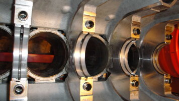
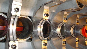
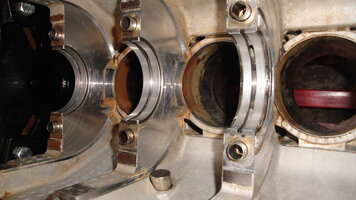
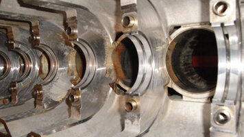
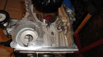
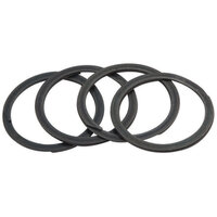
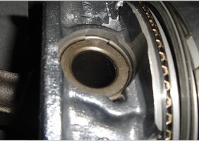
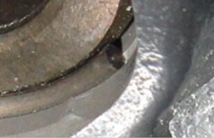
ENGINE SWAP: 2004 for 2002 GM ATLAS 4.2L MOTOR

mrrsm

Original poster
Lifetime VIP Donor
Supporting Donor
Member
Oct 22, 2015
8,272
Tampa Bay Area
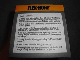
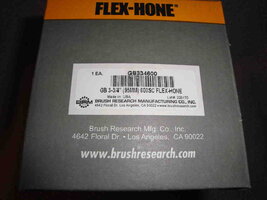
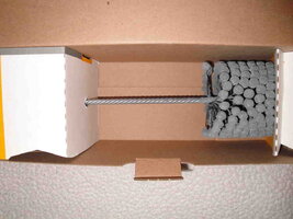
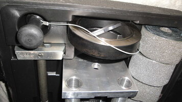
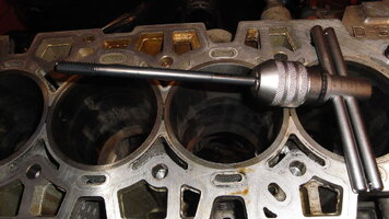
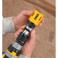
Well… After waiting damned near a full month… The 95 MM Flex-Hone Tool has arrived… and it seems a good time to mention that if you get this deep inside of your engine and after looking over all of the cylinders in your engine… you decide to do it the justice necessary by performing the Hone Out … These procedures should not give you the jitters any more than doing any of the other difficult tasks that have brought you this far along. The Beauty of the Flex-Hone is that unlike the complicated, gimbaled stones fixed inside of a huge Sunnen Boring Machine with oceans of coolant lubrication pouring inside such as used in the local Machine Shops… This tool is by far more gentle and forgiving:

http://s557.photobucket.com/user/60...BLAZERENGINEREPAIR/FLEXHONE95MM?sort=3&page=1

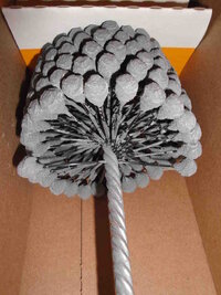
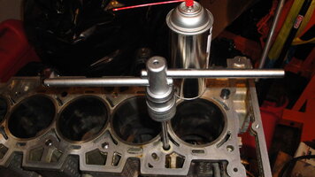
The design of the individual Carbide Nodules mounted on so many Flexible Nylon Stalks woven into central shaft of this tool means that as long as you align the tool essentially in the middle of the cylinder bore and start it turning before you move it down into each cylinder… The Carbide on Stalk design behaves as a Self-Centering device. Thus, it will take the worry out of any requirements for pre-mounting either the Engine Block or the Drill Head to any particular relationship between one another. You just have to properly prepare using either the requisite Flex-Hone Honing Oil that allows the removed metal particles to remain in suspension a little better… but Plain Old Organic 30 Weight Motor Oil will work just as well. It is NOT necessary to over-coat either the Cylinders or the Flex-Hone Tool with these lubricants… as the Hone will work Better if you are parsimonious with the stuff.

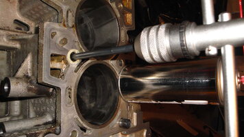
In the case of working the magic of this device on the GM Atlas 4.2L Engine… I’ll just tilt the block on the Engine Stand to about a 45 Angle, so that I won’t have to position my wrist in an odd way to negotiate my Big Drill in and out of each cylinder straight up and down at a right angle to the ground. I will only do a 10 Second Count at one in-out stroke per second when working each Cylinder to ensure doing the minimum amount of Metal Removal necessary to achieve a uniformly prepared surface inside each one.

I will also have applied Blue Painters Tape and Plastic coverings to all of the openings inside the Engine Block to protect the Open Journals and Oil Galleries from having any Oil contaminated with Metal Particles and Abrasives from getting inside of those places when such can so easily be prevented. These areas will need to be wiped down with Lacquer Thinner or Acetone and covered with removable tape. I like the idea of working discretely; and by that I mean… using the following steps for each individual cylinder and NOT trying to perform these actions on all (6) cylinders at the same time:

(1) Clean off all surfaces of the upper head with Lacquer Thinner or Acetone and use Blue Painter’s Tape to cover all Bolt, Oiling and Coolant Holes.

(2) Clean off all lower engine block Surfaces, Bolt Holes and Crankshaft Journal openings and cover them with Blue Painter’s Tape and Plastic Coverings.

(3) Use a small amount of Flex-Hone Oil and Hone out One Cylinder at a Time.

(4) Wipe out that Cylinder Clean of Oil saturated with Carbide and Metal Particles.

(5) Wash out that Cylinder with Hot Water and Soap &Flex-Hone Plastic Brush (Wash, Rinse...Repeat).

(6) Wipe out that Cylinder with non-fiber shedding Cloths until No Metal Residue remains.

(7) Coat down that Cylinder with WD-40 (NOT OIL!) to Prevent Rust.

(8) Cover and Tape that Cylinder Head Opening with Saran Wrap to Keep Out Contamination.

(9) Perform these tasks for All Six Cylinders and then clean up the Lower Block of any Residues.

(10) Wipe down ALL surfaces inside the Lower Engine Block with Lacquer Thinner or Acetone.

After doing this ... and Chasing and Cleaning Out All of the Bolt Holes… The Engine Block will be Ready for Re-Assembly.
 

mrrsm

Original poster
Lifetime VIP Donor
Supporting Donor
Member
Oct 22, 2015
8,272
Tampa Bay Area
Here is an Update from the Engine Block Prepping Activities from this Morning:

One of the most distracting realities about working on the Open Engine is that unlike a Cast Iron Block that you can practically take a Hammer and Chisel to in order to remove the Old Gasket Material, an All Aluminum Sleeved Block cannot tolerate such mechanical abuse. So What can You Do? Well… in the same Vein as a Drunk who uses the “Hair of The Dog That Bit Me...” Technique to Beat a Hangover… You can apply “Aluminum Vs. Aluminum” action in this situation and solve the problem.

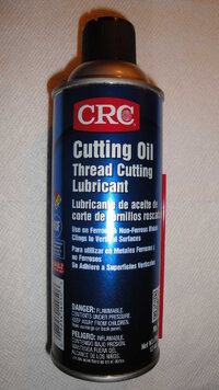
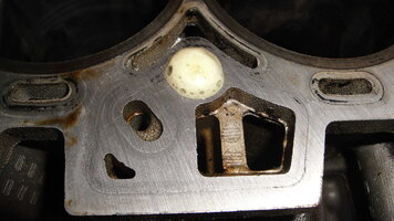
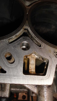
The idea here is to take a Big Swath of Aluminum Foil right off of the Roll and fold it in halves until you can make Swatches approximately 6” Square. Then Loosely Crumple them up until you begin to feel the little metal points being formed sharp enough to hurt your fingers… and Stop. Next… Get an Aerosol Can of CRC Cutting Oil and spray a small amount on one side of the “Aluminum Cotton Balls” and apply VERY LIGHT PRESSURE as you use them to gradually scrub all of the upper surfaces of the Engine Block. Do this as many times as needed to completely remove all of the Old Viton (Teflon) Gasket, Carbon Build Up and the Rusty Rings around the upper submerged rims and edges of the Ductile Cast Iron Cylinder Sleeves. Wipe the Block Clean Frequently.

Don’t be too concerned about damaging the surface of the Aluminum Engine Block, as the Aluminum Foil being used as a kind of “Brillo Pad” is PURE, Soft Aluminum…. And the Aluminum used in the Engine Block is an Aluminum-Silicate Alloy that is Harder, Tougher and Stronger that those “Aluminum Cotton Balls”. The Real Trick here though is that “The Technique” you use when working this surface block cleaning will make all the difference. Remember this… It is those Little, Sharp Cutting Edges that do all the work… so Light Pressure is Better than Too Much Pressure. And the other thing to do is to Throw Away the Used Polishing Balls as soon as they begin to flatten out and slide on the surface of the Engine Block. You will be amazed at just how good this technique will work... But you will have to go through quite a few of these 'scrubbers' before you finish cleaning the block.

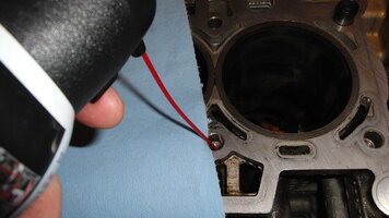
Please note that the staining from the Old MLS Gasket and the indentations left in the Head by the Metal Gasket Layers will still remain. However… The Engine Block will be "as Kleen as Kleenex" and you will not risk damaging the Engine while doing so. Keep a small Hemostat or thin Needle Nose Pliers as well as a Red Plastic Tube from a WD-40 Can to use to fetch out any Particles of shed Aluminum from the Water Jacket and Bolt Holes.

Here are some images I took of some "work in progress" partially cleaned up surfaces:

http://s557.photobucket.com/user/60...ZERENGINEREPAIR/ENGINEBLOCKPREP?sort=3&page=1

I’ll be making another post this afternoon that covers the removal of the Crankshaft and show how the Cast Iron “V” Blocks can be mounted on a section of Plywood Using Mechanics’ Wire and arranged to accept and support the Crankshaft for the ease of Prepping, Journal Polishing and Cleaning Up that needs to be done … Next.

More To Follow...
 
Last edited:

mrrsm

Original poster
Lifetime VIP Donor
Supporting Donor
Member
Oct 22, 2015
8,272
Tampa Bay Area
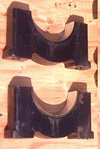
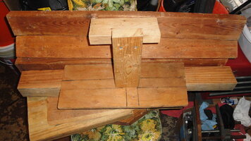
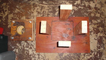
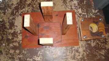
Okay… I’m guessing that I can’t be the only person interested in Prepping Crankshafts prior to installing them in their Engine Rebuilds so I’ll add in this data about a… Lets call This Thing “The Franken-Cranker” Work Station…LOL… which is nothing more than those Two Beauties (5” X 2” ‘V’ Blocks) mounted on a section of 1/2” Plywood with enough distance in between the blocks to accommodate the Crankshaft from out of a GM 4.2L LL8 Engine.

“The Franken-Cranker” Crankshaft Work Station Parts, Tools and Specs:

(1) 2” X 5” “V” Design Cast Iron Blocks
(2) Nylon (Lengthy) Zip Ties
(3) 18” X 30” X 1/2” Section of Plywood
(4) Assorted 2” X 4” X 5” Sections of Wood (to be decided if this is the way I want to go)
(5) 1/4” Wood Bit and Power Drill to Make Holes for the Zip-Ties
(6) Table Saw or Jig Saw to cut the Wood Supports to the Proper Dimensions
(7) 18” Metal Ruler, Carpenter’s Triangle, Tape Measure
(8) Assorted Screw Fasteners & #2 Phillips Chuck End
(9) Magic Marker
(10) A Long Straight Edge… A Carpenter’s Level will do…

Here are the “in-between” clearances necessary to be able to set the Crank right down inside of the ‘V’s’ and “Turn Too” on the Clean-Up and Polishing:

The Opening in the Bottom of the Engine Block is approximately 7”W X 23.5”L

The Crankshaft Assembly Spins just inside of a 7” Circle

The Exact Distance between the Inside Edge of the Front Crank Main and the Inside Edge of the Rear Crank Main is 23 3/8” as the Minimum Distance the Two ‘V’ Blocks can be to each other and not obstruct any part of the Crankshaft Assembly spinning in between.

The Crankshaft Centerline is approximately 3” above the Plywood Platform when resting on the ‘V’ Blocks… so in order to accommodate the freedom necessary to Rotate the Crankshaft, either the Centerline must Adjusted to a Height of 7” above the Plywood Base… Or an Opening as wide enough as a Perimeter Space must be cut-out in the Plywood Base to allow the Rotating Assembly Throws to maneuver around and not strike anything.

The former design raises the Center of Gravity for this thing considerably. The latter design would require that the Platform either have its own dedicated Open Rectangular Base be built and would be very stable… or it would have to be suspended between two level supports. Taking the time to build this thing will make taking micrometer measurements and doing the Journal Polishing a Helluva Lot Easier than just laying this thing on the counter for manhandling… or having to hold it in my lap. So I’ll ponder this a bit tonight and decide which of the two designs to finish with tomorrow.
Here are a few images of the initial layout:

http://s557.photobucket.com/user/60...NGINEREPAIR/CRANKSHAFTPOLISHING?sort=3&page=1

More To Follow...
 

mrrsm

Original poster
Lifetime VIP Donor
Supporting Donor
Member
Oct 22, 2015
8,272
Tampa Bay Area
I’ve said it more than once… “All Solutions… Breed New Problems...”

But every once in while… that Formula turns on its Ugly Head and critical thinking lets you do an “About Face”. I’d been mulling over which way to go with the design and fabrication issues of “How to Safely Mount, Clean and Polish a Nodular Cast Iron Crankshaft”… and without a doubt… there are so damned many ways to do this task; from the very, very expensive and exotic… all the way up to the most elegant, simple and in this case… Multi-Purpose Solution ever imagined. And so “Elegance and Simplicity” at a Reasonable Price once again have won the day... and so the design of "The Franken-Cranker" Work Station is decided. ;>)

The original problem was that in spite of having the correct 90 Degree Angle “V” Blocks to support the Crankshaft from the two extreme end Main Journals… the lack of sufficient height prevented them from allowing this Heavy Iron Thing to be rotated and polish all of the Crankshaft Bearing surfaces. In addition to the elevation issue was the second problem of preventing the whole mess become unstable and falling over while the work was being performed.

The most exotic and expensive tools ordinarily dedicated to this job are “Machine Shop Quality Treatment Tools” and are actually what is called for as this type of work is not usually done by the likes of me. Nonetheless… I had no intention of purchasing the needed Machine Shop equipment that starts at around $1,000.00 and just keeps going stratospherically skyward from there. The way I see it, the problem was Basic: Raise the Crankshaft Height to the proper level and keep it stable on the way up. I struggled with ideas about using everything from Blocks of Wood… to stacking loose 1-2-3 and 2-4-6 Precision Steel Bench Blocks that looked like Metal Swiss Cheese with 23 Holes drilled inside; 5 of them being 5/16” X 11 TPI, etc. Uh Uhhh… Nope… I was not going that route.

Next I thought about switching to using Steel or Cast Iron “cut-offs” thinking that remnants would be a lot Cheaper. Nope… NOT Cheaper. Same thing with Aluminum…. Somewhat less expensive… until you see the Arm & A Leg they wanted for S&H… Nope… FTN. So last but not least, I reasoned out that perhaps there was a ‘Readi-Made Tool’ I could use… though not specifically designed to solve this problem, perhaps one that would work well enough instead. Bingo! THIS one really Hit the Bullseye!


41%2BlLBxPqfL.jpg

The Base Dimensions had to be approximately the same as that of the “V” Blocks… 2” X 5”. Once again… Bingo! Among the Hobby Forged Anvils that are available in many shapes, sizes and weights, I found one that not only had the EXACT same rectangular area on the flat surface as the “V” Blocks, but also had the same overall width and the one of greatest interest to me also had Four slip-side Mount Bracket Points allowing it to be solidly bolted down. God’s Holy Trousers!

Now all I need to do is fasten the two “V” Blocks to the top of the matching 11 Pound Anvils with Mechanics’ Wire… as Snug as Two Bugs... and then Bolt the two sections up to my Work Table at the proper “Free Spin” distance in between the two Points. When I am done prepping the Crankshaft, I can just cut the Safety Wire and then all of the components can easily be disassembled and put up afterwards. You cannot ask for more than THAT! Lastly… On average, these sell individually for around $32.00 with Free S&H … so I didn’t go broke ordering two of them through Amazon:

https://www.amazon.com/Anvil/s?ie=UTF8&page=1&rh=i:aps,k:Anvil

http://s557.photobucket.com/user/60...NGINEREPAIR/CRANKSHAFTPOLISHING?sort=3&page=1
 
Last edited:

mrrsm

Original poster
Lifetime VIP Donor
Supporting Donor
Member
Oct 22, 2015
8,272
Tampa Bay Area
Okay… What with the recent but necessary distractions of working on building the Metal Shed in my back yard… I have not had hardly any time to get caught up with the latest work I’ve completed on the Engine. The Two 11 Pound Anvils arrived… and other than the fact that they were painted with a sort of “Ford 302 CID V8 Blue Enamel” and the thin casting lines indicates they were indeed Cast Iron Sand Molded items instead of having a “Fat Forging Line” and a ring to them when struck like True Forged Steel items would show. Nevertheless… for our purposes, these will do nicely.
Tomorrow’s efforts will be to use my HF 7” Cut-Off Grinder to carve out a healthy, heavy section of 3/8” X 30”L X 12”W Hot Rolled Plate Steel from a bigger section I’ve kept on hand for just such occasions. This plate will supply a sturdy base for “The Franken-Cranker” Work Station. Then I’ll lay the two “V” Blocks on top of the Anvils and separate them out on the Plate Steel to accommodate the Crankshaft Nose Journal on one side and the Flywheel Tail Journal on the other.

After marking their ‘footings’ for drilling out Four Bolt Holes per side… I’ll Drill, Tap and then Fasten down the Anvils firmly in place and then load the “V” Blocks right back on top. After gently placing the Crankshaft down on the two “V” Blocks and getting their alignments ‘plumb’, I’ll Safety Wire them to these Anvil Bases. These arrangements should well and truly serve to keep things in order while I have to rotate and move the Crankshaft around to polish each Journal “In Turn”. Here are a few images of these Anvils and I note that these would certainly make for One Hell of a Robust Set of Book Ends for the Heaviest Automotive Repair Manuals on anyone’s Book Shelf! ;>)

http://s557.photobucket.com/user/60...NGINEREPAIR/CRANKSHAFTPOLISHING?sort=3&page=1

Next we catch up on Today’s GM 4.2L LL8 Bottom End Disassembly Activities:

I’ve memorialized a decent Step-By-Step Photo-Play of the Removal of the Flywheel, Rear Crankshaft Seal Housing, the Crankshaft Bolts (… only Broke (1) Bolt on the Driver’s Side of Crank Main Journal #5 and I’ll extract it Tomorrow Morning), and the Aluminum Crankshaft Cradle. Then following on from Crank Main #1 to #7 moving from the front to the back of the inverted Engine, I marked a Plastic Zip Lock Baggie for the Outer Main Caps and left their Babbitt Bearings in-dwelling from each consecutive location as I used a 1/2” Drive 13 MM 12 Point Socket and Long Breaker Bar to gradually apply enough pressure to make each bolt “creak and slip” just a little bit each time working from the center out in an expanding oval until “All But One” of the Bolts broke free.

I took two images of a ridiculously long 3/8” Drive Extension I used like a “Speed Wrench” similar to the Old Wood Auger Drills were used long ago. I only point this out because if you want to “save your back” from excessive and unnecessary stress and strain while leaning over the Engine Block… Once the Main Cap Bolts are broken loose, by inserting the 13MM Socket to this Long Extension (with a nice-to-grip Knurled Upper Section) … you can comfortably stand straight up and by using the flats of both hands, you can rapidly “spin the bolts out” and get rid of a whole lot of tedium from having to slowly unwind so many fasteners while being being bent over this Power Plant.

I took some other intimate photos of the appearances of each Main Crankshaft Journal Surface and their respective Babbitt Bearings for later “Wear and Tear” comparisons that will be meaningful when taking Micrometer Measurements prior to performing any polishing. This approach helps to identify any trouble spots on their Journal Surfaces vs. “What The Mike Sez”. I note that each Main Cap is “Dot-Stenciled” on top with its respective Journal Number and each has an Arrow → indicating their correct orientation within the block. But since I like being as organized as possible… doing these extra steps makes for organizing things on a “White Table Cloth” just before Re-Assembly so much easier to get right. This is an Automotive Engine… Not a Tinker Toy… and when it comes to putting Engines Back Together and expecting them to Run… Cleanliness is Next to Godliness.

And so... it follows on that after the Crankshaft is mounted onto the “The Franken-Cranker” Work Station … and I have had the chance to ‘work it over’ to a Fair-Thee-Well… I’ll turn my attention towards cleaning up the insides of the Engine Block. I’m hoping that when the Big Barn Storage Building is finally erected and finished soon… I might be able to get enough junk moved out of my Garage to navigate about a lot easier and have more room to work and get this Engine back together:

More To Follow…

http://s557.photobucket.com/user/60...RENGINEREPAIR/CRANKSHAFTREMOVAL?sort=3&page=1
 

mrrsm

Original poster
Lifetime VIP Donor
Supporting Donor
Member
Oct 22, 2015
8,272
Tampa Bay Area
Okay… LOL… This is one of those days when I’ve discovered something about the GM Atlas Vortec 4.2L Engine that surprises even me! For last week or two, I’ve have had my Thinking Cap on Half-Cocked while trying to simplify the design of ‘The Franken-Cranker Work Station’... when the amazing solution to the problem was right there in front of me the whole time. When I say “Right THERE…!” that is EXACTLY what I mean! The ENTIRE DEVICE was laying right there on my work bench but I did not realize it was staring me right in the face ...until I turned it UPSIDE DOWN.

I am speaking of course of inverting the Crankshaft Cradle (GM calls it a LADDER) like a Turtle on its back and then using a Minimum of Two… possibly Three of the Crankshaft Main Caps that I had just Tagged and Bagged a few days ago as Inverted, Spaced Out Supports. When I realized what I might be able to do with these Engine Parts… I froze solid when the inspiration struck me. I could not get over that all I needed to do to construct “The Franken-Cranker" Work Station was simply use what GM had already built… and INVERT THE CRANK CRADLE… AND JUST BOLT ON TWO OR THREE OF THE INVERTED MAIN CAPS.

It was so obvious from looking at “The Thing” upside down that the necessary Angle Cuts in the Cradle to allow the Crankshaft Counter-Weights the Freedom to completely Rotate were already designed and built right into its Aluminum Casting… because they HAD to be. The correct distances and thickness of each Main Cap were also scaled to fitted and be bolted together … because they HAD to be. And in this case of using this Ready-Made Design, it occurred to me that I can use/install or move ANY combination of those Inverted Main Caps all along its length because the GM Engineers inadvertently had already designed The Perfect “Franken-Cranker” Work Station just exactly as I have described it.

I suspect that while creating this Unique Engine on a CAD Screen… they probably had no idea about what they had done! What an incredible discovery that the very parts they used to make up “The Bottom End” can also serve a secondary purpose for the Cleaning, Measuring, Polishing and Rehabilitation of The Crankshaft and all while riding upon its own original Babbitt Bearing Halves!

In order to confirm the L X W X H dimensions of the Fastener Hardware necessary to attach the Main Caps along the length of the Inverted Base Supports, I used my Digital Calipers and determined that the lower inverted Cradle supports were 30 MM thick, while the depth of the Main Caps at the Bolt Points was 65 MM. If you look at the below listed images… you can see that the “Inverted Cradle Arches” in between each set of Bolt Holes provides for multiple, stable resting point that will support the Crankshaft at a Dozen locations.

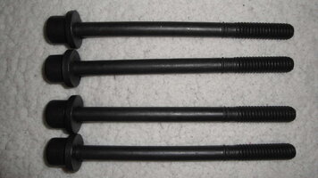
Also, you can see from the images that where there are open gaps where the Bolt Holes exit through the Inverted Cradle, there will be plenty of room for the attachment of a variety of M10X1.50MMX 150MM Bolts (or Threaded Studs) along with 4-6 Coarse Threaded Nuts and some Large Fender Washers to prevent any damage to the Aluminum Cradle Bosses or the Steel Main Caps once they are inverted and bolted securely together ...and then later unbolted and rearranged as needed.

upload_2017-4-8_0-51-4.png

upload_2017-4-8_0-51-54.png

Whether they were consciously doing this or not… what the GM Designers did here was nothing less than Brilliant!. And now ANYBODY can perform these same tasks without much more that a slight additional expense for the needed Fastener Hardware and no real difficulties in setting up the whole “GM Designed Franken-Cranker” up to do the job! Can You Believe THIS? I can’t WAIT to take some images of “The Thing” once I have all the parts cleaned and ready to try this out… LOL ;>)
 
Last edited:
  • Like
Reactions: webdawg

mrrsm

Original poster
Lifetime VIP Donor
Supporting Donor
Member
Oct 22, 2015
8,272
Tampa Bay Area
Okay... For all those who have been faithfully following (or perhaps I should say...wading through...) this monumental tome on all the various things that are involved in sliding over the edge of the "Engine Swap" precipice and disappearing into the Abyss that has become a Complete Engine Rebuild... Relief is on the way...

I received a PM from @Capote with a suggestion that I set up a Youtube Channel as MRRSM and instead of using "so many words" to describe everything in so much painful detail... instead ... reduce all of the verbiage to Videos on Youtube that will enlighten and perhaps even entertain in a less mind-boggling manner. I took his suggestion seriously to heart and if you compare EVERYTHING that I wrote in my very last post with the content of this attached link to my New Youtube Channel as the First MRRSM GM 4.2L Engine Rebuilding Video...you will understand what am going to try to do from now on regarding this major project.

The only outstanding question is whether I will have to post the Video content elsewhere on GMT Nation or if I can get away with just a few brief explanations about the relevance and content and keep posting here on the same involved topic. Here goes nothing, Guys.... Please let me know what you think ...and 'like' the videos over at Youtube if you do. :>)


More to Follow with the actual USE of this thing....
 

mrrsm

Original poster
Lifetime VIP Donor
Supporting Donor
Member
Oct 22, 2015
8,272
Tampa Bay Area
On April 24th, 2017... My wife took a serious misstep off of our concrete sidewalk and after falling headlong into the yard and landing on her upper right shoulder... after refusing to visit the Doctor for four days until her arm started turning black from the severed blood vessels... I practically had to hogtie and drag her to my own Sports Medicine Physician. The X-Rays revealed that she had completely broken the Ball in the Socket off of her upper right Humerus and ever since then... with the exception of a few scattered occasions in the wee hours of the morning... pretty much all of the work being done on the GM 4.2L LL8 has had to be set aside while I've been attending to her needs.

But now that the bones have knitted well and are almost completely healed, with her mobility gradually returning and her rehab also showing proof of good healing and range of motion... I can soon set aside my "Domestic Goddess & Nurse Crown" and "Turn Two" once again on the Engine Rebuilding Project. I swear to God... If it Hare-Lips Governor 'Skelator' down here in Florida... I intend to complete this engine... come Hell or High Water. Jesus Palomino… If only the lives we lead were linear... so much more could be accomplished.

In my next Video... I'll lay out all of the brand new internal components and do a walk through that will De-Mystify much of what they do and how much their acquisition will cost and how these parts must be handled during their installation. This will later serve to let me focus the consecutive videos strictly on their individual installations into the Engine... without getting lost in the weeds with added 'Techy Stuff' about the parts, their sourcing or numbering, etc.

Today... My son and I went to the local Florida DHSMV and I finally got the chance for us to swap titles, tags and registrations that will make him the proud owner of my 2003 Chevrolet Silverado 1500 4.8L White Pick Up Truck with a clean and unencumbered title. And I will once again be the titled owner of this 2002 Chevrolet Trailblazer LS. He has a great new and better paying job, but it means that he and his family must relocate right up to the edge of the Florida-Georgia border. So it made sense to get him squared away with a reliable and useful vehicle prior to leaving this coming Friday. I'm going to miss him and my grandchildren more than these poor words can say. And so, henceforth that is my plan and promise that I'll try to get back in the saddle and stay on this horse all the way to the finish line.
 

mrrsm

Original poster
Lifetime VIP Donor
Supporting Donor
Member
Oct 22, 2015
8,272
Tampa Bay Area
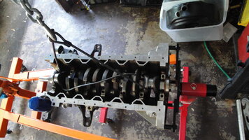
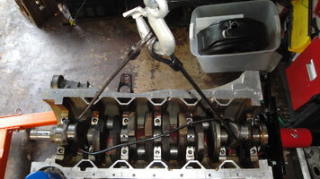
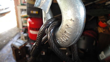
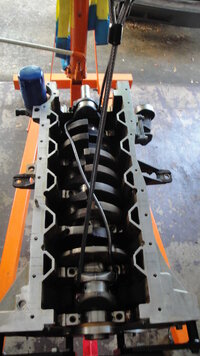
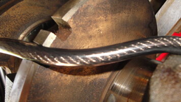
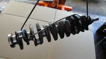
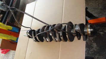
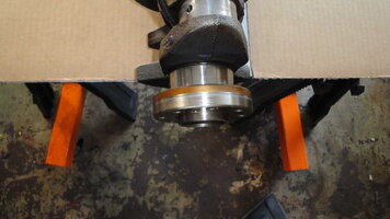
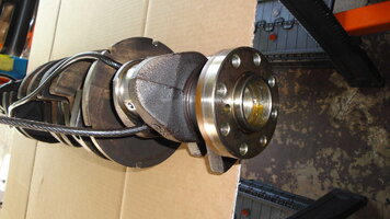
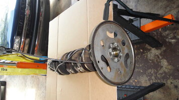
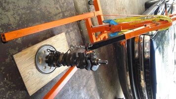
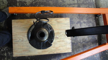
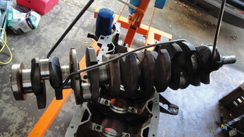
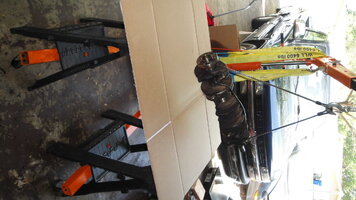
Forgive the long hiatus from this project… but as we all know… Things you want to accomplish in Life often get interrupted and side-tracked from time to time… just by the processes of Living it. Due to some caution needed by this 'Old Man' when handling heavy, asymmetric objects... I thought about this for quite a while and finally decided to apply Archimedes' Ideas of leverage to very gently lift this VERY Long Crankshaft up and out of the GM 4.2L Aluminum Engine Block without the need for straining my back or risking damage to either the Crank or the Block. To accomplish this without a lot of fanfare... I used a Vinyl Coated, Swage-Looped Cable from a Bicycle Lock Set that I had sitting around for a few years. Lo and Behold... It threaded safely around the Journal Crank Throws and cinched up to the Engine Hoist Hook perfectly in such a manner that on one end... the cable nestled itself inside of one of the Reluctor Wheel Notches and stabilized it as I very slowly applied the lift force a bit at a time until I had the Cherry Picker Hoist aligned perfectly and at the right moment for taking all of the weight with balance... one tiny crank of the Handle and it literally floated loose from the Engine Block.

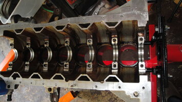
I was very surprised to find that just as with the bearings inside of the Main Caps... The Upper Block side Main Bearing surfaces were hardly worn at all; even after 160,000 Miles or so. It would seem that the 70 MM Bearing Race Outside/Inside Diameter surfaces multiplied by Seven (7) Main Bearing placements manages to divide up the horrendous rotational and torsional forces being applied by the six place Rotating Assembly into the bottom end quite well enough to stay within their proper dimensions and minimize wear and tear. It is worth noting that as a Rule… Crankshafts should NEVER be allowed to be propped up on either end ...like it is sitting on Two Bridge Abutments, as the middle area will begin to sag and place a bend or a curve in there the likes of which can only be compared to an English Long Bow and eventually, ruin the Crankshaft unless it is later laboriously heated, struck with a small Sledge Hammer and then straightened up again.

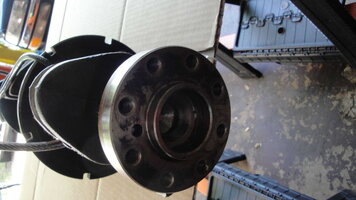
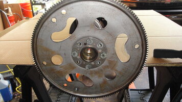
The best action to take is to mount the Crankshaft into an Old Flex-Plate or Flywheel ...in this case using Four (4) Bolts in a cross pattern for support and stand the Crank on its End. Doing so makes the job of polishing the Journals with a mild metal polish and smooth construction paper wrapped uniformly around each journal and then spun carefully and uniformly with a double wrapped Sneaker Shoe Lace to polish the Hell out of all of those Journals ...and not remove too much Metal.

I took some images of the steps involved and these show that one can use that Big, Clumsy Engine Hoist and a length of Vinyl Covered Coiled Cable to solve an otherwise difficult problem for two people, let alone only one person trying to handle. It is important to realize that the majority of the edged and right angle surfaces at the bottom of the block have to be almost Razor Sharp and if one were to mishandle this Long Crankshaft when either pulling it out… or placing it back into the Long Block… one could easily crush fingers, receive serious metal cuts… or at the very least, risk damaging the Crankshaft Journals and Brand New Bearings if either haste or misfortune were to follow on with these delicate in and out movements.

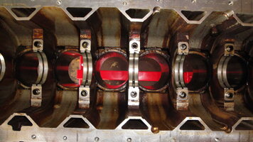
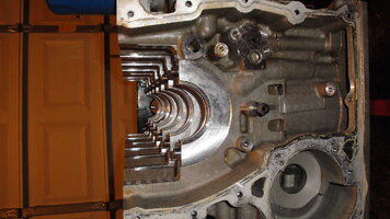
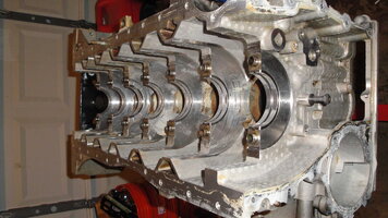
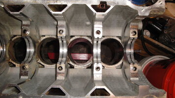
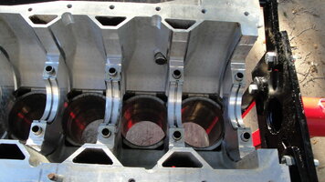
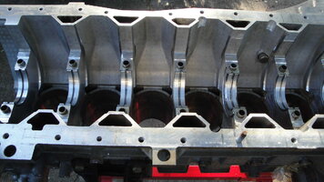
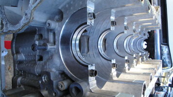
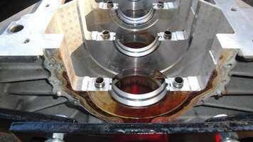
The empty GM 4.2L All Aluminum Engine Block is a remarkably naked and wide open space at the base where the Heavy Cast Aluminum Crankcase placement is so vital to enclosing and strengthening the upper engine. Of necessity, it is definitely a structurally sturdy and robust other half of “The Clamshell”. Contrast this engineering effort with that of the mere Mild Steel Factory Pressed Oil Pans of yesteryear and you can get a better idea of just how remarkable this motor really is:

http://s557.photobucket.com/user/60...ZERENGINEREPAIR/GM42LCRANKSHAFT?sort=2&page=1

Next in line… I have either one or two Broken Main Cap Bolts that were broken off when I was removing the Cradle Bolts. Unlike my past exotic forays into so many self-inflicted mistakes during the removal of the Old Head Bolts on the In-Dwelling 2002 Engine Head Removal… I actually have the correct OEM GM Tool-Drill Blue Steel Guide to use with a Reverse Twist Drill Bit and reduce the possibility of doing any damage to the 2004 Engine Block. As this progress continues to move forward, cleaning up and dressing the Crankshaft, cleaning out the entire Engine Block and then honing the Cylinder Walls after those tasks are completed will follow on.

DSC01741.jpgDSC01742.jpgDSC01743.jpgDSC01745.jpgDSC01747.jpgDSC01748.jpgDSC01756.jpgDSC01757.jpgDSC01759.jpgDSC01760.jpgDSC01761.jpgDSC01762.jpgDSC01765.jpgDSC01766.jpgDSC01768.jpgDSC01770.jpgDSC01771.jpgDSC01746.jpgDSC01758.jpgDSC01750.jpg
 
Last edited:

mrrsm

Original poster
Lifetime VIP Donor
Supporting Donor
Member
Oct 22, 2015
8,272
Tampa Bay Area
Okay… Considering how drastically sideways many Engine Block Bolt Extractions can devolve into, this one turned out to be a breeze. And since this work involves an Aluminum Block… the way this thing progressed and with the rarity of any Complete GM 4.2L Engine Tear Downs, following these Guidelines will help you to keep the job simple; but only if the LL8 being worked on is mounted on an Engine Stand. You’ll have to open up a ‘Fresh Can of Patience” too for this special job:

(1) While it is NOT entirely necessary to have the Crankshaft Removed when doing this work, it will help to clear out the work area and eliminate a lot of clutter if you don’t start this work until the Cradle, Main Caps and Crankshaft have all been taken out. More than likely… if you’ve Broken Off a Cradle Bolt… you’re either in the middle of a Tear Down and attempting a Complete Engine Rebuild or you’ve Snapped Off one or more Cradle Bolts during Re-Assembly due to one or more of these reasons: (A) Failed to Chase the Bolt Holes and really clean them up inside of the Upper Block… or… (B) Failed to use a very small amount of ARP Engine Fastener Lube on each New Bolt and follow the Torque Procedures and TTY Finishing to the letter… slowly and carefully.
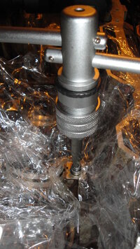
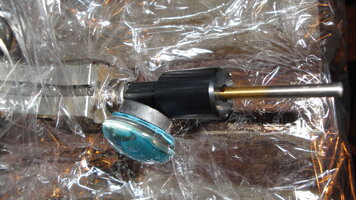
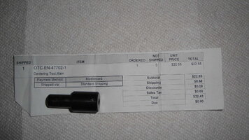
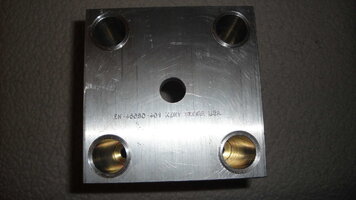
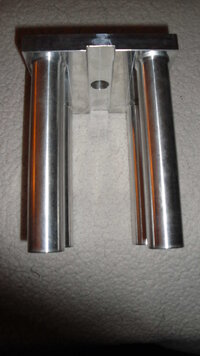
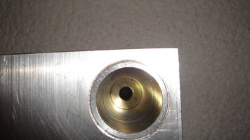
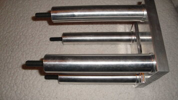
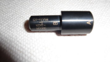
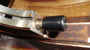
(2) While GM offers an OEM “Kent Moore Crankshaft Bolt Extraction Kit” for around $500.00 … OTC sells a Dual Purpose Drill Bit Guide EN-47702-1 that will come in mighty handy not only for Extracting the Cradle Bolts… but when Flipped over… the ‘Fat End” will serve to guide the same Drill Bit for the removal of the 4.2L LL8 TTY Head Bolts as well… and only at the cost of around $25.00 or so. Then using any standard “Right Hand Thread” Bolt Extraction Drill and Carbide EZ Out Bit Kit will do the job for you quite nicely.
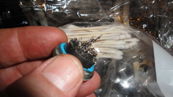
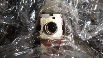
(3) It really isn’t necessary to use a Name Brand Cling Wrap for this next requirement… but I prefer using Saran Wrap to cover up everything nearby inside and around the Engine Block area prior to beginning the Bolt Extraction process. Trust me here on this one… With the Engine Block in the inverted position while doing the requisite Drilling out of the Bolt Shanks in preparation for using the EZ Out Carbide Steel Tool(s) … the very LAST thing you want to have happen is to accidentally drop Hardened Steel Shavings down inside of Open Oil Galleries. As soon as they get hit by 65 PSI of Motor Oil… Those that razor sharp metal pieces will be forced right back down into the Aluminum Babbitt Bearings where they can easily carve into the outer surface of the Crankshaft Journals and eventually destroy your engine. So Before you start, cover everything up with Saran Wrap and afterwards, sweep a Magnet over the surface of the Cling Wrap and get every last bit of metal. Then roll the cling wrap stuff from the outside in like a ball and get rid of it.

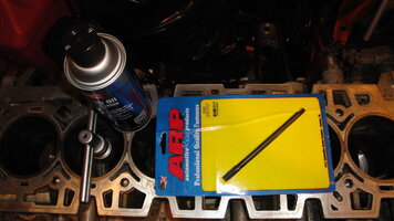
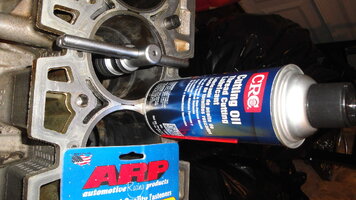
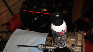
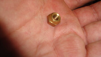
(4) At the Start… Center Punch an impression Dead Center on the Broken Bolt Shank Face by using a Brass Acorn Nut from a Plumbing Kit to act as a Centering Guide for the Center-Punch and give it a careful, single hit with a Ball Pen Hammer. Then… Insert the OTC Drill Guide into the Stainless Steel Tube at the Top of the Bolt Hole and use either a spray of Machinist's Cutting Oil or Motor Oil to help keep control of the Metal Shavings and cool the Regular Tight Twist Drill Bit. Use a Variable Speed Drill and allow for Short, Controlled Bursts of Drilling...and then STOP! Remove the OTC Guide and Clean out the Drill Hole using a Magnet covered with a Shop Towel OFTEN! Hold the Magnet Towel over the Drilling Hole and use ‘Canned Air’ to drive out all of the Shavings into the cloth and Magnet. DO NOT RUSH! This process is time consuming… but the Shavings will rapidly collect under the OTC Guide and chew away at the Bolt Hole Threads in the Block.

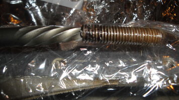
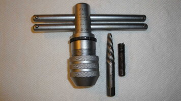
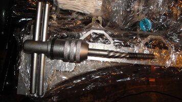
(5) As soon as you finish with getting deep enough into the Broken Bolt Shank… Remove the OTC Drill Guide and shift to a Larger Drill Bit from the Kit consummate in size to be able to drill to within 1/16th” of the outer Thread Line of the Broken Bolt Shank. Once you have drilled deep enough to allow the EZ Out Carbide Tool to get a decent “bite” down in there… Set up your Bit Holding Handle at a Right Angle to the Broken Bolt and after inserting the Carbide Bit down inside of the Bolt as straight as possible… apply moderate downward pressure while slowly turning the handle Counter-Clockwise. This may take a few downward tries to get the tool to grab and hold… but soon the broken off piece inside of the block will yield and it will only require very light pressure to unscrew the Bolt Shank the rest of the way out of the block.

(6) When you finish... Clear all of the Tools from the Work Field BUT DO NOT USE THE CANNED AIR TO SPRAY AROUND THE ENGINE. Run the Magnet around the Work Field a few times to pick up as much ferrous metal sprue and cuttings as possible. Spray out the offending Bolt Hole using the Magnet/Shop Rag technique, then start lifting and folding the Saran Wrap from the Outside of the Block inwards and gradually gather it all in the center and lift the whole ball out and away from the engine block. Don’t Leave or Use Cheap Red Shop Rags from HF down inside of the Engine as they shed way too many red fibers that will be difficult to get out of and off of the engine interior spaces. Use Lint Free Blue Shop Towels only for cleaning up:

DSC01785.jpgDSC01791.jpgDSC01793.jpgDSC01797.jpgDSC01799.jpgDSC01808.jpgDSC01809.jpgDSC01812.jpgDSC01813.jpgDSC01815.jpgDSC01816.jpgDSC01774.jpgDSC01791.jpgDSC01795.jpgDSC01799A.jpegDSC01805.jpgDSC01808.jpgDSC01811.jpgDSC01772.jpgDSC01797.jpg

http://s557.photobucket.com/user/60...ZERENGINEREPAIR/GM42LCRANKSHAFT?sort=2&page=2
 
Last edited:
  • Like
Reactions: midnightbluS10
Feb 18, 2017
109
Shreveport, LA
MRRSM, I just want to say that I love your posts. They're always so extremely informative and full of information, tips, and tricks. Thank you for taking the time to document all of this. I know just how much more work that adds and I just want to say I'm extremely appreciative of the time and effort you put forward to do it. Thanks!


Edit #1: The black centering tool...i almost bought one of those when drilling out the head bolts to use as a drill guide to keep the bit centered. I think they were actually called drill guides, at least the ones I had was looking at, which looked exactly like that.

Edit #2: guess I should've kept reading lol. Sorry! I actually had the same idea to use an acorn nut over the hole to center the punch and drill bit because I didn't buy the guide. Glad to see I had the right idea.

Are you planning on honing the 2004 block with a ball hone or are you having it done at the machine shop with the correct machinery, etc? Also, that crank stand you made is ingenious! Nice!
 
Last edited:
  • Like
Reactions: mrrsm

mrrsm

Original poster
Lifetime VIP Donor
Supporting Donor
Member
Oct 22, 2015
8,272
Tampa Bay Area
I will be using the 95MM Ball Hone designed by “Flex-Hone” to dress up the 93 MM Cylinder Walls and augment this action by using Machinist’s Spray Cutting Oil in order to keep the Ceramic Nodules well lubricated and capture the Ceramic and Metal effluvia in the sticky oil that will be minimally removed. It is important to know that the Outer Diameter of the Flex Ball Nodules will change as the device wears out slightly during each use per cylinder… so cleaning off the Flex-Hone after each round of action is necessary to try to balance its performance from Start to Finish… from Cylinder (1) through Cylinder (6). Do NOT wipe down the Flex-Hone with ANY solvents as the Flex-Hone will be destroyed. Likewise… Do NOT wipe down the Cylinder Walls with any solvents, either.

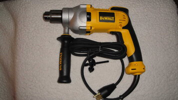
While paying a professional for this action might prove necessary if the Cylinder Walls are badly scored and in need of having no more than 0.010 MM of metal removed… since the Chilled Steel Sleeves of the GM 4.2L LL8 Engine Block are only 1.5 MM thick and the Compression Ring pressures found inside of these engines is fairly low… it is only necessary to make 10-20 in-out passes within the range of 500 to 800 RPM with a well-lubricated Ceramic Ball Hone chucked inside of a Large 3/8” Variable Speed Drill WITH THE HANDLE ATTACHED to achieve a de-glazing refreshment and clean out of the cylindrical surfaces ending with a proper 45 Degree Cross-Hatch Pattern. The 600 Grit Size I am choosing to use here is very appropriate for use with New OEM Moly Rings and to ensure they re-seat and seal properly once the Engine is buttoned up and ready to run. I am paraphrasing here… but I believe that @Mooseman has provided the very best instructions for Breaking In the Newly Re-Manned Engines on numerous occasions with the need to“...run the Engine HARD through a series of rapid accelerations up to around 35-45 MPH ...and then use gradual decelerations to achieve the best Piston Ring to Cylinder Wall sealing.” (Perhaps he can add and refine those instructions as necessary.)

Besides a careful, rhythmic hone speed to achieve the proper angle for the Hone Beads inside of the cylinders is how fastidiously they must be cleaned afterwards to remove all traces of the Gray Ceramic Powders and Metal Particles that will be present once the honing job is done. Without ensuring this Spanking Clean relationship between the New Piston Rings and the Cylinder Walls, you can just bet that the Rings will NOT seat properly and a loss of compression will be the result.

While I do not believe that the process of Honing the Engine Block should be relegated strictly to a Machine Shop… such specialty machining actions requires the utmost attention to details that one would not even bat an eye at if the these delicate Aluminum Engines were made out of Good Ol’ Cast Iron. It follows that in the hands of a “Careless Mechanic”… a Cylinder Hone… even one as innocuous and user friendly as this Self-Centering Flex-Hone Tool... can wreak havoc in very short order.

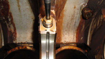
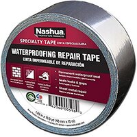
There is another consideration that I think I have an answer for that has probably never been tried before: Aluminum Tape. Nashua manufactures a very thick mil sized roll of “Gluey Aluminum” that, when applied to cleaned surfaces in laminations... provides the means to cover practically anything that it can stick to with a Water-Proof, Rust-Proof Semi Permanent surface. In this case… I need this tape to act as an “Aluminum Shield”. I've observed that the thick Aluminum Block Main Buttress Uprights will be immediately exposed to the action of the Spinning Ceramic Balls as soon as the Hone passes through occasionally at the bottom of each Honing Stroke and I stress that they might become damaged as a result. So just as a Precautionary Measure… I’ve decided to cover all of the areas adjacent to the opening inside of of the Engine Block where each of the Chilled Steel Cylinders dwell with a few sturdy layers of the Nashua Heavy Mil Aluminum Tape and prevent the possibility of them coming to harm by the battering from the Ceramic Ball Hone.

61kLI5Td53L._SX385_.jpg

https://www.amazon.com/gp/product/B0047XXZ7Q/?tag=gmtnation-20

Additionally… any and all areas that would ordinarily be exposed to the awful cast-off of sticky ceramic-steel leftovers flying around and out of each cylinder will also be covered and taped off with Saran Wrap and Blue Painters’ Tape. This might seem a bit extreme, given that most engine blocks will require a very vigorous cleaning of each bore with Hot Soap and Water just after being honed and then lightly blown out with compressed air afterwards… But I'm NOT taking ANY chances with the possibility of introducing what amounts to a “Liquid Ceramic Abrasive” getting all over and “into the innards” of this Engine.

One last reminder about what happens when you Wash Cast Iron in Very Hot Water: The Cylinder Walls will instantly Rust Up a Bright Orange if you do not spray them all down IMMEDIATELY upon completing this “Wash, Rinse… Repeat” Cycle. So have a New Can of WD-40 right at hand and at the very INSTANT the water is off… Spray down the inside of the Cylinders with the stuff. There will be no need to worry about what happens to all the water dripping down from inside of the Cylinders… Just use compressed air and blow out the water as you lightly spray down the inside of each one. My suggestion is that after Honing Each Cylinder… LEAVE THEM COVERED WITH THE CUTTING OIL… and only work on Deep Cleaning Out each Cylinder… One at a Time. Doing it this way will allow you to feel much less like W. C. Fields felt during his famous ‘Cigar Box Juggling Act’ and ensure that all of this work becomes worthwhile:


http://s557.photobucket.com/user/60...BLAZERENGINEREPAIR/FLEXHONE95MM?sort=3&page=1

An Ounce of Prevention… is Worth a Pound of Cure...” Benjamin Franklin

DSC00653.jpegDSC00655.jpegDSC00656.jpegDSC00657.jpegDSC00658A.jpegDSC00659A.jpegDSC00659.jpeg
 
Last edited:

mrrsm

Original poster
Lifetime VIP Donor
Supporting Donor
Member
Oct 22, 2015
8,272
Tampa Bay Area
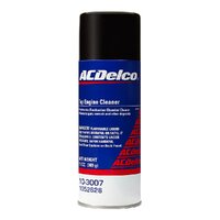
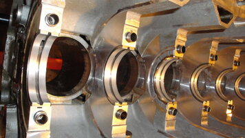
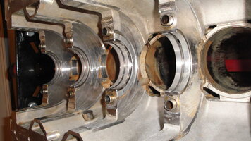
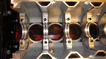
These Images cover the cleaning I performed using a Full New Can of ACDelco Top Engine Cleaner and some Scott Lint Free Shop Towels (...or pretty damned close to it…) and some 11Mil Nitrile XX Size Gloves. For the sake of your Health and Safety… Move the Engine Stand into “The Great Out Doors”. In my case… a bit out into the Driveway for my Work Space. Bring along a very large Can of "Elbow Grease" as these things are the necessities for cleaning up the entire inner, lower GM 4.2L Engine Block of about 160,000 Miles worth of Oil and Gas Vapor Varnish.

By the way…Where is your OSHA Approved Chemical Protection Breathing Mask and Wrap-Around Eye Protection? If you don’t have these… You’d better think about getting them ...well B4 you even start to spray that awful stuff.

It takes a few passes of shaking up the Spray Can and Foaming up and spraying down small portions at a time... but if you start at one end and don't allow too much to drain off wastefully… by soaking the stuff up in the Blue Shop Towels and then scrubbing all the weird inner cubbies and hiding places, you will find that this Top Engine Cleaner will do the job proudly. Have a care not to get your hands and fingers cut to ribbons on the razor sharp edges around everything down inside there. By the time the First Pass is done... you'll be ready for the next one… But for God’s Sake… WALK AWAY FOR A Ten Minute Break and avoid breathing these fumes as much as possible.

It can't be good for your Liver and Kidney(s) and Lungs as the 'Organs of Elimination' ( ...as well as the lipids holding things together inside of your Brain)... by having this solvent migrating through your bloodstream after breathing in the vapors too much. So take frequent breaks and remember that doing this inside of your Garage is a Very Big No-No. After you have thoroughly cleaned and wiped down the Engine Block ‘Innards’ ...and Before you Drag the Engine Stand back into the Garage to call it a day… use a Very Large Garbage Bag to slip over one end of the Block and secure it at the stanchion upright with a few twists and turns and then gently set something heavy enough on top it to keep the bag tightly closed. Don’t open that bag inside of a Closed Garage… push it outside again to do anything else on it until you can really spray it all down with Brake Cleaner to remove the rest of the residue…. Again Out Of Doors!

If you failed to heed the original health warnings and suggestions… by now...you will probably have a Very Bad Headache that will last for a few hours afterwards and wish that you HAD worn that OSHA Industrial Grade Breathing Mask you bought at Lowes or Home Depot before you started this job… so give your a body a 24 Hour break from using any more of this ACDelco Top Engine Cleaner… and from now on... avoid the health problems that can happen after being exposed to way too much of this stuff… way too often. Drink Plenty of Water to help flush all of that crap out of your bloodstream, too.

Next up will probably involve me going over the Engine Block with a Fine Toothed Comb looking for any Cracks in the Main(s) Buttressed Webbing and Cylinder Walls while the uncommon opportunity to do so prevails. If this were a Cast Iron Block I'd probably have it Magna-Fluxed for Cracks and Deck the Head(s) slightly to ensure the Block is quite Flat, Square and ready & willing for this Engine Rebuild. But, being that this LL8 Motor is an All Aluminum Chunk of Non-Ferrous Metal… it prompts me to use my 'New Eyes' and a Bright Flashlight to thoroughly inspect this thing… Just One Last Time… before the Cylinder Honing and follow on Engine Rebuilding Fun can ensue:

http://s557.photobucket.com/user/60...RENGINEREPAIR/GM42LBLOCKLEANING?sort=3&page=1

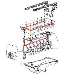
LINTFREESHOPTOWELS.jpegDSC01854.jpgDSC01852.jpgDSC01851.jpgDSC01848.jpgDSC01846.jpgDSC01845.jpgDSC01844.jpgDSC01843.jpgDSC01842.jpgGMLL8OILFLOWPATH.jpegDSC01838.jpgDSC01837.jpgDSC01835.jpgDSC01831.jpg10-3007.jpgDSC01850.jpgDSC01849.jpgDSC01847.jpgDSC01841.jpg
 

mrrsm

Original poster
Lifetime VIP Donor
Supporting Donor
Member
Oct 22, 2015
8,272
Tampa Bay Area
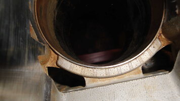
Okay… Having done a very critical check-over of this LL8 Engine Block… I have discovered a serious problem with at least one of the Cylinder Liners that will go a very long way in explaining the repeated complaints we have read about time and again involving “Piston Slap” noises coming from these aging engines that probably had to do with the GM Engineering decision to keep the length of the Piston from Crown to Skirt a bit shorter than they should have when they designed it. This was likely done in order to try to shave weight off of the Rotating Assembly and keeping the Piston to Wrist Pin Bores from 'ovaling' out at over 6,000 RPM.

Here is the Specific Issue:

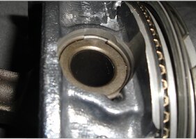
Just before the LL8 Pistons reach their TDC (Top Dead Center) positions… as the Crankshaft Journal achieves its last little bit of “angular tug” on the Connecting Rod… The Piston Skirts try to "Rock" and Cant Towards the Direction of Rotation… while at the same moment the upper portion of The Piston Head rocks in the same manner, sort of "double digging" into the upper Cylinder Walls. Considering that these engines can achieve a Very High Mileage Endurance Level of over 300,000 Miles (NOT Kilometers…) it is no wonder that over time, the tendency to wear in grooves and channels in the shape of the Piston Tops and Skirts into the bottom of the Gray Cast Iron Sleeve these repetitive actions eventually succeed in digging out Crescent shaped grooves into the Cylinder Wall. These eventually allow the extending Con-Rods to “Pop” the Skirt against the same Wear Spot ...again and again until it wears itself inwards deeper and deeper over time. Hence… The Famous Sounds of GM 4.2L “Piston Slap” at idle and Cold Day Start-Ups.

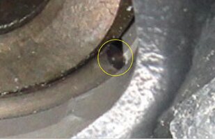
But that is not the only Artifact of Injury that occurs when this is going on: The other action involves the opposite edge of the Piston and Rings to trying to “Snap and Polish” the area it approaches at nearly 3/4’s of the way towards the bottom of the cylinders; nearly at BDC. And the last Artifact to add insult to these accumulating injuries is in this phenomena that this very same thing occurs nearly at TDC… where you can see a 2”-3” long Gray Oblong Dimple being carved into the upper cylinder walls in the same side as at the bottom, just before the Piston reaches TDC; but NOT as highly pronounced.

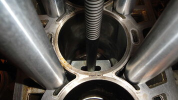
Well ...you might think that with such “Thin” 1.5MM thick OEM Cylinder Sleeves placed in these engine blocks starting over (16) Years ago … and two years later on when this Donor Motor was Brand New that Maybe… JUST Maybe… it could be honed out right now to a reasonable dimension. But L’ll tell you this: If the “ledge” that I felt down inside of that cylinder was on the side of a Mountain… and I had to use it as an emergency hand-hold to keep from falling… it is a BIG enough Ledge… that I’d stake my life on being able to take hold of it and get a good grip with my fingers.

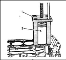
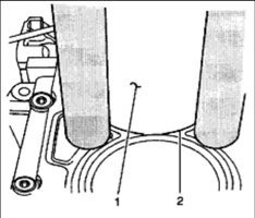
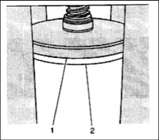
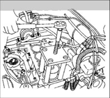
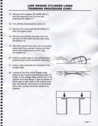
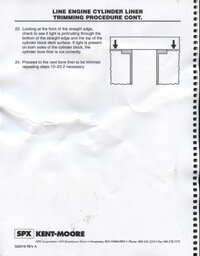
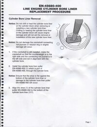
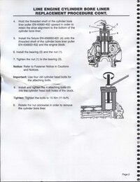
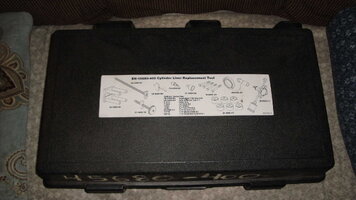
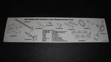
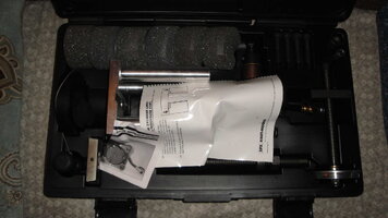
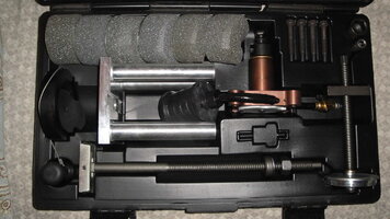
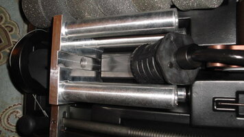
The long and the short of it is this: If it were a Cast Iron Block… I’d Bore out the Block by at least 0.030” (0.075 MM) and get Pistons and Rings to match this change. But since this is an LL8 Block, I think we’ll just proceed with Completely Replacing the Cylinder with a Fresh One from Melling… Instead. I know… I know what you’re all thinking… “OMG ...BOBBY… WTF?!!!” But Guys… Breathe EZ Here Fellas… This is actually something that any one of us can do; Hell… Even right there inside of the Engine Bay… if that was necessary. But for us though, with having this Clean and Tidy LL8 sitting on an Engine Stand, Naked as Jay Bird… This will be much easier to do than you think. Of course… this job DOES require a VERY SPECIAL TOOL KIT to accomplish. But I’d rather NOT pay a Machine Shop the $1,500.00 they would charge to sleeve all six cylinders. Instead… We’ll be using the Specialty K&M OEM Tool Kit… and start with replacing just the one FUBARed Cylinder Sleeve with a Brand New Stock One that sells for $29.79 Plus S&H from RockAuto.com.

Here are the images of this Kit:

http://s557.photobucket.com/user/60...NGINEREPAIR/GMCYLINDERSLEEVEKIT?sort=2&page=1

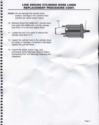
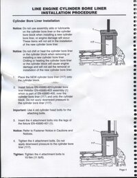
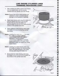
Unlike the “Chilled”, Centrifugally Cast Gray Iron investments of yore that were put into this LL8 Motors by GM back at the Factory so long ago, these procedures need Neither any “Chilling and Freezing Down” Nor the use of ANY Chemicals or Adhesives to accomplish this “Startling Sleeve” R&R. It just takes the Right Tools… the Right Manual and some Good Images as guides as to how to get this job done in short order. And just so you all know… The FIRST GM Dealership Billable Hours Charged for the Labor for only One Cylinder repair (among many others added to the Bill) comes in at around (15) Hours. This must be for covering all of the Tear Down To Gain Access problems and the Set Up Time for this R&R. BUT after that… they only Charge 0.6 Hours Labor for the remaining (5) Cylinders to be removed and have the New Sleeves installed.

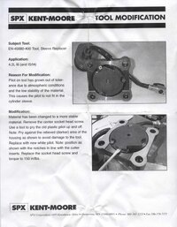
Now I will admit that this particular Kit IS very expensive if you have to pay Top Dollar for it at around $700.00… not including any New Sleeves. But I found a complete and seldom used Kit for $275.00 S&H Included on eBay today… So I grabbed that one and ordered only the One Melling Cylinder Sleeve to fix the Most Offending Cylinder… and if that goes swimmingly well… We’ll do the rest of them. :>) … Oh… Better Skip the Kits being offered for around $175.00… They look to be missing Half The Parts… and you cannot afford to have ANY of the Kit Components missing or you will never finish the job. But if you are in the middle of a Complete LL8 Rebuild and want to go “Whole Hog” on your Project… there are still a few of these complete kits on eBay selling for around $300-$400.

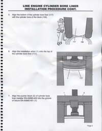
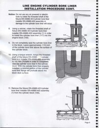
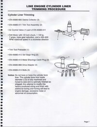
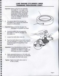
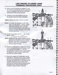
Here are a few “How-To” Instructions and Technical Help for this Using This Cylinder Bore Sleeve Removal and Replacement Tool Kit:

http://www.enginebuildermag.com/201...n-procedures-for-2002-2006-gm-ecotec-engines/

http://enginetechcatalog.com/images/Bulletins/TB 2220.pdf

https://www.justanswer.com/car/10ryb-just-experience-piston-slap-noise.html

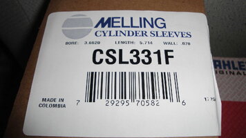
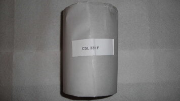
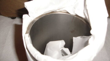
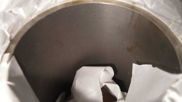
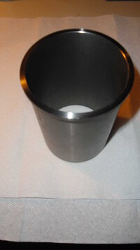
The GM LL8 4.2L Replacement Cylinder Sleeves are made by Melling Part # CSL331F and Sold by RockAuto.com now for the Best Price and Availability of $29.79 Per Cylinder ...Plus S&H:

https://www.rockauto.com/en/catalog...l6,1424281,engine,cylinder+repair+sleeve,5312

EN45680400A.jpgEN45680400B.jpgEN45680400C.jpgEN45680400D.jpgEN45680400E.jpgEN45680400F.jpgEN45680400G.jpgEN45680400H.jpgEN45680400J.jpgEN45680400L.jpgEN45680400M.jpgEN45680400N.jpgEN45680400O.jpgEN45680400P.jpgEN45680400Q.jpgEN45680400R.jpgEN45680400S.jpgMELLINGCSL331F.jpgEN45680400K.jpg
 
Last edited:

mrrsm

Original poster
Lifetime VIP Donor
Supporting Donor
Member
Oct 22, 2015
8,272
Tampa Bay Area
You Bet... I guess they could call this stuff, "The 'Top or Bottom' Engine Cleaner"... :>)

I took one last “Look-A-Round” of the Ol’ LL8 this afternoon after getting back from a trip to the Doc’s… This time, with the engine block placed right side up and there doesn’t seem to be any way around the need.., at the very minimum of replacing at least Two of the Six Cylinder Sleeves. But What The Hell… Right? Because at THIS junction those Six Sleeves (try saying THAT expression Five Times in a Row… LOL) will pretty much have us taking the Atlas Engine right Down to its “Last Brass Buckle and its Buster Browns”. In any case… I seriously doubt that, other than @m.mcmillen (The Legendary Mac)… many other Internet Forums are covering this work as far down as we have gotten so far on this topic here at GMT Nation before Building The Motor Back Up from what will amount to being at an Atomic Level to once again… becoming a Great Running GM 4.2L Atlas Motor.

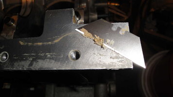
With that in mind… Tool-Wise ...I have a few extra things on order that will make my life a bit easier and some of them have already come in sooner than I thought they would. Man… You GOTTA Love the Level of Speed in Amazon’s and RockAuto’s Customer Delivery Fulfillment; they both really “deliver” BIG on that score. So now… Besides the need to take a “Fist Full of Razor Blades”...BY DRAGGING THEIR EDGES ...BACKWARDS… along all of the Finished Mating Surfaces between the Outer Engine Block where the Oil Pan-Crank-Case, Front Timing Chain Cover and Rear Engine Seal Cover Plate mate up surfaces to be cleaned off all of the Old OEM Gray ACDelco RTV residue(s)… Each and Every Bolt Hole adjacent to where that GOO was unloaded will ALSO have to be thoroughly tidied up as well.

You may ask, “Why Bother, Brother?” Well… its just this simple: Old RTV Pieces left on the Flange Surfaces and inside the tops of Bolt Holes… can suddenly rear their Ugly Heads and Pop Up and Out of those hidden spaces when New Fasteners are introduced and they can suddenly get jammed in between the components as they are being placed back onto the Engine Block. Think about how Durable, Hard and Downright ‘Rubbery’ all of that RTV Junk is, if somehow… some of it gets wedged along the flange lines of the cleaned up and ready-to-go-on covers.

These RTV pieces are as “Hard as Chinese Checkers” and will act like tiny rubber bumpers to partially keep the Flange Surfaces from cleanly mating together and sealing properly. So spending some quality time doing this careful and fastidious clean-up will pay dividends later on when you Fire it Up and “Put The Music To The Motor” and it starts to Heat Up and expand in all directions. Only the Freshest of the RTV in between those mate up points will do the trick. And just for the Hell of it… To stress this point… I’m going to place a Cardboard Box underneath the LL8 on the Engine Stand and collect ALL of that junk and show you later on just how much of the Sh*t comes off and out of the Engine Block.

Besides the use of Sharp, New Razor Blades to help with the doing of this strangely unnerving prep-work (Must NOT slice or gouge into any of the Machined Aluminum Surfaces…) your other Allies will be a decent full kit of Thread Chasers (****NOT TAPS… PLEASE… NO BOTTOMING TAPS, EITHER****) Taps are meant for CUTTING NEW METAL THREADS… NOT FOR CHASING THEM CLEAN! What you really need are Non-Destructive, Threaded Hole Chasers that have Square Facings on their Outer Threads and 45 Degree Angle Flutes cut into their circumferences to allow the Junk and Old RTV to collect inside of those spaces so that the Thread Chasers are the Threaded Equivalents of “Fuller Brushes” for sweeping up and cleaning out all of the critical threaded bolt holes inside of the engine block.

Why is this so important…? In a word… [SUBSIDENCE]. For Example… Let’s say that you are bolting two flanged pieces of metal together and on the Threaded Bolts side… you spent all afternoon with a Fine Brass Brush or say… A Wire Wheel to REALLY clean them of all the Rust, Corrosion, Old and Dessicated Red or Blue Thread-Locker and now you think that with just a Light Coating of say… Three and One Oil… they should be Right as Rain once you slip them into the Flange Holes and Tighten them and Torque them all down. So you head off in self-congratulation and say to yourself, “ I am SUCH a DAMNED Good Mechanic!” Ughhhheerrrr… Not SO Fast there, Brother Man. Because if you failed to Run a Thread Chaser and some Cutting Oil down inside of ALL of the receiving Bolt Holes several times and then Oiled and Blew them clean with Canned Air… by the time you get back from your Coffee Break.. The Torque that you applied has already begun to SUBSIDE… by squeezing down and compressing all of the Old Dirt, Rust, Corrosion, Insect Larvae, MUD Dauber Dirt from industrious Wasps, Filthy Old Grease and even some small pieces of Broken Off Threads from time to time can be left inside those Bolt Holes. So unfortunately... Your efforts to properly Torque Down those Two Flanges together would fail in the absence of doing what has been suggested above.

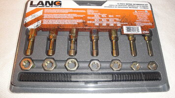
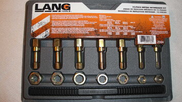
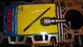
I’ll cover this topic again as we begin to put the Bottom End back inside of this Engine and discuss things in specific detail for each component and why things may be different for each set of fasteners. Here are some images of the Thread Chasers in a Kit that will ALMOST cover all of the Metric Thread Chasing needs for this LL8 Engine… But Not Quite. We still require a LONG M11X2.00MM Thread Chaser to deal with the Cylinder Head Bolt Holes in the top of the Atlas Engine Block. That Rare and Expensive Bird is a Specialty Chaser; available almost exclusively from ARP.

Cleaning up the Engine Block continues tomorrow morning:

ARPM11BY2POINT0THEADCHASER.jpgDSC01871.jpgDSC01872.jpgDSC01874.jpgDSC01884.jpgDSC01885.jpgDSC01888.jpgDSC01889.jpgDSC01890.jpgDSC01891.jpgDSC01878.jpgDSC01886.jpgDSC01892.jpgDSC05416.jpg
 
Last edited:

mrrsm

Original poster
Lifetime VIP Donor
Supporting Donor
Member
Oct 22, 2015
8,272
Tampa Bay Area
Regarding the Kent-Moore Cylinder Sleeve R&R Kit with the Kit HW images I included and set out out for display in Post #134.. Two of the other GM Sleeved Aluminum Engines listed amongst others that this Kit is also capable of performing its Magic upon besides the 4.2L Engine ...are the Ecotec 2.2L/2.4L Motors. This Video shows just the Sleeve Puller Apparatus from this very same K&M Kit in action... and thus shows just how very straight-forward the use of this Tool Kit really is; albeit without the VOP describing the necessary Preliminary Set-Up Steps for all of this equipment within this production.

This First Video is arguably The Best On Topic Video (Specific to THIS K&M Kit) for showing its use to Remove an Old Cylinder from a GM 2.4L Ecotec Engine Block:


There is lack of context in the Second Video that does not show the relationships to the Parts being used from The Full Kit of Hardware Components at play here specifically explaining the "Piece By Piece" arrangements needed for just this portion of the R&R. I really don't know WHY-TF? the Second Video VOP was in such a GD'd rush for completing this task; unless his intention was to over-emphasize just how quickly these Cylinder Removals can be done. But in any case... The Video still has demonstration value. My work with this Kit will done in such a manner as to fill in all of those other gaps in details and ensure that these procedures will be very well documented in Still Photos; including the Proper Step-By-Steps that should be explained better as I do this work on the LL8 Engine Block... From Start to Finish

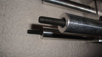
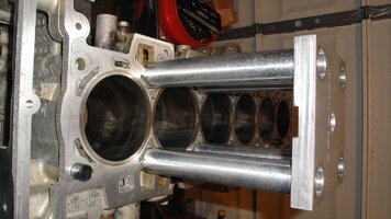
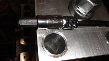
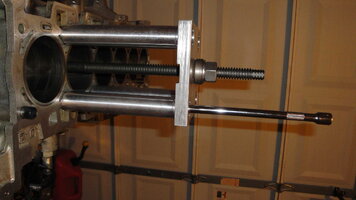
Note that the in this second, On Topic Video... The "Shiny" Four (4) Post Stand is held in place in line with the Four respective Cylinder Block Bolt Holes with either New or Used Engine Head Bolts (FelPro ES72195) that are M11X2.00MM and which are Torqued to only (11) Ft Lbs prior to installing the Threaded Arbor Screw and The "T" Base Puller that aligns with and grabs hold of the Cylinder Sleeve Rim at its Inner Engine Block Base. Then the Arbor Screw is turned Clockwise, applying a Very Significant and Uniformly Distributed amount of upward force to pull and guide the Old Cylinder Sleeve upwards and then completely out of the Engine Block. Even when using an intermediary Ball Bearing Washer and Cup Friction Reducer located just below the Hex Nut... I am not sure I understand why No High Pressure Lubrication (Molybdenum Di-Sulphide Grease) was being used on the Arbor Screw Threads which would have made its turning ever so much easier... except for the idea of NOT introducing any Foreign Substance of Lubricant or liquid oil contamination that might leak within the Aluminum Block and affect the success of the next installation phase of the New Piston Cylinder Sleeve. I'll be certain to definitely "RTFM" before I take any such actions for granted:

 
Last edited:

cornchip

Member
Jan 6, 2013
638
So these are what you would call 'dry' sleeves? No direct contact with the cooling system, just steel sleeve to aluminum bore. Never seen this done to an Atlas. Subscribed.
 

mrrsm

Original poster
Lifetime VIP Donor
Supporting Donor
Member
Oct 22, 2015
8,272
Tampa Bay Area
Absolutely… These go in... Bone Dry and get “Chuffed UP” ...Nice and Snug against the Inner-Block Aluminum Cylinder Wells… which translates to making a more even thermodynamic energy transfer from the Heat of Combustion building up in all cylinders and moving it all into Coolant Column(s) in the LL8 Water Jacket(s).

This informational link and the short video from Melling describes how they can Custom Manufacture either One… or Thousands of these Replacement Cylinder Sleeves to fit their Customers unique specs and requirements. The Materials and Manufacturing Limiting Specs they use and follow indicate that the ones I’ll be installing in my ‘04 LL8 Engine Block are equal to or exceed the GM OEM Sleeves. Keep in mind that with this Specialty Tool Kit… ALL of this work can be accomplished right there in your Garage ...with no need whatsoever for a Machine Shop to do any of this work ...and then BILL YOU FOR IT ...BIG TIME:

https://www.melling.com/product/cylinder-sleeves-performance/


This short Video describes the contrast between Wet and Dry Cylinder Sleeve Installations:


This Video shows How the Centrifugal Hot Metal Casting Techniques used by Darton Sleeves works to create useful Cast Iron replacement Cylinders:


Just some Food for Thought… If you really like your Trailblazers and Envoys that otherwise are a just a pure pleasure to own and drive... One thing to consider for anyone with “Sad, Busted LL8 Engines” sitting out in Garages under a Tarps right now because of them having been pulled and showing some Very Badly Scored Cylinder Walls and very low compression issues… Once these (6) Cylinder Sleeves get R&Rd @ $30 per Well… you could essentially wind up with a Brand, Spanking New Engine Block to work with ...and Start a Fresh Engine Build.

So ...if you have a Dormant TB or Envoy… and you possess the necessary Basic Engine Building Acumen and the requisite Mechanical Skill Set & Tools to do this job… especially for all of you Turbo-Fanatics out there… The GM 4.2L LL8 Engines that have been abandoned in Automotive Bone Yards all over the USA (and probably some up there in the Canadian Great White North as well) with Cracked or Rusting Cylinders… this idea might prompt you to check around for their availability and pricing… and if they are low enough in price to pick up on the cheap as “Grist for The LL8 Engine Re-Build Mill”… your next Engine Rebuild could get off to a very nice beginning. Now… Try doing THAT with an Old, Cracked and Busted Cast Iron Block!

Here is One Last Video 'up my sleave' ...showing the Centrifugal Cylinder Casting and Machining procedures... AND... if this one does NOT have THE COOLEST Techno-Music Theme... EVER... Then I just don't know what else to say! :>)

 
Last edited:

mrrsm

Original poster
Lifetime VIP Donor
Supporting Donor
Member
Oct 22, 2015
8,272
Tampa Bay Area
These measurements come from my small contribution to @Mooseman’s Important GM 4.2L FAQ on the GMT360 Platform:

https://gmtnation.com/forums/threads/the-gm-vortec-ll8-links-and-specs-library.16738/

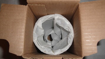
Thanks to the rapid S&H done by RockAuto.com … The One Melling Replacement Cylinder Sleeve I ordered arrived this afternoon. Afterwards, I took some “Beef Cake” Images of the partial Un-Boxing of the ‘Cosmolene’ sticky, rust-proof covered Cast Iron Sleeve. More importantly, I needed to document the Label descriptions of the specific Machining Dimensions defined as the Length, Cylinder Wall Thickness and most critically, the Inside Diameter of the Pre-Finished Cylinder Sleeve Wall(s).

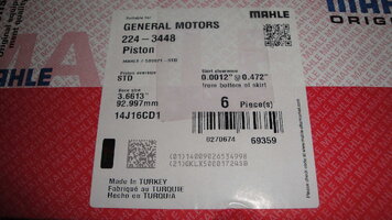
I brought out the Large Box containing the Six (6) Mahle Factory OEM Authorized GM Stock Pistons/Wrist Pins and photographed the outer Box Label for the purpose of making an immediate comparison between “The Sizes of The Buckets and Size of The Wells”. Using this information will ensure that the Pre-Finished Machined surface(s) ID of the Cylinder Sleeve(s) lend themselves to receiving a “Final Plateau Hone”. Doing this will be a must for the sake of giving this Engine a Very Long Life if the Pistons and Rings can Break In, Seal Tightly for Good Compression but also wind up being neither too tight within the Cylinder Bore(s) causing them to Overheat and Seize… Nor too loose to cause Piston Chatter, Ring Flutter and Premature Wear.

My enthusiasm grows by the minute for this idea of Replacing All (6) Atlas Engine Block Sleeves while it is still so easy to do so with the Bare Block mounted on the Engine Stand. Having Brand New Cylinders AND Brand New Pistons with OEM factory specifications instead of trying to put New Pistons into asymmetrically worn Old Cylinders solves a HUGE number of “Block Honing Old Cylinder Prep Problems” and “Engine Math” calculations.

So my primary focus right now is to grab the information about the “The Piston-To-Cylinder Gap Tolerances” and compare the numbers from BOTH of the OEM Piston vs. Cylinder Sleeve Labels. Simple Subtraction will determine how much Sleeve Honing I’ll be able to do and achieve the right Cylinder Wall Finish AND tolerant Piston Clearance(s).

Critical LL8 Engine Cylinder and Piston Specs:

Cylinder Bore Diameter - 3.6638 to 3.6644 inch
Cylinder Out Of Round - Maximum - 0.0005 inch
Cylinder Liner Recession - Maximum - 4.02 inch
Piston & Pin Piston Diameter - (1.4961 inch) down from top 3.6627-3.6633 inch
Piston to Bore Clearance- 0.0004 to 0.0017 inch

Piston to Pin Clearance- 0.00012 to 0.0005 inch
Piston Pin Bore - 0.9056 to 0.9058 inch
Piston Pin Diameter - 0.9054 to 0.9055 inch
Piston Ring - Top Groove to Ring Side Clearance- 0 0017 to 0.0037 inch
Piston Second Groove to Ring Side Clearance - 0.0017 to 0.0037 inch
Piston Oil Control Groove to Ring Side Clearance- 0.0023 to 0.0085 inch
Piston Top Ring Gap - (3.66 inch) down from top of cylinder- 0 0079 to 0.0157 inch
Piston Second Ring Gap - (3.66 inch) down from top of cylinder -0.0118 to 0.0197 inch
Piston Oil Control Ring Gap- (3.66 inch) down from top of cylinder- 0.0098 to 0.0299 inch
Compare those Numbers with the Dimensions captured in these images:

Melling Cast Iron Cylinder Sleeve:

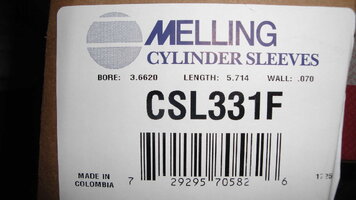
Bore Diameter: 3.6620”
Length: 5.714”
Cylinder Wall Thickness: 0.070”


Piston Diameter: 3.6613”

That leaves only 0.0007” (Seven Ten Thousandths of an Inch) of space between the Outside Diameter of the Piston and the Inside Bore Diameter… Wow… That seems kind of close… so if the Piston and Rings were to heat up enough and swell even a Tiny Bit… At 6,000 RPM… The Runaway Friction would act like a Glo-Plug and very soon… Melt the Piston & Rings into the Cylinder Wall(s); likely Seizing Up the Engine or Grenade The Pistons inside of the Cylinders. So obviously… we need to know how much more space in between them we have to free up in order to allow them to work together.

According to the Engine Specs… That Comfort Margin is:

Piston to Bore Clearance- 0.0004 to 0.0017 inch

So even though we’re just barely within the closer tolerance of 0.0004”… because the Cylinder Walls (Bore) of these Melling Cylinder Sleeves are only PARTIALLY Finished and do NOT possess the correct 45 Degree Angle of Plateau… we can use that Extra Thickness to uniformly increase the Piston to Cylinder Gap and achieve the proper Oil Holding Finish to both wear in the New Ring Sets and have a Good Seal with Good Combustion Chamber Compression as the secondary results: Neither Too Snug…Nor Too Sloppy.

Here is the Thickness of the Cylinder Sleeve Walls we have left to work with: 0.0010”

http://www.flexhoneblog.com/2009/04/what-does-plateau-hone-mean-anyway.html

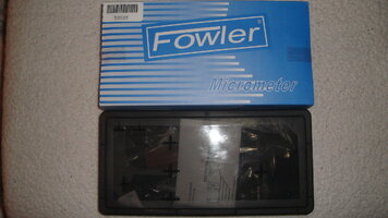
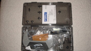
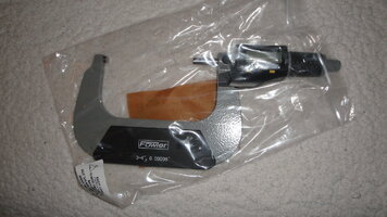
If it makes it easier for anyone not comfortable with performing the Honing Procedures that will require using either a Digital Dial Bore Gauge and/or a Snap Gauge and 4” Micrometer to Check and Double Check the Honing Progress until these exact relationships prevail… consider this as an alternative:

(1) Purchase (6) New Melling CSL331F OEM Stock Cylinder Sleeves.
(2) Purchase a Set of (6) Mahle GM OEM 224-3448 Stock Pistons/Wrist Pins/C-Clips (KIT).
(3) Purchase a Set of (6) Mahle OEM Stock Ring Sets for the GM 4.2L LL8 Engine.
(4) Locate and consult with a decent Local Machine Shop.
(5) Gather all of the necessary, critical LL8 Engine Measurements (print from the below list).
(6) Deliver ALL of the Components listed as (1) (2) (3) to the Machine Shop.
(7) Ask the Machinist to “Hone Out All (6) Cylinder Sleeves for the (6) New STOCK OEM Pistons...”.
(8) Once Finished, Thoroughly Wash & Scrub Out the (6) Cylinder Sleeve(s) with Hot, Soapy Water.
(9) Immediately Spray Down All Cylinder Sleeves with WD-40... Inside and Out.
(10) Place each Cylinder Sleeve inside of a Separate Plastic Zip Lock Bag.
(11) Before Installing New Cylinder Sleeves, Completely De-Grease them with Spray Brake Cleaner.
(12) Allow the Cylinder Sleeves & Bare Engine Block to achieve matched Ambient Air Temperature.
(14) Clean ALL K&M Tool Kit Components B4 Extracting/Installing the Old 4 New Cylinder Sleeves.
 

Attachments

  • DSC01894.jpg
    DSC01894.jpg
    221.4 KB · Views: 4
  • DSC01896.jpg
    DSC01896.jpg
    123 KB · Views: 3
  • DSC01897.jpg
    DSC01897.jpg
    132.4 KB · Views: 2
  • DSC01900.jpg
    DSC01900.jpg
    122.6 KB · Views: 2
  • DSC01901.jpg
    DSC01901.jpg
    114.2 KB · Views: 2
  • DSC01902.jpg
    DSC01902.jpg
    79 KB · Views: 2
  • DSC01906.jpg
    DSC01906.jpg
    78.9 KB · Views: 2
  • DSC01913.jpg
    DSC01913.jpg
    83 KB · Views: 2
  • DSC01916.jpg
    DSC01916.jpg
    63 KB · Views: 2
  • DSC01917.jpg
    DSC01917.jpg
    105.4 KB · Views: 2
  • DSC01919.jpg
    DSC01919.jpg
    94.6 KB · Views: 2
  • DSC01924.jpg
    DSC01924.jpg
    95.1 KB · Views: 2
  • DSC01924A.jpg
    DSC01924A.jpg
    94.5 KB · Views: 2
  • MAHLEPISTONSGM42LENGINE1.jpg
    MAHLEPISTONSGM42LENGINE1.jpg
    36.8 KB · Views: 2
  • CYLINDERWALLTHICKNESS.jpg
    CYLINDERWALLTHICKNESS.jpg
    9.9 KB · Views: 2
  • DSC01914.jpg
    DSC01914.jpg
    70.3 KB · Views: 2
  • DSC01915.jpg
    DSC01915.jpg
    73 KB · Views: 2
  • DSC01923.jpg
    DSC01923.jpg
    73.7 KB · Views: 2
  • DSC01926.jpg
    DSC01926.jpg
    98.8 KB · Views: 2
Last edited:

mrrsm

Original poster
Lifetime VIP Donor
Supporting Donor
Member
Oct 22, 2015
8,272
Tampa Bay Area
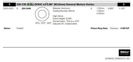
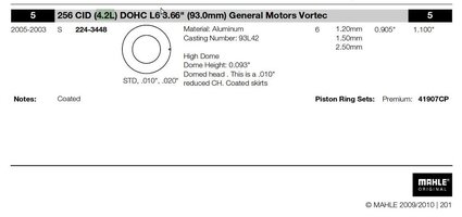
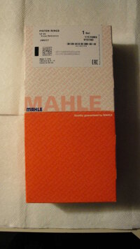
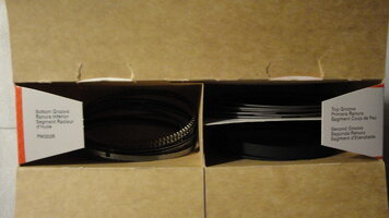
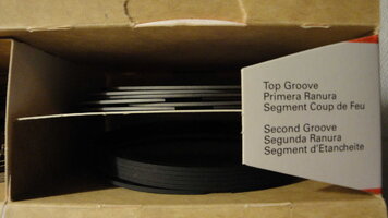
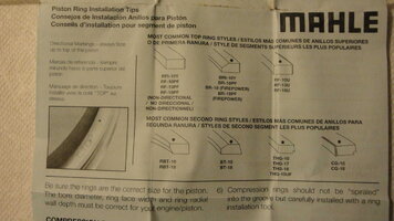
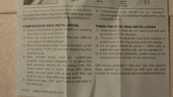
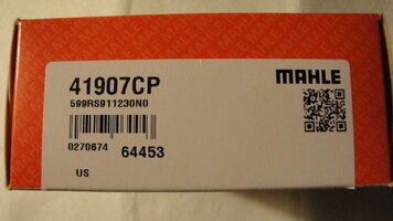
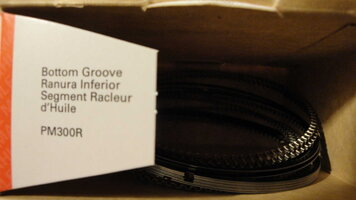
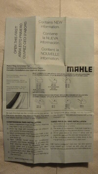
Many Moons ago… I ordered a New, Replacement Set of Rings from EngineTech Builders’ Ring Set Part # S93156-STD; which in all probability, would work just fine for this particular pending installation. But within the last week, as the Block Clean-Up work progressed… I continued my constant need to double check myself via much research… and I located another Perfect Set of MAHLE Piston Rings (CP-20 Style Kit) that are EXACTLY designed for the Mahle Piston Set Part # 224-3448 I’ll be using on this Build. The way that I did this “look-about” was to seek out “The Mahle Piston Ring Bible” and scour that catalog; Chapter and Verse to locate precisely what I was hoping to find on eBay… and for the very reasonable price of $87.00 as well… and the Ring Set just arrived.

This is the 2010 MAHLE Piston Ring Indexed Catalog that should be Downloaded and Saved in your “Mechanics’ Library”… NOT just for this project ...but for a very wide range of Makes/Models/Engines that; In the Future... may prove to be very useful information to you:

http://www.mahle-aftermarket.com/media/local-media-north-america/pdfs/pr-10-10.pdf

You may well ask… “Bobby… Why Not … Just Trust The Vendor? Of course, I could very well just go right at Sizing/Filing and Relieving all the Ring Gaps to Spec after accepting what they sent to me and go about my merry way of installing the Ring Sets onto the New Mahle Pistons… But the Problems that can Develop are THESE:

(1) In my haste to open up the Ring Sets Box… If I forgot to Look for the “Factory Seal”, I’d have No Way of Confirming that nobody has played the Trick of a ‘Bait and Switch’ between what SHOULD be Brand New, Barrel-Edged, Plasma-Moly Coated Rings… and not somebody else’s Used, Worn-Out Old Ones. Even if I looked at them all very closely… I doubt that I would be able to tell the difference! So Remember to… Check that the Box is Factory Sealed Up Tight.

(2) When the Ring Sets arrived… again, If I were being hasty… I could assiduously Measure and File down the Piston Rings per Cylinder as per Book Specs and just install them in the usual manner… But a Disaster would result if the Vendor sent me a Ring Set that WOULD be PERFECT… if the Engine on the Stand was manufactured in 2002… AND the Pistons were likewise made for that specific 2002 LL8 Motor. But in this case, the Donor Motor is Circa 2004 and the New Mahle Pistons have A Different Sized Second Compression Rings from 2003 and On. Here… Let’s have a Look at what “The Mahle Piston Ring Bible” has to say about this:

MAHLERINGBIBLE.jpg

… & Note the Lower Right Corner of THIS Mahle GM OEM Piston Set Box Label for “Piston Ring Sets” from The Mahle Piston Catalog Pages:

MAHLEPISTONSGM42LENGINE1.jpg

It is ever so important to remind yourself that Engine Building is a “Game of Numbers” in which the Laws regarding “The Limits of Tolerance”... Must NOT Be Broken! You will want to find that Perfect Balance between having all of the Mechanical Motions of the Parts inside of your Engine(s) “Roaming Comfortably” Up and Down… and In and Out… Neither being “TOO TIGHT”...Nor “TOO LOOSE”:

So… If You Wish to Become a “Lord of The Rings”… Heed this Little Bit of Advice:

“RATFLOTB!” ******Read All The F*****g Labels On The Boxes!******

In closing today's entry... The Most Complete Set of On Topic Images can more easily be reviewed ...here:

http://s557.photobucket.com/user/60...ERENGINEREPAIR/GM42LPISTONRINGS?sort=3&page=1


If You’re Nearly Correct… You’re Precisely… WRONG”

DSC01927.jpgDSC01928.jpgDSC01930.jpgDSC01931.jpgDSC01935.jpgDSC01936.jpgMAHLERINGBIBLE.jpgMAHLEPISTONSGM42LENGINE1.jpgDSC01929.jpgDSC01932.jpgDSC01933.jpgDSC01934.jpg
 
Last edited:

mrrsm

Original poster
Lifetime VIP Donor
Supporting Donor
Member
Oct 22, 2015
8,272
Tampa Bay Area
Its a Rainy, Nasty Day down here in Florida… and when this SPX Kent-Moore Kit arrived… I did not hesitate to bring it into the house ASAP because a good many of the components inside of the Kit are made of High Carbon, Tool Steel that do not need very much encouragement to Rust Right Up. For the benefit of anyone with Bare GM LL8 4.2L Engine Blocks parked on Engine Stands right now… Consider THIS:

Anyone seriously interested in performing this “Phoenix Rising From The Ashes...” sort of approach to side-stepping all of the necessities of additional cautions and care to needed to figure “How Much or How Little Honing Out Do ANY or ALL of the Aged Six Cylinders Really Require?”… Consider yourselves Lucky if you can find a Tool Kit EXACTLY like this one for somewhere between $300-$400 ...before they simply can’t be found. This IS the One Of A Kind, Complete Kit made by SPX-Kent-Moore as purpose specific to being able to Remove and Replace any or all of the GM OEM Cylinder Sleeves in the GM 4.2L Engines ...and a few others … WITHOUT THE NEED FOR A MACHINE SHOP TO DO THIS WORK… BUT YOU MUST ASSUME ALL RESPONSIBILITY FOR ANY BAD OR NEGATIVE OUTCOMES IF YOU DECIDE TO BUY AND USE THIS SPECIAL TOOL KIT!

Being able to literally bring this Engine Block back to life assumes that NO MAIN BEARINGS WERE SPUN INSIDE THE BLOCK AND CAUSING DAMAGE TO THE ENGINE. But if during the Removal of the Crankshaft, you see no evidence of Block Damage… then it will simply be a matter of your ability to Read and Follow ALL of the Set Up instructions to be found in the Spiral Instructions Notebook to the letter...One Cylinder at a time until all of the work is done.

If you wind up purchasing this Kit… You’ll find that since the Pages of the Booklet have been “Plasticized” for the sake of repetitive tool use and durability such that you won’t be able to get the Booklet to open up and lay flat on a table. So ...you won’t be able to make use of those highly reflective pages since they will have been re-shaped and re-formed to follow the contours of the under-lying tools when completely enclosed in the Carry Case. But don’t despair. To help with this problem… and for those with the actual doing of this work in mind... I removed the “Spiral Binder Screw” from the Instructional Booklet and Scanned each of the (12) + (1) Pages.

It took the use of Three Grizzly Catalogs to weigh them down enough to get all of the pages flattened out well enough to scan. If nothing else, at least this way… with these Scanned Pages, you’ll have a chance to look over ALL of the Instructions and get a better understanding of how this Tool Kit works and measure the obvious needed Skill Level you possess (or perhaps ...not) when deciding if you really want to tackle this Technical R&R in your garage and on what might be your only available Engine Block.

I’ve decided that rather than Install the New Melling Cylinder Sleeve directly into the LL8 Block FIRST and THEN Hone it out to Spec… That I’ll be Drilling out a Stack of 2”X 6” Boards to slide the Sleeve down inside and support it while I slowly Hone and Measure its upper and lower Inside Dimensions and get it ready for this Sleeve R&R. Doing it this way makes sense to me as I will have an uncommon access to the Sleeve(s), be able to examine and measure it and the New Rings for Pre-Fit and Filing while I am sitting down on my couch if needs be… and not struggling to stand over the Engine Block when it’s not really necessary.

If you are wondering whether or not it will make any difference to the ID measurement when the Sleeves have NOT as yet been pressed inside of the Engine Block… It will NOT. The New Melling Sleeve(s) have a Cylinder Wall Thickness of 0.070” (0.178 MM) and a resistance of up to 30,000 Lbs of Pressure per Square Inch inside. Ergo… The Honing Pressure will be quite minimal at best. And that reminds me… Originally, I had intended to Hone the Old (6) Cylinders out using an innocuous level of 600 Grit SC (Silicon Carbide) Flex-Hone. But with the advent of using Brand New Cylinder Sleeve(s) instead… I believe that using a 400 Grit SC level will create a much more appropriate break-in and sealing finish for the New Mahle Plasma-Coated Moly Rings and Mahle Pistons.

Here is where ALL of the related images...In Order... to this post can be found:

http://s557.photobucket.com/user/60...RENGINEREPAIR/GMKM-EN-45680-400?sort=3&page=1

EN45680800A.jpgEN45680800A5.jpgEN45680800A6.jpgEN45680800A7.jpgEN45680800A9.jpgEN45680800A10.jpgEN45680800A11.jpgEN45680800A12.jpgEN45680800A1.jpgEN45680800A2.jpgEN45680800A3.jpgEN45680800A4.jpgEN45680800A8.jpgDSC01941.jpgDSC01943.jpgDSC01944.jpgDSC01945.jpgDSC01947.jpgDSC01954.jpgDSC01955.jpg
 
Last edited:

mrrsm

Original poster
Lifetime VIP Donor
Supporting Donor
Member
Oct 22, 2015
8,272
Tampa Bay Area
I worked during the Wee Hours this morning on some “House Keeping” Block Prep and Cleanup and while the images suffice to make the obvious aspect and intent of this work as plain as my Silver Gray Hair… A few things need to be stressed about this part of the job of Block Cleaning:

(1) DO NOT RUSH! It took me somewhere around an hour to prep and clean out the (14) of the Full Set of Head Bolt Holes because THIS IS AN ALUMINUM ENGINE BLOCK AND YOU HAVE JUST ONE CHANCE NOT TO FUBAR THE DAMNED THING!

(2) I used small squirts of Foaming Spray Cutting Oil, An ARP M11X2.00MM Thread Chaser, A Can of Air, Some BLUE Paper Shop Towels and A DECENT Hand Chuck Bit Holding Tool to help with working the Thread Chaser into and out of the Engine Block.

(3) When slipping the “Business End” of the Tool down into each Bolt Hole… upon contact with the Aluminum Threads… ROTATE THE SHANK OF THE ARP TOOL COUNTER-CLOCKWISE UNTIL YOU FEEL IT “CLICK”… Then SLOWLY rotate the Tool like a #2 Pencil standing on its end; perpendicular to the Flat Surface of the Engine Head until you can feel it start to thread itself into the Hole(s). DO NOT RUSH THIS ACTION. The ARP Tool can very easily become misaligned on the way in and just as easily Wipe Out the Bolt Hole Threads… Like BUTTER!

(4) Once the ARP Tool is properly threaded into the Bolt Hole(s)… SLOWLY run the Cleaning Tip all the way down to the very bottom of the BLIND HOLES… and STOP! Then back the Shank out slowly and steady the Tool Chuck as close to the Axis of Rotation as possible so as not to Gall the Threads on the way out. Don't Lay the ARP Tool and Bit Holder on the Edges of the Engine Block to be accidentally knocked into the areas nearby.

(5) Use the Can of Air with a Red Nozzle Tube and insert it all the way down to the bottom of each Blind Head Bolt Hole and cover the upper opening around it with a BLUE Shop Towel to catch anything that gets blown out. Later on ...we will revisit this action using Spray Brake Cleaner prior to installing the Engine Head onto the Motor.

(6) After completing this Job… Use the Razor Blade to Clean up ALL Flat Engine Surfaces of any Old ACDelco Gray RTV Residue. Be Careful with the Blade(s)… Don’t Get Too Casual and Familiar while doing this work and GET CARELESS ….SLIP….AND GET CUT UP. Afterwards… Wipe down the smooth Aluminum Mating Surfaces with a Dry Red Hand Towel in order to create enough Friction to clean off any leftover rubber residue.

(7) Use the Canned Air to blow off any leftover residue rubber pieces out of the Engine Block Cavities and ensure that none of those rubbery pieces drop inside of any openings to the Oil Galleries and Water Pump and Water Jacket locations. Here are some of the images I took of the work as it progressed:

DSC01956.jpgDSC01957.jpgDSC01958.jpgDSC01959.jpgDSC01962.jpgDSC01963.jpgDSC01964.jpgDSC01965.jpgDSC01966.jpgDSC01968.jpgDSC01969.jpgDSC01974.jpgDSC01982.jpgDSC01984.jpgDSC01985.jpgDSC01990.jpgDSC01987.jpg

The Complete Image Set on this job can be viewed here:

http://s557.photobucket.com/user/60...RENGINEREPAIR/GM42LBLOCKLEANING?sort=3&page=1
 

mrrsm

Original poster
Lifetime VIP Donor
Supporting Donor
Member
Oct 22, 2015
8,272
Tampa Bay Area
With the acquisition of the K&M Cylinder Sleeve R&R Kit and having access to the COMPLETE Tool Description and Use Documentation… if you’ve perused Page #10 Sub-11 in the scanned images of these Instructions… then you understand that the parameters set forth for this particular kind of Electric Hand Drill required to drive the K&M Gear and perform the Cylinder Sleeve Flange Shaving down to within .0008” above the deck of the Aluminum Engine Block are quite Specific. The Drill Specs are defined as follows:

Electric Hand Held Drill
Capable of reaching 450-600 RPM
Triple Gear Reduction
1/2” Tool Bit Chuck
An Electric Inner Motor Capable of Handling At least (7) Amps
Possessing at least 1 1/8th Horse Power

It may not be a common problem to need to know what the Horse Power Rating of your 3/8” or 1/2” Electric Drill is… But since we really DO need to know what that rating is to prevent any falter or power failure of the chosen drill during this critical part of the job… There is a simple Mathematical Formula to use when converting Electrical Power parameters of these device into a more simplified HP number:

Let’s Convert:

First… Multiply: Amps Times Voltage to get Watts:
10 Amps X 120 Volts = 1,200 Watts

Then...Multiply: Wattage Times 0.00134 to get HP
1,200 Watts X 0.00134 = 1.608 Horse Power

So, given the need for a very robust Electric Drill having these abilities… I’ll be using THIS one:

DeWALT DWD210G 10 Amp 1/2” Pistol Grip Electric Drill

DEWALTDWD210G_.jpg

https://www.amazon.com/DEWALT-DWD210G-10-Amp-2-Inch-Pistol-Grip/dp/B001TKTI9O/ref=sr_1_fkmr0_1?ie=UTF8&qid=1523572923&sr=8-1-fkmr0&keywords=DeWALT+DWD210G+10+Amp+1/2”+Pistol+Grip+Electric+Drill

Looking ahead to the time when the Cylinder Sleeve R&R issues are completely resolved:

If you are building a Turbocharged GM LL8 4.2L, please note that the Piston Wrist Pins are NOT of the “Press Fit” Designed in the manner of requiring the Small Ends of the Connecting Rods need to heated up and have the Wrist Pins quickly inserted and aligned before cooling down. So, with freely sliding Wrist Pins… it makes perfect sense to use Howard Spiral Piston Wrist Pin Locks instead of the Common, Round Spring Wire “C” clips to fully contain and ensure that the captive Wrist Pins remain so inside of all (6) Piston Wrist Pin Bores, within the dimensions that define their limits of between - 0.9056” to 0.9058” and a Piston Pin Diameter of between - 0.9054” to 0.9055”.

This is the action I will be taking during THIS Engine Rebuild as even the Stock-As-A-Clock OEM GM LL8 Engine Build can benefit as well by replacing the “C” Clips that by design are circumferentially incomplete. In contrast, the 360 Degree containment offered by Howards Cams Spiral Lock Piston Wrist Pin Retainers Model HRC-4501 will work with Wrist Pin Diameters that range between .946” - 1.005”. They only come as a Kit of (32) Pieces and are reasonably priced and available at this link. I have a set of these on the way:

s-l1600.jpg

https://www.carid.com/howards-cams/spiral-lock-piston-wrist-pin-retainers-mpn-hrc4501.html
 
Last edited:

mrrsm

Original poster
Lifetime VIP Donor
Supporting Donor
Member
Oct 22, 2015
8,272
Tampa Bay Area
For anyone sitting back and 'rolling their gollywogs' at the idea that these "CIR-CLIPS" could not POSSIBLY ever become a problem by making any 'accidental exits' from their respective grooves in the IDs of the Piston-Pin Bore Holes... Consider the fact that only a mere fraction of their round wire bodies actually gets captured within those grooves... In fact, I'd wager it to be only 1/4 of the way inside of those grooves... and not necessarily perfectly captured inside of there, either.

Thankfully... It is a rare occurrence... but every so often we view or hear of some Poor Soul removing his Intake Manifold and trying to figure out why his engine will not start... and finding lengthy bits of stringy looking wire strewn about inside... and those things turn out to be some of the Piston Rings unwound and then went backwards and through the Intake port(s) of the Engine Head after the Intake Valve(s) broke off inside because the Piston Grenaded inside of a single Cylinder. Invariably... it's anybody's guess as to how it managed to fail. But my thinking is that THIS issue could be one more possible cause that remains unprovable after the offending Piston has been Shattered like Glass and the Motor suddenly Goes to Hell ...literally... In a Hand Basket.

It can be argued with good reason that ordinarily... nobody in their right minds would bother to completely tear down and rebuild their motors ...just for the sake of replacing the Stock Piston CIR-CLIPS on the extremely remote possibility that they might fail. But right now... if you are staring at your GM LL8 Bare Engine Block for days on end while laboring through a Complete Engine Re-Build... Replacing the Stock CIR-CLIPS on your Brand New Set of Pistons and Pins while such a Golden Opportunity presents itself ...might be a very nice addition to your Engine Rebuilding Calculus.

I took some close-up images of the GM OEM Stock Piston and Pin Bore openings (I got this set from of 2005 Trailblazer LL8 Pistons & Rods for use in the Original 2002 Motor) ...so you can get a better idea of just how precariously those clips sit in there... bearing in mind that if THESE were the Howard Cam HRC-4501 Spring-Steel Pin-Bore Locks... they'd wind up being nested DEEP INSIDE of all those Pin Bore grooves... with no "Loose Ends" sticking out as can be seen in these attached images. If you intend on Force Feeding Horse Power into yout I6 Engine and throttle the Hell out of the Motor with a Turbocharger... It would be nice not to have to worry about this ever becoming a problem ...when say... Power Shifting at 6.500 RPM:

CIRCLIP1.jpg

CIRCLIP2.jpg
CIRCLIP3.jpgCIRCLIP4.jpgCIRCLIP5.jpg
 

mrrsm

Original poster
Lifetime VIP Donor
Supporting Donor
Member
Oct 22, 2015
8,272
Tampa Bay Area
These are ALL of the (49) Images taken of Today’s work… Plus all of the previous ones covering the K&M EN-45680-400 Tool Kit:

http://s557.photobucket.com/user/60...RENGINEREPAIR/GMKM-EN-45680-400?sort=3&page=1

While getting back on the subject of conducting this “Test” of the Melling Cylinder Sleeve R&R… and remembering that I promised to faithfully record how EACH and EVERY component and sub-component of the K&M Kit operates and what they look like when in place, I had to ‘Go Backwards… To Go Forwards’ today. I decided that I would be making more unnecessary work for myself if I made the mistake of just plowing ahead with installing either One or All of these Cylinder Sleeves and THEN deciding to perform the necessity of using the Flex-Hone Tool. With the need for all of that additional Engine Prep Taping, Washing and Scrubbing them out, etc., I’m determined to design and make my own Wooden Jig and Bore Stand for this latter part and ‘Do The Dirty Work’ on these Sleeves FIRST... and then later on,press them into the Engine Block after they are absolutely ready... with no additional muss or fuss necessary.

What will this idea look like when it is built? For starters, I propose constructing a Triangular Shaped Stand made of Heavy Wood that will stop at a height of around 24” above the floor so that when I’m leaning over it with a grip on the Hand Drill and with the attached Hone… I’ll have better control of the up and down and in and out motions of the hone than I would have by trying to hone them inside of the Engine Block while the motor is mounted on the Engine Stand.

I think I can pull this design off by using several sections of 12” X 2.5” X 2 boards that have been stacked up high and then bored clean through with a DeWALT Drill Holding a 3.75” Circular Deep DeWALT Hole Saw. This will allow for making a very snug fit of the Cylinder Sleeve(s) at the top and the bottom when tucked inside of those bored out sections of wood. The Melling Cylinder Sleeves have an Outside Diameter below the Rim of almost 3.80” as measured with a 3” to 4” Micrometer… Just large enough to be ‘tight as tick on a Blue Tick Dog’… but not so large as to be a Problem to remove them from the Tri-Stand when the honing is finished.

This “Tri-Pod” Stand will be attached at the top at the margins of the three upper sides of the two wood plates using Wood Screws fastened into the 2” X 4” Studs for all Three Legs and anchored at its base on top of a 3’ Square Section of 3/4” Marine Plywood. This arrangement at the top of the stand will allow me to insert the Melling Cylinder Sleeves into the 3.75” Hole in the Center of the Stand and down through a pair of holes separated by only a few inches to stabilize and get a good grip on the OD of the sleeves.

Meanwhile, I’ll be standing firmly on the outside of the 3’ Square Plywood Platform as the means of controlling the position of the Tri-Stand that will be screwed onto it as a Base for each Leg, while I work away briefly at Honing the Cylinders out to Spec. This means that I will not have to worry about either knocking the stand over or having it move while I’m attempting to maintain a steady rate of honing strokes per minute to achieve the necessary 45 Degree Angle Cylinder Wall Finish. This Honing Work will involve a a great deal of movement using a very powerful electric hand tool and having everything properly anchored and secured means that I will be less likely to make any mistakes and get hurt while doing this task. Holding and controlling a 1.608 Horse Power Drill in your two hands… is NO Joking Matter.

The last necessity to deal with will be the need to wrap some Cardboard around the Tri-Stand as an enclosure that will run from Crown to Toe... encircling the device from the Floor of the 3’ Square Base Board and upwards to being just around 8” above the Rim of the Melling Cylinder(s). In this way… any of the ground-off inner cylinder wall metal mixed in with the Cutting or Flex-Hone Oil that will be flying out of the Bottom and Top of the Melling Cylinder where it has been fixed in the center of this Tri-Stand will be contained and prevent the problem of slinging out and spewing that stuff ‘All Over Creation” while I am doing this job.

The final bit of work I did on this Project today was to temporarily mount the K&M EN-45680-400 Tool Kit Aluminum Four Post Arbor Support onto the top of the Donor Atlas Engine Block as a ‘Dry Run’ before performing the actual removal of the #2 Cylinder OEM Sleeve and ensure that these components really DO all go together properly. To aid in the eventual hold down necessary to secure that stand to the Block, instead of using “Old Engine Head Bolts” as the K&M Kit Instructions suggest… I have BOTH sets of Brand Types of New Felpro Head Bolts ...so I opted to pick out (4) Brand New Head Bolts of the “Old Design” that I know I will NOT be using when I put on the New Engine Head and not take any chances that any of these four legs will loosen or misalign when under such tremendous Arbor Screw Threaded Rod Post Pressure that will occur when performing this Cylinder Sleeve R&R. As you’ve seen at the link above, I took some ‘set-up’ Images and I note the need for a Proper Box End Wrench for the task of either removing or installing these Cylinder Sleeves. It happens to be an unusual size of 1 1/4” in this case and is more than a match in "Mechanical Advantage" for that Arbor Press “Jesus Nut”. Now I just have to figure out how to secure the Cast Iron Rollers on the Engine Stand while I'm doing this task.

More to Follow...

DEWALTHALFINCHDRILL1.jpgDEWALTARBORPACKAGE.jpgDEWALTARBORDISCONNECT.jpgDEWALT375HOLESAW.jpgDSC02062.jpgDSC02016.jpgDSC02020.jpgDSC02021.jpgDSC02026.jpgDSC02036.jpgDSC02037.jpgDSC02041.jpgDSC02043.jpgDSC02044.jpgDSC02045.jpgDSC02046.jpgDSC02047.jpgDSC02050.jpgDSC02052.jpgDSC02055.jpg
 

mrrsm

Original poster
Lifetime VIP Donor
Supporting Donor
Member
Oct 22, 2015
8,272
Tampa Bay Area
At around 3 AM today... The Local Bad Weather announced itself upon its approach to the Gulf Coast of Florida by informing my damaged lower back with a bone deep ache that roused me from an even deeper sleep. I knew then that the plans I had prepared for the rest of this day were ruined and that I should get up and get some coffee. Soon after, I was piddling about in the garage instead of trying to rest and found some Real Treasure in the form of some pre-cut sections of 3/4" "New" Plywood; just large enough in their dimensions to aptly suit our purposes for "The Base" of the Stand. I also found some larger, thicker sections of wood around 2 1/2" X 12" x 3' that will also fit the bill for the build at hand.

Some of this stuff turned out to be 'seasoned wood' that had obviously come from a stand of Old Growth Trees that were probably harvesting Sunshine and atmospheric Carbon Dioxide for centuries perhaps or at the very least many decades, well before I was born. Such pieces of wood are of a particular interest to this part of our present job because they are quite Rock Hard and stable enough to be center drilled out to 3.75" and do the job of holding the Melling Cylinder very still and very steady while the Cylinder Hone Out process proceeds. I mention all of this with the express purpose in mind of conveying an important idea to those of you who desire to become Better Mechanics. It is quite simply this:

"Wood" You Please Keep an Open Mind about How To Solve Mechanical Problems... With Unconventional Means...?

Nobody ever loved Metals and the Mechanical Things they can become more than I have ...and still do. But just on occasion... The Use of Carpentry to solve particularly difficult problems when working with Metal Machines needs to be employed for the following important reasons:

(1) Generally speaking, Wood Materials are Always Readily Available... Metal Machines/Jigs/Tools are NOT and Cost a LOT of Money!
(2) Wood comes in all manner and kinds... some even that have many of the same characteristics of Metals. Ever hear of "Iron Wood"?
(3) Wood lends itself to being cut and purposefully re-shaped with a wide range of easily obtained Hand and Electric Tools.
(4) Wooden Things lend and yield themselves to difficult tasks that can be adjusted as needed 'on the fly...' if you learn some Basic Carpentry!
(5) If the Tools and Support pieces being made of Wood either Crack or Break... They can easily be replicated... or easily design adjusted.
(6) Wooden Tools/Parts Never Rust... and if treated, soaked or covered with the proper preservative materials, will never rot or lose their strength.
(7) In a Pinch... The Right Pieces of Wood can be a Life Saver ...one limited only by the Mechanics' Imagination and Worth their Weight in Gold.
(8) Wood is the most used, the most resilient and the most ridiculously strong Natural Building Material that has ever existed.
(9) Other than Water... Wood is the Most Important Renewable Resource on Our Planet as an "Oxygen Creator" and a "CO2... Carbon Thief".
(10) Sometimes... The only things around you that can be put purposefully to use and solve your problems ...will be made of Wood.

I always encourage anyone planning on either collecting very useful pieces of Old Wood to make a High Place in their Garages to stack and lay flat any acquired boards...and to visit your local Boat Builders Yard... especially the High End ones where large Yachts and other vessels are constructed and ask if you can have any of the Old Boxes that Ship Masts and Large Propellers and other sub-pieces under construction have been shipped in and see if the management will allow you to either carry away "The Empties" via your Truck beds ... or drag them off to one side and carefully pry, unscrew and disassemble them on site. You'll never know... unless you ask... perhaps they will let you do so. Wood is expensive no matter which Big Box Store carries what you need. Having enough on hand NOT to have to run to those places makes good sense.

Much of the "wood stores" I am using even now, after a decade or so, came from a man; a Yacht Designer... in my neighborhood who had stacks of these products and gave the entire lot to me after I did a favor for his family while he was away overseas. Some of what you see in the attached images come from that lot. When the Sun shines again... I'll continue working on the Cylinder Sleeve Jig/Stand. Please take note of the measurement I made of the top of the K&M (4) Post Aluminum Arbor Press Stand as being 5.75" Square... an important consideration if I somehow screw up manage to get any of the New Melling Sleeves accidentally 'stuck' down inside while Honing them all out when inside of this Wooden Apparatus. I will consider this need in the design of stand to let me use THAT Metal Tool to again to extricate them ...without causing any damage to the Sleeves. :>)

This is an Important Idea for All Mechanics to Understand. It comes from, "Ancient Pistol... The Machinist From Bristol"

"A Man Who Makes NO Mistakes... Makes NOTHING."

DSC02062.jpgDSC02063.jpgDSC02064.jpgDSC02065.jpgDSC02067.jpgDSC02068.jpgDSC02069.jpgDSC02070.jpgDSC02021.jpgDSC02022.jpgDSC02030.jpgDSC02057.jpg
 
Last edited:

mrrsm

Original poster
Lifetime VIP Donor
Supporting Donor
Member
Oct 22, 2015
8,272
Tampa Bay Area
Okay… I worked quite a bit on the Lumber and Doped out the measurements/cutting of the Three 2 ½ X 12” “Plates” that I also drilled within one inch of all four corners with a 1/2” Carpenter’s Spade Wood Bit to accommodate (4) M10 X 1.50 X 140 MM Galvanized Bolts, with (4) Matching Nuts and their S/S Washers to Bolt Up and Hold All Three Plates Together. I took the cross-corner “X” Measurements and using the New DeWALT 3.75” Hole Saw and 7/16” Arbor Bit and using the Heavy Duty DeWALT 1/2” Hand Drill, I carefully drilled through the center of all three boards.

I note that I made these holes slightly asymmetric on purpose; just in case the Melling Sleeve(s) wind up becoming too loose when being passed into the center of all three boards and ostensibly held snugly therein. This arrangement allows me to make tighter adjustments if needs be to cinch the three boards up against the (OD) outside diameter of the Melling Cylinder Sleeve and keep it from either spinning around… or lifting up and out and/or back down again during these same Honing Motions.

I would urge anyone attempting this work with similar equipment to respect it’s Torque and Power and not get injured by forgetting to SECURELY CLAMP, HOLD OR TIE DOWN THE WORK PIECE(S). This Drill is Powerful enough to snap your lower arm off at the wrist or destroy your shoulder if you make the mistake of letting it get away from you!

LISTEN TO ME… THIS IS A DANGEROUS TOOL…IT IS NOT A TOY! Be extremely aware of what you are doing! UNPLUG the DeWALT Drill from the Extension Cord EACH AND EVERY TIME YOU CHANGE ANY DRILLS AND/OR ARBOR BITS/HOLE SAWS! If it Accidentally Spins Out of Control and it gets away from you and the Cord Winds around and it Pins your “Trigger Finger” to the Trigger… You will NOT be able to STOP the Damage it WILL Do to YOU Before You Can Shut It OFF! So... Be Very Respectful and Cautious with this Device.

Tomorrow… I’ll start work on the (4) (Nope... NOT Three) 24” Legs and the 3/4” Plywood Platform and also try to insert the sleeve as well...hopefully without cracking the Wood Enclosure and make any internal adjustments needed to this Wooden Tool. More to Follow:

ALL of the images relating to today’s work are located at this link:

http://s557.photobucket.com/user/60...RENGINEREPAIR/GMKM-EN-45680-400?sort=3&page=1

DSC02075.jpgDSC02088.jpgDSC02089.jpgDSC02082.jpgDSC02092.JPGDSC02099.jpgDSC02098.jpgDSC02097.jpgDSC02100.jpgDSC02096.jpgDSC02104.jpgDSC02103.jpg
 

mrrsm

Original poster
Lifetime VIP Donor
Supporting Donor
Member
Oct 22, 2015
8,272
Tampa Bay Area
Even with getting a bit of a late start on the Day… I managed to get back out into the Garage and finish the Wooden Melling Cylinder Hone Stand. I needed to either adjust some Dimensions or change my Build Tactics in order to get this this completed in what I would consider to be “Record Time”...at least for me it seemed so, anyway. Here is what this work entailed:

(1) Instead of using (4) Leg Supports of 24” as originally planned… I shortened that height to 16” above the Plywood Base due to the sheer size (length, actually) of the DeWALT 1/2” Electric Drill AND The Flex-Hone. Otherwise I would have to withdraw the Flex-Hone Cylinder Hone almost up into my armpit when standing straight up and throw my Honing motions quite off balance as a result.

(2) I made Fresh End Cuts and Squared up all (4) 2” X 4” Legs to measure exactly 16” in Length.

(3) I laid out the “Melling Cylinder Hone Box” portion of the Stand on the deck of the Plywood Base and positioned and Magic Marker outlined this “Bulky Chunk” of Wood with it moved as far towards the rear edge of the rectangular plywood base as possible. This placement will give me more “Standing Room” on top of the Platform when Honing.

(4) I placed all (4) Four 2” X 4” X 16” Legs equidistant in a center crossing pattern rather than by moving the support legs to the squared off edges of the “Bulky Chunk” to allow for the need to Drill and Screw the (4) Legs into the sides of the “Cylinder Hone Box” and NOT Drill and Screw into the M10 Bolts holding the Three Plates together. It is important to be able to use small chunks of Scrap Wood and some Wood Screw Handle Clamps creatively enough to place the Legs in the proper position and hold them still enough with the blocks of wood placed at Right Angles to each other in order act to Brace each Leg to finalize screwing in the Two Screws Per Leg and not FUBAR their attachment points to the Plywood Base.

(5) I pre-drilled out all of the 2” X 4” X 16” Legs at the Top for 3 1/2” Carbon Steel Deck Screws and then placed all of the Fasteners into their pre-drill points along with a swipe of Candle Wax on their Thread Lines to lubricate and prevent any of the Old Wood pieces from Cracking and Splitting when under so much counter-tension.

(6) Prior to finalizing these Screw In Points, I use a Small Plastic Mallet to Tap the “Bulky Chunk” into a Flat and Level position… Dead Even with the tops of each of the (4) Legs. Afterwards… I set the Finished Device on the Deck and confirmed that I would have enough “Standing Room” to work with the Drill and Hone.

(7) Even with many careful measurements… Due to the Age of the Wood Pieces, I found there was a lack of what could be considered ‘Absolute Perfection’ with the mating up of these wooden component alignments. However, when I was finished, the Device proved to be Very Sturdy and Level and I have every confidence that the New Melling Gray Cast Iron Cylinder will fit inside and hold properly… and that the final, Finishing Plateau Hone be completed without any problems.

(8) Taking a Leaf out of Lord Kelvin’s Book on Temperature Differentials… I will leave the Wooden Melling Honing Stand sitting outside in my Hot Garage to Expand … and then place the New Melling Cylinder into a Zip-Lock Bag with a moisture absorbent Silica Gel Packet inside and thence place it into my Freezer to Chill Down and Contract the Cylinder prior to quickly placing the two items together and tapping on the Cylinder Flange to drive it into the Drilled Out Melling Honing Stand with a Plastic Mallet. Then I’ll allow them both to come back to Room Temperature and see how snugly they fit together prior to attempting to Hone Out the New Cylinder.

I am still awaiting the arrival of some Specialty Precision Measuring Tools that I’ll need to employ prior to any Hone Work. I am ever suspicious of anyone else’s interpretations of the alleged Precision Measurements of these Engine Parts and unless I have done this job myself… I will not be satisfied. If everything comes out within the proper specifications… Then ...Let The Honing Begin!

http://s557.photobucket.com/user/60...RENGINEREPAIR/GMKM-EN-45680-400?sort=3&page=1

DSC02106.jpgDSC02108.jpgDSC02109.jpgDSC02111.jpgDSC02112.jpgDSC02113.jpgDSC02114.jpgDSC02115.jpgDSC02119.jpgDSC02121.jpgDSC02123.jpgDSC02125.jpgDSC02126.jpgDSC02127.jpgDSC02128.jpgDSC02129.jpgDSC02130.jpgDSC02132.jpgDSC02135.jpgDSC02136.jpg
 
Last edited:

mrrsm

Original poster
Lifetime VIP Donor
Supporting Donor
Member
Oct 22, 2015
8,272
Tampa Bay Area
With the arrival of my Fowler 3”- 4” OD Micrometer… Its time to get down to the REAL Nitty Gritty of Engine Building: Precision Measurement. If you are intending on re-building Motors that conform to the proper specifications laid out for the particular engine components being used at the very heart of your work… you MUST know what the relationships are between those parts and pieces… and if you are intent on re-using certain major components out of the original engine(s) than this is particularly true. There is no place for “Eye-Balling” or using “The Rule of Thumb” in these circumstances!

“If You're Nearly Correct...You’re Precisely… Wrong.”

In our situation… we have an engine that was operated since 2004 and attained the mileage of around 160,000 Miles just before this Complete Engine Tear Down. And while I do not need to know absolutely every variation that happened deep inside of this Motor after the SUV drove off the Factory Line… there are some particular changes that may have happened since then that I will need to understand. Those come under the heading of “Measured Tolerances” that must be explored and confirmed . The acceptance or rejection of any of these components will initially depend upon what can be seen with the Naked Eye...but the reliable understanding will come from very precise measurements of the outside and inside dimensions as the final arbiter of what stays ...or what goes in the Trash instead of going inside of this Re-Built Motor.

The Primary Precision Measuring Tools employed here include digital Depth Gauges, Snap Gauges, Dial Bore Gauges and last but not least Inside and Outside Micrometers. Unfortunately… there are wide ranges of accuracy and reliability that have consummate increases in the cost of these tools… but for our purposes… finding our measurements to be as close as a few ten thousandths of an inch will suffice. The only question after that is whether a balance between performance and the Bang for The Buck can be achieved… and whether you wish to become or remain a “Micrometer Measurement Purist” by insisting on reading the results off of the Barrels; with their arcane ‘Nth Degree’ Incremental Scales to figure things out… or bump up to the performance offered by using an Electronic Digital version… and read the results accurately and rapidly. This is what the original manual device looks like and how it is read when in use:

https://en.wikipedia.org/wiki/Micrometer#/media/File:Micrometer_no_zero_error.gif

For the sake of moving things along… I’ve chosen an American Company called F. V. Fowler whose product lines, quality of equipment and reasonable pricing meets all of my requirements to a Capital “T”. This link and video should give you a better idea about their operations up in Massachusetts for deciding to make the Amazon purchase of their Electronic Digital Micrometer:

www.fvfowler.com


The Micrometer Kit arrived earlier this afternoon and I have memorialized the Un-Boxing of this device and supporting equipment in the attached images. Amazon carries this same item On Sale here:

https://www.amazon.com/dp/B01L8Q8CFE/?tag=gmtnation-20

The next task at hand is to measure the Inside Diameter of the New Melling Cast Iron Cylinder Sleeve and compare those results with information posted on the OEM Product Boxes… as well as measuring the Outside Diameter(s) of each piston at their proscribed measuring position slightly under 1.5” above the Bottom of the Piston Skirts; 90 Degrees to the Wrist Pin Bore. All of these measurements will have to be compared to what the OEM Manual describes as acceptable tolerances for them all and figure out how much leeway I have within the spaces inside of the Cylinder Sleeve to Hone Down to the right comfort zone between the fit of the Pistons and Cylinder Bore.

In cases where inside Bore measurements can be done using a Dial Bore Gauge… the reality is that ordinarily, a DBG does not really “measure“ anything… it simply gets set up to compare the differences between two arbitrary numbers. So like it or not… the use of “T” Snap Gauges to establish measurement of the ID's of each cylinder must be taken first ...and then the “T” Snap Gauges require the use of a sensitive OD Micrometer to identify its findings …multiple times… at multiple places (depths) inside of each cylinder … and always taken at 90 Degrees to each other.

This work is very dependent upon having the Micrometer being gently mounted in the inverted position inside of a Small Bench Vise using a soft cloth to protect the outer frame of the device; neither squeezed too tight to damage the tool, nor alter the output of its results. This leaves the Mechanics’ hands free to manipulate the two ends of the previously spring compressed rounded ends of the legs with their positions locked in place after tightening down the very tip end of the “T” Handle...and accurately measure its length each time.

After that… the first comparison of the ID Measurements inside of each Cylinder Sleeve must be made against the Minimum and Maximum allowable dimensions specified by the GM Shop Manual. If they are acceptable… then perhaps the use of a simple 400 Grit Flex-Hone Out to re-establish a fresh cylinder surface having those 45 Degree Oil Trapping "Hash" Lines will be sufficient with using New Stock Pistons and Stock Rings to solve the TOP END problems of Excessive Wear, Compression, Power Loss and Worn Rings.

If not… Either a 0.010” (0.025 MM) 0.020” (0.050 MM) re-boring of the Engine Block Cylinder Sleeves will be necessary with the same increase in the sizing for the Pistons and Rings to Match. Or failing that solution… Simply replace the Bad Cylinders entirely with Brand New Ones as is being attempted here and avoid worrying about “Piston Slap” that will certainly NOT be remedied by removing more metal during the honing out process. I am going to Begin at the Beginning by examining the New Melling Sleeve first and see what it has to tell us ...before mounting it inside of the Wooden Melling Hone Stand and performing the 400 Grit Flex-Hone w/Honing Oil procedure.

More to Follow...

http://s557.photobucket.com/user/60dgrzbelow0/library/MICROMETER?sort=2&page=1


DSC02139.jpgDSC02145.jpgDSC02146.jpgDSC02147.jpgDSC02148.jpgDSC02150.jpgDSC02152.jpgDSC02154.jpgDSC02155.jpgDSC02157.jpgDSC02158.jpgDSC02159.jpgDSC02160.jpgDSC02163.jpgDSC02164.jpgDSC02165.jpgDSC02169.jpgDSC02172.jpgDSC02170.jpgDSC02171.jpg
 
Last edited:

mrrsm

Original poster
Lifetime VIP Donor
Supporting Donor
Member
Oct 22, 2015
8,272
Tampa Bay Area
The choice you make of How to Document your Component Dimensions is entirely up to you… but since there will be a great deal of information coming out of all of these measurements that needs doing… it would be nice if you establish your methodology early in the process to track and record each and every step… and stick to it. In the happy afterglow of your Final Assembly… besides having checked and double checked your work on each and every component as piece by piece… they all go inside of the Engine along with their unique subset of components associated with each one… THE VERY LAST THING you want creeping into your sub-conscious during the Engine Building Procedures… is .... Self-Doubt.

We can all see the way to avoid this awful sensation by following the Best Example via Paul’s Model of Action in his videos as @littleblazer when he went about cleaning off the surfaces of every single Critical Fastener with Brake Cleaner and then daubed on a little Permanent Paint from a Paint Pen on their tops. He did this after double checking that each and every one was Torqued Down to a Fair-Thee-Well. But without that “Paint Pen Dot of Confirmation” he might have wondered later on… “Did I Tighten Down ALL of the Main Caps and Finish them with the Proper Torque… Or NOT?”

Even if you have no intention of ever re-building your own LL8 Engine… Visit Brian and Paul’s “Red Truck Resurrection” to Watch… to Learn… and to Realize that Good Mechanics are Always Careful… Always Thoughtful… and … Always Follow a Decent Engine Assembly Build Plan. Have a look at the PDF attached via this Link:

https://dalejr.powernationtv.com/assets/powernationtv/pdf/engine-data-sheet.pdf

...and this one is available as an Example .XLS Spreadsheet from here:

https://www.thesamba.com/vw/archives/info/engine_build_sheet.php

For the sake of @Capote's eventual Turbo Build... Much of what I have mentioned above is echoed in this video done by Eric The Car Guy's personal Engine Builder ...who mentions the need to have more relaxed clearances in Turbo Applications. Please overlook the fact that Eric's Turbo Build here happens to be on a Ford V8 with its own special assembly considerations ... Its the Principles of Proper Engine Assembly that we are concerned with here:

 
Last edited:
  • Like
Reactions: brianlibby791

littleblazer

Member
Jul 6, 2014
9,267
The choice you make of How to Document your Component Dimensions is entirely up to you… but since there will be a great deal of information coming out of all of these measurements that needs doing… it would be nice if you establish your methodology early in the process to track and record each and every step… and stick to it. In the happy afterglow of your Final Assembly… besides having checked and double checked your work on each and every component as piece by piece… they all go inside of the Engine along with their unique subset of components associated with each one… THE VERY LAST THING you want creeping into your sub-conscious during the Engine Building Procedures… is .... Self-Doubt.

We can all see the way to avoid this awful sensation by following the Best Example via Paul’s Model of Action in his videos as @littleblazer when he went about cleaning off the surfaces of every single Critical Fastener with Brake Cleaner and then daubed on a little Permanent Paint from a Paint Pen on their tops. He did this after double checking that each and every one was Torqued Down to a Fair-Thee-Well. But without that “Paint Pen Dot of Confirmation” he might have wondered later on… “Did I Tighten Down ALL of the Main Caps and Finish them with the Proper Torque…?”

Even if you have no intention of ever re-building your own LL8 Engine… Visit Brian and Paul’s “Red Truck Resurrection” to Watch… to Learn… and to Realize that Good Mechanics are Always Careful… Always Thoughtful… and … Always Follow a Decent Engine Assembly Build Plan. Have a look at the PDF attached via this Link:

https://dalejr.powernationtv.com/assets/powernationtv/pdf/engine-data-sheet.pdf

...and this one is available as an Example .XLS Spreadsheet from here:

https://www.thesamba.com/vw/archives/info/engine_build_sheet.php
Lol at calling me a good mechanic.:crackup:Nah but seriously, that was my OCD... I had to make sure. I re-checked the torque probably 10 times after I put on that mark too.

 

mrrsm

Original poster
Lifetime VIP Donor
Supporting Donor
Member
Oct 22, 2015
8,272
Tampa Bay Area
After spending the last six weeks suffering from heat exhaustion both inside the house due to an HVAC Failure and outside due to it just being Florida in the Summer... I finally have had the work done at great expense (but with wonderful results) of replacing of the Old R-22 HVAC System over to a Trane XR-15 4 Ton R-410A system. This transition has presented me with Great Comfort and Cool... but also created a new situation of having to schedule a slot for this coming Wednesday, as a County Inspector will be arriving to examine the good work the HVAC Guys from Advanced Cooling Systems, Inc. performed on this installation. I am still trying to work out the best way to replace the broken Garage Attic folding ceiling stairwell with the Werner All Aluminum (375) Lb flavor I had to purchase from Home Depot as the last bit of work needed to allow the Inspector to safely climb up into the Attic and look things over ...without getting hurt.

Now this might seem like a lame excuse for my not getting “off my Hiatus” and back on the ”Engine Re-Build Horse”… but my Garage has been in perpetual disarray and the Back Yard has been looking like an easy qualifier for cleanup via the EPA Super-Fund for Project Parts and Pieces(… but nothing Toxic in the way of Chemical or Oil spills, mind you). So I've had to do an enormous amount of ...shall we say… “Tidying Up” of both of these locations this month and prove that all the money I spent last year on building a 10’ X 14’ elevated Arrow Shed really was worth all that expense. I must say… it is INCREDIBLE how really roomy it is inside and how much “stuff” I have been able to heft up and transpose from both the cluttered Garage areas and from around the Back Yard into it... with room to spare. So… So far… So good.

In any case… If I can get through the scrutiny of this Wednesday In-Door - Out-Door Inspection without getting “gigged” or fined for any these issues… then I’ll be able to get back to working on pulling the first of six Engine Block Sleeves and installing and fitting the New Melling one after honing it out properly on my Hand Made Wood Cylinder Holding apparatus. I suppose that having a "Tidy" Garage will certainly NOT hurt by improving the working conditions surrounding this on-going LL8 Re-Build... but I cannot swear that it will remain so for very long.

That said… I also wanted to make mention of a Tool that follows the Engine Re-Building theme all the way through Eric The Car Guy’s Video in Post # 151 above… and that is... The Speed Wrench. THIS is one of those Tools that really deserves to be in Everyone’s Tool Box for the agonizing jobs that require the “4 Rs” of the Rapid, Repetitive Removal and Re-installation of many groups of Fasteners.

The amount of time and aggravation you can save using one of these makes the cost of them quite nominal and well worth the getting. There are quite a few variations in 3/8” and 1/2” flavors available on Amazon… but Craftsman has one in 3/8” that looks to be the twin of the one Eric’s Engine Builder is demonstrating to very great effect starting at around 23:48 of that video. So if you want one… Here is where to find it:

https://www.amazon.com/dp/B00065T0NC/?tag=gmtnation-20

More to Follow Later This Week…


All Solutions… Breed New Problems...”
 
Last edited:

mrrsm

Original poster
Lifetime VIP Donor
Supporting Donor
Member
Oct 22, 2015
8,272
Tampa Bay Area
Recently… I received a PM from @Locksmith alerting me that during the viewing of a Youtube video lately produced by @MAY03LT he was watching on the subject of measuring Oil Pressure properly using an Analog Method ...that Drew also took the time to draw the attention of his Viewers over here to GMT Nation. At around 5:00 into the Video… He was nice enough to stress that he gives credit back to where credit seems due.. .and mentioned yours truly and GMTN as good sources of information regarding Rebuilding the GM Atlas 4.2L. Since presently he is apparently right in the middle of his OWN 200,000 Mile Complete Engine Overhaul, I suspect that it may have helped him, as well.

I’d like to thank Drew here for making this Honorable Mention and add that at some point… even with the dwindling number of vehicles that have basically “High Mileaged” their I-6 Powered SUVs into possible near extinction ...that there remains great hope for those who will seek out Members like @m.mcmillen (The Legendary Mac) for his guidance and experience in overhauling their own engines… thereby resurrecting this fine group of Six Cylinder GMT360 Vehicles:


“Praise From Caesar… Is Praise, Indeed...”
 

mrrsm

Original poster
Lifetime VIP Donor
Supporting Donor
Member
Oct 22, 2015
8,272
Tampa Bay Area
At the prior, friendly urging of @Capote regarding the creation of my MRRSM Youtube Channel and documenting the stages of the Complete Rebuild, I’ve decided to first obtain a fairly decent Budget Video Camera with ancillary equipment to make better quality videos from the jump. As I work through the various filming sessions… I’ll take the proper care during the setup of everything to cover discreet aspects of the components, their purpose and appearance, their specs and the means for measurement, special handling issues, the block preparation, the lubrication, the tools, and the techniques involved in doing all of these things in their proper order.

As things get done and memorialized as sub-set Youtube Videos, I’ll post the links and any particular additional data back here. I’m not going try to cover and include everything about the entire build all at once in Huge Chunks, as this project involves one, ‘Six Cylinder Elephant’ that deserves to be served up on a Mechanic’s Buffet Table for a sort of “One Bite At A Time” style of learning consumption. One last thought… I’m not particularly interested in observing any criticism about my choice of the Camera and the Gear being used here. This purchase is strictly a less expensive, but necessary means to a practical end to memorialize everything about Rebuilding the GM LL8 as much as possible. So if anyone is so inclined as to opine on the subject of Video-graphy and how much BETTER their Camera Gear is…blah...blah...blah… By all means… Please… Spend your Own Money and create-write your Own Thread on this particular topic ...and you can make your condemnations and complaints over there.


CANONELPH360HS.jpg

Here is an Un-Boxing and Performance Review from an apparently informed and youthful camera enthusiast:


And another Camera Geek's Review:

 
Last edited:

mrrsm

Original poster
Lifetime VIP Donor
Supporting Donor
Member
Oct 22, 2015
8,272
Tampa Bay Area
Okay… even without having added much in the way of updates on this Engine Rebuild Thread ...which by now... deserves to have a A Grey Beard to rival that of Rumpelstiltskin’s… I have been working on the Upper Block (inverted on the Engine Stand) in Dibs and Dabs. Of late… the topic of using Helicoils to repair the Primary Engine Fasteners in the GM Atlas LL8 4.2L Engine came up and this prompted my counter-response concerning the arguably better “How to Use the TIME-SERT Thread Repair System” over on another contemporary Thread Posting. Of course that prompted me to dig in even deeper about what it would take to Completely Upgrade the Upper Engine Block Crankshaft Mains Threaded Holes inside the Aluminum Engine Block with (14) M10X1.50X24MM Serts. The logical Question this may evoke in the minds of many is: “Why Would You Want To Do That?” The reasons ...when taken in total ...will make perfect sense:

(1) The use of Torque To Yield Fasteners on Primary Components like Main Bolt Holes and Head-To-Block Bolt Holes is not only destructive to the Original Boltsit also Damages, Distorts and can Destroy the Metric Thread Lines inside of the Aluminum Engine Block as well.

(2) If you examine the Thread Lines of the Removed/Extracted Bolts…. You will observe a “Silvery” appearance to them… THAT substance is the Pulverized Aluminum that has been Wiped off of each and every Thread Line deep inside of the Engine Block during their Installation AND Removal.

(3) This can be tested and proven by simply inserting a Brand New Main Cap Screw (Bolt) or Engine Head Cap Screw (Bolt) into any of those holes… and screw them down into the block with your bare fingers. You will find that they not only easily thread all the way down ...they will also feel LOOSE and will even rattle inside on the way in when doing so.

(4) This implies a LOSS OF ALUMINUM MASS in the Inside Diameter of the Bolt Holes’ Structure that can threaten that New Fasteners can Slip, Gall and Strip Out Bolt Threads with ease since their Original Male to Female Thread Line have been so altered and damaged as to allow this to occur.

(5) When performed with care…. Using THE TIME-SERT Threaded Hole Repair System employs Metric, Threaded Steel Cylinders (NOT a Wound Wire Design) that offers a superior “Steel on Steel” thread line interface between the Bolts and the Aluminum Engine Block that are not only Permanent...but STRONGER as well.

It is well known that these prohibitively expensive TIME-SERT KITS are mostly meant for use by Trained GM ASE Mechanics and Machine Shop Technicians rather than for the General Consumption by ‘Shade Tree Mechanics’ such as yours truly… but having already used this System first hand on my 2002 In-Dwelling Engine Block to repair a FUBARed Broken Head Bolt right at the #1 Cylinder… success is its own reward and I feel confident that there is no place on this Engine that the Proper TIME-SERT Kit cannot be used after breaking the ice and permanently fixing what I thought would actually doom that motor...on my own steam.

That state of mind lead me to investigate the cost of the complete TS System for this and other repairs and it surprised even me when it was averaging around $1,500.00 for the entire set up. Now strangely enough… I found that throughout these search efforts…. TWO variants of the TIME-SERT KITS kept coming up:

(1) TIME-SERT (With TWO Sub-Kits to comprise the entire required Set)
(2) Kent-Moore (With THREE Sub-Kits to comprise the entire required Set)

https://www.flickr.com/photos/126111508@N07/albums/72157701032583401

Naturally… the clever approach to the problem of being able to lay your hands upon these is to count on the fact that there will always be some Poor Soul in a Shop somewhere that mislaid a portion of the myriad parts and pieces of these Kits and be inclined to SELL THEM ON eBay for much reduced prices. And… That is exactly how I managed to find the Two of the Three Part Set I needed in order to be able to Drill Out, Re-Thread and Install those (14) Mains M10X1.50MMX24MM Steel In-SERTS.

I had to peek and poke around quite a bit and ZOOM in on the available Incomplete Offers in order to confirm that I would be getting ALL of the Major Tools that will be indispensable if completing this Technical Task. When I managed to locate them… I actually found some with imagery showing that these High Grade, High Quality Carbon Steel Tools that were Rusted Up very badly ...were being offered for three times the price of another identical K&M Sub-Kit that were PERFECT and Brand NEW (individually Plastic Wrapped) as far as having all the required Metric Sizes I needed for the job included. I managed to purchase Parts (2) and (3) of the K&M (1-3) Main Kit for around $70.00 per Sub-Kit...and when they arrived… I was NOT disappointed to discover that everything I would need was included in their K&M Gray Metal Rectangular Carry Cases. Here isa Link to my “Flickr-Bucket” that shows what all the fuss is about:

https://www.flickr.com/photos/126111508@N07/albums/72157675220328698

The next piece of this puzzle deserves your undivided attention because I have yet to solve this “sticky” problem and anyone with any tendency to BREAK COMPONENTS DURING R&R WORK… should shy away of even thinking about doing this Task. What concerns me right is how recalcitrant those (14) Hollow Main Cap Alignment Dowel Pins remain that are so firmly seated inside the oversize Outer, Upper Block Main Bolt Holes. I have approached their removal with two different types of Specialty Tools... and neither of the two have managed to budge those Hollow Pins one scintilla.

So... I’m still working on figuring out a Proper, Non-Destructive Method that may prompt me to use a Propane Torch to gently heat the Block Buttresses and expand them enough to work those Dowels free from their ‘Tunnels’ and not damage or crack the surrounding Aluminum supporting metal in the process. This job is entirely dependent upon knowing the following Critical Measurements in order to set up THE TIME-SERT DRILL DEPTH, THE COUNTER-SINK OD and THE SERT INSTALLATION TOOL ...which I CANNOT determine while the Dowel Pins remain In-Dwelling:

(1) What is the Outer Diameter of the Dowel Pins?
(2) What is the Inner Diameter of the Dowel Pins?
(3) What is the Inner Diameter of the Holes at the Buttress Top ...once the Dowels are removed?
(4) What is the Depth of the Holes from the Buttress Top to the Block to the Dowel Seating Depth?
(5) What is the Entire Depth of the Bolt Hole from the Buttress Top to the Bottom of the Blind Hole?
(6) What is the Total Depth of the Thread Line from just below the Dowel Contact level inside of the Upper Bolt hole to the End of the Thread Line at the Bottom of the Blind Hole?


As you can see… there are many measurement considerations that MUST be attended to even before you open up those Gray Boxes and start grabbing out Tools… or you’ll risk a complete failure of this repair. So if you are ill-inclined to being mindful and fastidious to these critical details…. For the sake of not “lunching” your Engine Block… Skip this idea altogether and move on to doing the job of just cleaning out those Mains Bolt Holes and then lightly Oiling the Threads (VERY Lightly!) of those M10X1.50X150MM (14) Main Cap and Cradle Bolts and Assemble-Tighten-Torque-&-TTY everything after you... RTFM.

Postscript.

It is easy to throw around expressions like..."Just Put a Helicoil in there..." for Threaded Insert Bolt Hole Repair Kits without actually having enough real supporting data and “Broken Component versus Required Tool Kit” information to provide accurate measurements and explain which of these kits is appropriate for each unique situation. However…. In order to get thoroughly grounded on this topic… This PDF from TIME-SERT is very comprehensive and very instructional for anyone considering using this unique system to permanently repair damaged Bolt Holes in Engine Blocks:

https://timesert.com/html/catalog.pdf

… and here is a Link to the TIME-SERT FAQ for the other major questions involved:

https://www.timesert.com/html/faq.html#24

https://www.time-sert.com/metric-kits/

https://forums.trailvoy.com/archive/index.php/t-65809.html
 
Last edited:

mrrsm

Original poster
Lifetime VIP Donor
Supporting Donor
Member
Oct 22, 2015
8,272
Tampa Bay Area
Okay…. I think I may have figured out a practical way to make a “Solid” Dowel Pin Extraction Tool: The CAL-VAN 95300 Metric Dowel Pin Puller… work on the HOLLOW Steel Cylinder Dowels fitted both in the Upper Aluminum Engine Block ... with a few also being used as Guides in the Top of the Engine for aligning the Engine Head onto the GM LL8 4.2L Block:

Available from Amazon via THIS Link:

https://www.amazon.com/dp/B0066PI4EW/?tag=gmtnation-20

Here is an Excellent Video on “How-To-Use” this Tool:


Last month… I had to come up with a solution that would solve the problem of causing any damage to those Hollow Dowel Pins OR to the engine Block in the process by keeping them from collapsing and getting permanently ruined during this removal chore. I searched High and Low for the right size Steel Pin or Plug hqving the Right OD so that it would fit very snugly inside of the Hollow Dowels. The idea was to offer 360 Degrees of solid interior support that so that no matter how much external pressure gets applied via any Dowel Puller tightened up around the Outside Diameter… the Thin-Wall Hollow Dowels would not collapse inside of the Mains Bolt Holes. I rifled every tool box trying to find the appropriate candidate for this job… but 'No Love and No Luck'. Nada.

Finally, I located an odd Packet of Four (4) 10.9 (Grade 8) Super High Quality Blued Fine Thread Bolts that were slightly larger than 10MM in their OD...and Voila’ ...after cutting off the threaded end with a 4.5” Diamond Edged Saw Blade and using a Bastard File to Radius the edge of the Bolt… I found that it was a fairly snug fit inside of the hollow portions of the Dowels.

If you examine the below image… you can see it being used right along with section of “Pink” Thick-Walled Copper Plumbing Pipe that I chopped a large enough section out of lengthwise to allow the Copper material to Squeeze Down around the Hollow Steel Dowel Pin and attempt its removal with a regular pair of Vice Grips as the Clamping-Turning Force. This idea failed due to how determined these Damned Dowels are at remaining ‘steadfast in their duty’:

46028859622_ba5df0dbbd_z.jpg45354474164_1dcbc5ba1e_z.jpg46028859452_da08be6d62_z.jpg

But… My ‘Heroic Efforts’ always rise to the occasion ...the more difficult things become and last night… after a diligent Google/Youtube search ...I ran across a confirming video that our Old Friend, John Edwards ...the Machinist at “Costa Mesa R&D” made to address this very issue by showing an Aluminum Japanese Engine Block that sports these identical Hollow Steel Case Alignment Dowel Pins. As it turned out… his solution was identical to my own… But his purpose was to offer a Special Kit that would include a Solid Dowel Insert that looked suspiciously like my “Chopped Off Bolt” and he would include a Special Colette to be used with his own Dowel Puller… but you’d have to call him in order to purchase the damned thing. FTN. Never mind that nonsense… I decided right then to just make my own. So with that said… I've settled upon getting the aforesaid CAL-VAN 95300 Metric Dowel Pin Puller and just cutting off a section of the weird Grade 9 Bolt to fill up their Innards.

More to Follow...

 
Last edited:

mrrsm

Original poster
Lifetime VIP Donor
Supporting Donor
Member
Oct 22, 2015
8,272
Tampa Bay Area
Okay… While everyone else (mostly, that is…) has been sound asleep...with “Visions of Sugar Plums... Dancing in their Heads”… I have been a very busy Old Dood ...working away all night in the Garage with either using or modifying an assortment and mixture of Specialty and Home Made Tools that finally suited the purpose of successfully pulling the Main Crankshaft Cap Bolt Hollow Dowel Pins out of the two locations in the GM LL8 Engine on the Stand. The first problem I encountered was that the while CAL-VAN Metric Dowel Puller Tool Set is complete and well made… it unfortunately did not include a Colette Sleeve large enough to encircle the 4.2L Crankshaft Mains Dowel Pin portion jutting out of the Upper Mains Buttresses.

I had to resort to modifying the 12 MM High Grade Steel Insert to accommodate something approximating 12.5 MM or slightly larger to be able to tap the damned thing all the way down over the Dowel(s) and get it flush/even with the Aluminum Block. I used an assortment of all the Goodies that comes with those Flat Cases filled with Chinese Dremel Tool Bits and Baubles.

And... after settling on using a Bullet Shaped Sand Stone… I managed to Dremel-wallow out enough metal from inside of its Cone to make removing the second of two Dowels I pulled for this first go around as a “Proof of Concept” a lot easier... rather than just yanking them all out like Doctor John Holliday used to do with a Pair of Pliers before he took sick with Tuberculosis he probably caught from one of his customers; went Out West to hang out with the Earp Brothers in Tombstone...and while Gambling and Drinking himself into a stupor more often than not… Shot and Stabbed a few men to death along the way who probably had it coming! As soon as I managed to pull out the First Dowel Pin and NOT FUBAR The Engine Block... I said right out loud, “Doc… Your a Daisy if You DO!

I took quite a few images of the results of this effort and I call your attention to the fact that when it comes to tossing away any Scrap Metal of any kind… I am very loathe to do that. This job serves as a perfect example of just how handy those odd and sturdy scraps of metal can be. I used a section of a GM 4.2L Cast Iron OEM Exhaust Manifold Flange in order to ensure that the CAL-VAN Black Hollow Tube central to this extraction did not slip off of its perch (more like a precipice) and damage the Engine Block, That pieces of Scrap Iron served to pinion the opposite side of the Main Bearing ½ of the Clam Shell holding it in place and stopping it from rotating downwards on the side I was working on while pulling the Dowel from the Engine Block.

This method worked swimmingly well because I have likewise saved all manner of Washers, Bolts and a few Stand-Off sections of Steel I scavenged from the insides of some Old GM 350 V8 Rubber Motor Mounts and they well and truly come in very handy early this morning, too. Now that I have all of this “Special Gear” and my Procedures worked out… removing these Dowel Pins in Pairs and working my way from one end of the Block to the other until all (14) TIME-SERTS have been successfully Drilled, Counter-Sunk, Tapped and Threaded-Sealed into the Engine… It should just be a matter of:

Wash... Rinse...and Repeat… AND FOR GOD’S SAKE… TAKE YOUR TIME … BE PRECISE … AND BE CAREFUL!

The Next Phase will require that I take the TIME-SERT Black Guide Plate and make some minor modification to the one end that gets fastened hard to the Upper Block Buttress with a Bolt and Stand Off in order to guarantee that it sits Flush with the opposing side that sports a Much Larger Hole that accommodates a Knurled, Machined Pin Guide and allows the Alignment Pin to CENTER THE HOLE for the purposes of applying the Hand Worked Counter-Sink and the TIME-SERT TAP to prepare the Main Cap Bolt Holes up and down the Engine Block at each and every Crankshaft Main Bearing Support Buttress.

More to Follow...

Here is the Link to my “Flickr-Bucket” showing how well all of this Gadgetry worked out:

https://www.flickr.com/photos/126111508@N07/albums/72157704232502675


"I Don't Care if The Cat is Black or White... as Long as It Catches MICE!" Deng Xiaoping
 
Last edited:

mrrsm

Original poster
Lifetime VIP Donor
Supporting Donor
Member
Oct 22, 2015
8,272
Tampa Bay Area
Okay… “All Solutions ... Breed New Problems…”

The TIME-SERT Kit(s) I knew very well when I purchased all of this TIME-SERT Hardware that they were originally designed to work primarily with the GM Cadillac Aluminum Engine Block Mains that sport the Identical Metric Size Bolt Holes of M10X1.50X22MM ...but apparently... they Do NOT encounter the same problem of having (Submerged) sections where the Mains Hollow Dowels Pins are inserted down inside of the Block. Ergo… the Outside Diameter of the Pinned-On Counter-Sink Cutter is just… a little...too big… to fit easily down inside of the Dowel Pin Portion of The Bolt Holes. At that time... I was mentally prepared to deal with this contingency because the other 95% of the T-S Kits DO Fit the Bill for performing the rest of these repairs... and considering what all of these Kits would cost... I was willing to take the chance and do what I always do under these challenging new circumstances: Adapt... and Overcome.

Even so… my options for getting around this issue are limited, since I want a solution that will avoid my having to second guess this necessary action... (14) Times in a Row... by having to resort to using a Square Faced, Fluted Hand-Held Reamer Bit… and risk either going down too deep into the soft Aluminum with the Counter Sinking action ... risk or damaging the SIDES of the Upper Bolt Holes. Talk about “...having that Sinking Feeling”. Now that I've been able to remove those two Dowel Pins... the Inside Diameter Specs of those Dowel Pin Holes measure out consistently at 12.84 MM when taken at 90 Degrees to one anotherand... I’d very much like to KEEP them all that way.

In case anybody is wondering… With this new revelation... I DID consider whether or not the Square Shoulders of the New TIME-SERT InSERTS Dimensions would even be able to fit down inside of the Dowel Pin portion of the Mains Bolt Holes. So I Tested this idea out first hand and this proved to be fine. I inverted a New SERT and then lowered it into one of the two vacant holes. It went in easily down inside ...with plenty of room to spare!

Anyhow… I ordered that Damned, Single Tool Bit anyway… JIK it becomes necessary to use it as ‘The Go-To Tool’ and act as a stand-by. However… right now, I have other plans for modifying the OD of the OEM TIME-SERT M10X1.50 Counter-Sink Bit by simply Chucking it tightly into my DeWalt 1/2” Drill and ....while turning it at around 800 to 1,000 RPM… I’ll hold the T-S Bit parallel to either a Bastard File snugged up in my Giant Industrial Grade Steel Vice… or perhaps I'll just use a Glued & Nailed down section of a Belt Sander Belt on top of length of 2”X4” X 8” piece of wood and then use the same Big Steel Vice technique to secure it in place while lightly grinding away on the Damned Thing....Oh... and In Reverse, too... in order to keep the Teeth on the Counter Sink from eating their way into the 'Blocked' Sandpaper.

I’ll have to be very careful to gradually 'sand-paper friction' reduce the OD of the T-S Tool Bit Steel Cutter from around its present Dimension of 13MM OD down to a comfortable 12.8MM (... which is slightly larger in size then something having a 1/2” SAE OD thickness). Once the necessary Tool Clearance is achieved… the same approach and rules for using the T-S OEM Counter-Sink Bit will apply ...and then I can continue with this Age Old Project.

If I can accomplish doing this thing without making any mistakes… the rest of these activities suddenly become decidedly easier if the ALL of the Tools I am using can remain within the TIME-SERT Family. It is important to remember that the idea here is to form Square Shouldered Counter-Sunk Areas at the Bottom of the Dowel Holes to allow for the Height of the New TIME-SERT Shoulder to fit down in there at the proper depth… but without changing the ID of those Holes in the slightest. Otherwise... the Dowels Pins might wind up loosening and losing their “Press Fit” uniform tightness around the Dowels. If that happens… the Danger of having the Crankshaft trying to ‘Walk out of the Block’ while Vibrating and Turning at High RPM becomes a very real possibility.

I’m including some images of the Flat-File work I did on reducing the shape of the Black Metal (... or is this Thing made from some Space Age, Rock Hard Plastic?) so that it lies Plumb and Square within the space of the Two Sides of the Main Cap Engine Block Bolt Holes. This is critical because the TIME-SERT Guide Plate, Knurled Guide Bushing and the Pin Guide itself must ALL be used to self align PERFECTLY over each of the Bolt Holes and keep control over the Special Drill, The SERT Counter-Sink Tool ...and the T-S Hole Tap... BEFORE the Plate gets Bolted Down.

These are the added images from Today’s Modest Efforts:

https://www.flickr.com/photos/126111508@N07/albums/72157704232502675


More to Follow…
 
Last edited:

mrrsm

Original poster
Lifetime VIP Donor
Supporting Donor
Member
Oct 22, 2015
8,272
Tampa Bay Area
Whenever anyone uses the aphorism, “Necessity is the Mother of Invention”… it is usually given as an off-the-cuff remark mentioned as though “The Inventions” that are required to solve problems will flow from the Mind ...as easy as Water Through A Sieve. If only this were true all of the time and then so many problems of a Mechanical nature would be “EZ-PZ” to solve. Last night... after getting in deeper and deeper by coming up with one bad idea after another… I think I got remarkably lucky after working my way through this list of possible solutions: and finally arriving at the Right One

(1) The Outside Diameter of the TIME-SERT M10X1.50 Counter-Sink is TOO LARGE to fit as the Stock Tool to work properly down inside of all the Vacant Dowel Pin Holes for the Upper Engine Block Mains Bolt Holes.

(2) I thought. “If I just Chucked the T-S Counter-Sink into my DeWalt 1/2” Drill… I could lay it down parallel with some 120 Grit Carbide Sand Paper held inside of a Vise… and then spin-grind the OD of the Tool right down to size….”

(3) Nope…. Never going to happen… The Outer portion of the Cutter-Counter-Sink is made of High Grade, Wear Resistant Tool Steel. I thought right then, “Hell… I could use a Small Metal Lathe right about now…” But they run around $800.00 or so for a decent one from Granger. But, Oh No... FTN.

(4) Nope … That’s Too Much “Moolah” for just one task. So next, I thought, “Why not use my ½ HP Craftsman Table Drill Press and lay it down side ways on the Garage Floor and then Chuck the T-S Tool and use some Carbide Sand-Paper that way?”

(5) Nope… It was not a Bad Idea to try this out… But...it was taking FOREVER just to bring down the OD even slightly after way too much effort invested ....for so little return.

(6) Next… I thought “Why not augment the Spinning of Table Drill Press Idea by using a Power Belt Sander turning in the Opposite Direction from the Drill?” Great Idea…Huh? Perhaps… But I wondered, ”What kind of a Hand Held Version of this Electric Tool would work well enough for the task… and still Not Cost a Small Fortune?”

(7) WHOA! Next... I doped out the “Who, What, Where, WEN …?” And HOW! And then I determined that a company called <<<WEN>>> makes a 1/2” Wide Hand Held Belt Sander that is NOT very expensive and well worth getting ...and not just for THIS job. I can also use it to Power Sharpen my Lawn Mower and Machete Yard Blades with the Damned Thing! And so... Courtesy Amazon… I found just the one that I wanted. AND WITH FAST ENOUGH S&H …. when it arrived last night…. I used it right away just as I envisioned that it might work...and Voila’ ...It CUT that TIME-SERT Counter-Sink OD Down to Size in a just Fraction of the Time.

Everything ‘Miked’ out close enough now that T-S Countersink Tool WILL fit all the way down inside of the Vacant Dowel Holes… and I can continue on with this part of the Project:

Here is What all the WEN Fuss is about as this Belt Sander Tool is Well Made, Quite Powerful and the array of different Grits Packets of Belts available for this thing being Pennies of the Dollar is also a Big Plus (+):

WENHALFINCHBELTSANDER.jpgWENHALFINCHBELTSANDER1.jpgWENHALFINCHBELTSANDER2.jpg

https://www.amazon.com/dp/B072Q2FTLY/?tag=gmtnation-20

These are the Latest Images I took from Last Night’s Work… and take special note of the Side-By-Side images of this Modified TIME-SERT Counter-Sink M10X1.50 Tool when compared with an Identical Version from a Smaller TIME-SERT KIT for Re-Threading the GM Oil Drain Plug Holes in Aluminum Crankcases and you’ll get a better idea of JUST EXACTLY HOW MUCH METAL HAD TO BE REMOVED:

https://www.flickr.com/photos/126111508@N07/albums/72157704232502675


As you can clearly see... there was so much material removed that the Outer Shoulder Stop was wiped clean off of the OD and now I will have to resort to using an External Metric Hex-Screw Mounted Depth Stop to keep this Tool from Boring Too Deeply into the Upper Engine Block. Since this Tool is ONLY used with a “T” Handle Square Bit Tap Holder… there will be ample opportunity for me to Go Slowly when removing very small amounts of Aluminum at a time to accommodate just the right SERT Depth for each of the Mains Crankshaft Bolt Holes.

THIS all "Turned" out a lot better than I thought it would. The next phase will be to Drill out the Two Test Holes in the Upper Block… Then Counter-Sink them… Then use the TIME-SERT Tap and after cleaning out the holes... Install and Permanently Seat the M10X1.50X24MM SERTS. Last ...But Not Least… I'll Gently Tap those Two Hollow Dowel Pins Back Down into the Newly 'SERTed' Holes. They will be Better ...and Stronger...for all this effort and attention. :>)

More to Follow…
 
Last edited:

Forum Statistics

Threads
23,726
Posts
642,688
Members
19,262
Latest member
TruTru1

Members Online