ENGINE SWAP: 2004 for 2002 GM ATLAS 4.2L MOTOR

mrrsm

Original poster
Lifetime VIP Donor
Supporting Donor
Member
Oct 22, 2015
7,639
Tampa Bay Area
Part Two of Two:

Don’t be disappointed if the bolt refused to budge even a little. Next, slip the 3’ Galvanized Pipe over the back end of the Breaker Bar by at least One Foot in depth and while ensuring that the 22 MM Deep Socket is still in place and at a Right Angle to the Breaker Bar…. Observe that the next actions do not accidentally tip over the Engine and Engine Stand. Now… apply Steady Downward Pressure by literally leaning your upper body weight at the outer areas of the “Extra Lever” and while applying Steady, Even Down Force… after a minute or so…. The Big Bolt will yield and come loose. After that is confirmed… you can switch to using a 1/2” Drive Ratchet to completely remove the Crankshaft Bolt.

But be Warned… Be prepared for a Horrendous Smell to escape from the hollow interior of the Crankshaft as the Bolt comes out. This is because whatever Organic Materials were used at the OEM Factory Assembly will have long since Decayed and left a Residue inside that is Pungent and Disgusting… so avoid breathing this stuff as much as you can as it will cause the onset of a severe headache… from whatever that awful, ancient material happened to be.

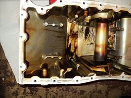
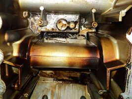
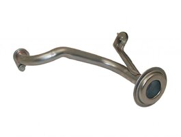
Next, unbolt the Crankcase Oil Pick-Up Tube at the the Tube Insertion Hole in the bottom of the Oil Pump and at the Metal Support and Hold Down Bracket and carefully extract the Tube. Note that there are Bolt Retainers that will keep the two 10 MM Fasteners in place with the Tube and set these items aside.

To Remove the Harmonic Balancer... THE ONLY TOOL THAT WILL WORK is the OTC Model #6667 (6) Piece Kit consisting of the Three Prong Tool with a Female threaded center and three, free-moving pinned arms that will allow you to adjust them into the groove positions shaped into the arms of the Harmonic Balancer. Next it the Hollow Center Pin with Fine Threads that require the application of High Pressure Grease to ease the stress of the thread-lines that will have to pull outwards with around 700 Fit Lbs of Torque in very tiny turning increments. To that is added a set of Heat Treated Steel Pins of varied lengths to allow this Kit a wider variety of applications.

Using the intermediate sized pin that gets stuck down inside the threaded bolt...the Puller Tool is guided with the pin entering to quite a depth inside of the Hollow Crankshaft and allowing the rounded end to seat in the Hollow Dead Center of the Crankshaft...and then the Three Arms must be held in position while inserting the Square end of a 3/8” Ratchet with an adjustable handle into the Square Hollow end of the Bolt… and by tightening slowly until all Three Arms have a good grip on the underside portions of the Harmonic Balancer… as the Tool Snugs up… place your free hand underneath the Harmonic Balancer and gradually tighten down the Black Center Bolt and you will feel the action working as the Puller slide the HB towards you. This will take a few minutes and finally...the Harmonic Balancer will drop off the end of the Crankshaft … right into the palm of your hand… Just… Like … That. Now… set the HB and OTC Tool aside for later inspection and clean-up… (Later on… I’ll be installing a Brand New Harmonic Balancer).

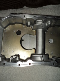
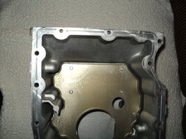
Son now on to removing the Timing Chain Cover … Use the 10MM X 3/8” Drive Socket and Ratchet and slowly loosen all of the Perimeter Fasteners and Bag them as you go along… But keep Two Bolts out to thread into Threaded Bolt Holes located towards the Bottom Outer Flange hollow rectangular pockets and after remove the last Smaller 8MM Fastener roughly centered in the near the middle of the Timing Chain Cover. Then gradually tighten the Two Bolts down until the GM Gray OEM RTV seal adhesion is broken and while being careful not to drop the Front Cover… gently pry it loose by holding the outer edges (these are very sharp and can cut you) and gently lift the cover off of the front of the Engine.

Well … I think that is enough activity for one day … I’m am done in right now and I’m going to try using some Tiger Balm Red on my lower left ankle and the arch of my foot to see if it works to bring down the damned swelling. The videos that follow on from here are the Best onces I have seen on this part of the repair and should be downloaded and saved for repeat viewing for the great information and GM OEM Part Numbers they provide for this job.

This Video shows the OTC Special Harmonic Balancer Puller Tool in Demonstration Action:


And Big Props go out here to Carlos Diaz for his Epic Set of Videos on the Bravada Repair to R&R the Entire Front Components of the GM 4.2L Engine and Replace the Fan Clutch, the Water Pump AND Most Importantly… the Harmonic Balancer, too:

Part 1
Part 2
Part 3
Part 4
Part 5
Not Available on Youtube….

This last video shows a Disaster in The Making from a different VOP if the Crankshaft Bolt should ever come LOOSE:

https://www.youtube.com/watch?v=nH1yRLZJw5Y

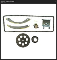
I’m pretty banged upright now… so I might need a few days to “Aggregate My Fecal Material” before moving on with the disassembly of the Timing Chain Set, The Timing Chain Guides, The Timing Chain Tensioner and the VVT Cam Phaser Sprocket, Timing Chain and Intake Sprocket. I will also have to do a dedicated post later that covers Cleaning up all of the Internal Engine areas using GM TEC as well. The R&R of the Engine Head will the “Last But Not Least” of these tasks before re-assembling everything with as many new components, gaskets and sealers as possible to get this engine “Ready for the Road...” Its surprising how clean this motor is inside...I really wish I had an accurate mileage on the Motor to show what one looks like when it “Ages Well”...All In All...THIS Really was a Pretty Damned Good Day!

Much More to Follow…

http://s557.photobucket.com/user/60...NEREPAIR/HARMONICBALANCEREMOVAL?sort=3&page=1
 

mrrsm

Original poster
Lifetime VIP Donor
Supporting Donor
Member
Oct 22, 2015
7,639
Tampa Bay Area
A while back… @Mooseman mentioned in one of his Posts that he had replaced his OEM Gerotor Oil Pump with one made by Melling…. but I’m still not sure if he meant this pump for his Saab GM 4.2L ...or if it was meant for one of his other GM Trucks with a GM 5.3-or> version.

Nonetheless, this made me curious to find out, as I already own a Brand New after-market Gerotor Oil Pump made by Sealed Power (also rumored to be manufactured by Melling for Sealed Power) for the 4.2L LL8 and I would consider using one made with the Melling name on it instead if I could find one. All that aside... while investigating all of the Melling Product Lines for the GM Atlas 4.2L LL8 Motor for the possibility that they also carry the latest upgrades for the entire Timing Chain/Sprockets/Tensioner Set... this link came up:

http://omnitek.co/mellingcatalog/#ag/part/3-195S/from/make=gmc%252Fchevy%2520trucks%2CGmc%252FChevy%2520Trucks&model=trailblazer%2CTrailblazer&year=2004%2C2004&engine=6cyl%25204.2l%2520256cid%2520dohc%2520gas%2520s%2C6Cyl%25204.2L%2520256Cid%2520Dohc%2520Gas%2520S/1

… but if searched on their own Melling Look-Up Page, if you use the search expression “Chevrolet”… you will NOT find this information and/or product line, but rather by searching under “GMC/Chevrolet” to locate all of their “Melling Gear” for the GM Atlas LL8 Engine under Part No. 3-195S:

This will be helpful if this is job you need to get done and are being conscious of both Quality as well as Price… CARID Re-Sells this exact Melling Kit ...for A Lot Less Money:

https://www.carid.com/melling/engine-timing-set-mpn-3-195s.html

After looking over the GM OEM Oil Pick-Up Tube and finding out that Melling makes an OEM Quality version (Fasteners Included) … I found one on Amazon for around $34.00 and “pulled the trigger”… I also ordered a replacement “Blue ‘O’ Ring” for its insertion point into the Gerotor Oil Pump as well… (Can’t be Too Careful… Right?):

I also want to cover an important “Post-Mortem” Artifact of Comparison that is present between the two ostensibly Identical GM OEM Timing Chain Tensioner Components: The OEM Used one I just pulled from this Donor Motor… and a Brand New AC-Delco OEM one I also have that poses the Question:

“Are these two Components IDENTICAL IN PERFORMANCE? Or does the variation in the shapes of their Pressurized Oil Cavity make a difference in how they work against the Timing Chain Guide on the passenger side of the engine… or does the difference change the “hydraulic tightening” dynamic involved as the Oil Pressure rises and falls under normal use?”

I read somewhere that in the Later Model Re-Designed GM Atlas 4.2L Engines that the Depth of Extension of the Nylon padded Tension Plunger had been lengthened inorder to extend the life performance of the Tensioner and maintain better Chain Tension for longer periods between servicing... or failure… but in this case… assuming that this engine is indeed a 2004 vintage motor and not from a later period… I could see absolutely no differences in the quality of manufacture, the metal materials or workmanship used in their making or in their comparative physical dimensions between the two Tensioners when their plungers were at Full Extension that varied in any .

Other than the shape of their Oil Chambers and the obvious indentation pressure wear and brown coloration on the Nylon Pad sustained during the working life of the OEM Old Tensioner they were essentially identical. In fact… were I to spray /polish/clean off the engine heat-stained burnishing and the residual honey-colored Engine Motor Oil and install a Fresh Green Nylon Pad… there would no indications at all that it had not just come out of a GM Parts Box as being Brand New. (Yaay→AC-Delco!)

When I pulled the Crank-Case-Oil-Pan off of the Donor Motor… in addition to discovering that it had NO WINDAGE TRAYS INSTALLED GM ...The OEM Part Number lists this particular Oil Pan as being for a 2005 GM Atlas $.2L Engine… What is up with THAT?… When you think about how plagued these engines are with having so much Motor Oil wind up getting ingested into the Upper Head as Oil Laden Vapors.

Does it not seem related to having the engine whipping the oil around off of the Crankshaft Throws and reflecting off of the openly accessible oil in the pan...instead of being protected by these two flat Windage Trays? Will the Melling OEM Quality Oil Pick Up Tube FIT in and under the Crank-Case Oil-Pan WITH the Windage Trays installed? I mean… WTF...Right?:

Among the other attached images are some comparative views; one from the bottom of the GM 4.2L Crankcase WITH Windage Trays that bears the GM Part # 12579218 and also an image taken from the bottom of the GM Atlas Donor Motor WITHOUT Windage Trays that bears the GM Part # 12584321. I would like to use the one WITH the Windage Tray features if possible.

More to Follow...

Whooooops.... A Post Script!


I just remembered seeing a video recently posted about an "Off-Road" incident where the SUV lost rear traction and had to be pulled out of a deep mud well where something had snagged the under-carriage and I realized what the answer to the "Windage Tray" issue is....and it is a scandal when you think about it:

Just to save a few Green Backs for the modest cost of the Sheet Metal... Then the Stamping out of enough Windage Trays, Holding Grommets-Rivets and the Minuscule amount of Labor involved in finishing up each and every GM Atlas 4.2L Engine with its very own Complete Crank-Case-Oil-Pan... Some "Bean Counter" at GM decided...and I can almost hear his voice as he tells his Boss...

"Boss... Guess What! We can save a lot of money by NOT putting Windage Trays inside ALL of the Crank-Case-Oil-Pans of each and Every SUV we Sell... WE JUST HAVE TO INSTALL THEM IN THE ONES WITH FOUR (4) WHEEL DRIVES!" ... and then he hears:

"Nice Work... My Boy.... Here Son... Have a Cigar... and take 30...MAKE THAT 10 Minutes Off...Next Friday... Yes?"
 

Attachments

  • DSC03827.jpg
    DSC03827.jpg
    481.4 KB · Views: 7
  • DSC03833A.jpg
    DSC03833A.jpg
    257.2 KB · Views: 9
  • DSC03834.jpg
    DSC03834.jpg
    196.8 KB · Views: 8
  • DSC08054.jpeg
    DSC08054.jpeg
    171.5 KB · Views: 10
  • DSC08070.jpeg
    DSC08070.jpeg
    174.2 KB · Views: 10
  • DSC08071.jpeg
    DSC08071.jpeg
    187.8 KB · Views: 10
  • DSC08229.jpeg
    DSC08229.jpeg
    141.6 KB · Views: 8
  • DSC08230.jpeg
    DSC08230.jpeg
    123.1 KB · Views: 9
  • DSC08232.jpeg
    DSC08232.jpeg
    125.5 KB · Views: 10
  • DSC08233.jpeg
    DSC08233.jpeg
    119.8 KB · Views: 9
  • DSC08235.jpeg
    DSC08235.jpeg
    144.1 KB · Views: 11
  • DSC08237.jpeg
    DSC08237.jpeg
    154.4 KB · Views: 12
  • DSC08238.jpeg
    DSC08238.jpeg
    113.4 KB · Views: 12
  • DSC08240.jpeg
    DSC08240.jpeg
    106.4 KB · Views: 13
  • DSC08241.jpeg
    DSC08241.jpeg
    119.7 KB · Views: 11
  • DSC08246.jpeg
    DSC08246.jpeg
    93.5 KB · Views: 13
  • GMOEMCRANKCASEWITHWINDAGETRAYS.jpg
    GMOEMCRANKCASEWITHWINDAGETRAYS.jpg
    84.2 KB · Views: 12
  • GMOEMDONORMOTORCRANKCASEWITHNOWINDAGETRAYS.jpeg
    GMOEMDONORMOTORCRANKCASEWITHNOWINDAGETRAYS.jpeg
    171.5 KB · Views: 14
  • MELLING358SOILPICKUPTUBE_.jpg
    MELLING358SOILPICKUPTUBE_.jpg
    37.5 KB · Views: 10
  • MELLINGTIMINIGCHAINSETBIGIMAGE.jpg
    MELLINGTIMINIGCHAINSETBIGIMAGE.jpg
    38.9 KB · Views: 6
Last edited:

Mooseman

Moderator
Dec 4, 2011
25,257
Ottawa, ON
A while back… @Mooseman mentioned in one of his Posts that he had replaced his OEM Gerotor Oil Pump with one made by Melling…. but I’m still not sure if he meant this pump for his Saab GM 4.2L ...or if it was meant for one of his other GM Trucks with a GM 5.3-or> version.

It was actually my 5.3L Saab. I replaced the oil pump at the same time as the valve train while eliminating the DoD/AFM components. It was a Melling standard volume pump. I do have an issue with it as it has less pressure than the original pump. So much so that I got a code for it when the oil was at 40% life left (probably a vestigial code for the DoD system). An oil change took care of that. The pressure is lower throughout the RPM range. The 5.3L (actually all LS engines) have a history of failing pressure relief valves and pickup tube o-rings, which is why I replaced it. Even though Melling is a very reputable name, I should have gone with ACDelco or OEM.
 

mrrsm

Original poster
Lifetime VIP Donor
Supporting Donor
Member
Oct 22, 2015
7,639
Tampa Bay Area
@Mooseman …Thanks for that clarification… And based upon your information… unless I can see some obvious weakness in the material that the Sealed Power one displays when set out side by side with the OEM Donor Motor Oil Pump (photos are pending) and I can see “Thinner Castings, Rough Machining and Smaller, Cheaper Fasteners...” I will be installing the NEW one as at least I know that if the OEM Donor Motor Gerotor Oil Pump has not failed… Yet… I would just as soon avoid the remote possibility that the Oil By-Pass Valve will be going “T*ts Up” two weeks after I button up this engine. Going cheap on ANY component that is going into an engine like this after tearing it down this far is the mark of insanity. Nope… Not gonna risk it!

Hey... I’m Sorry… But THIS Technical Topic requires a “Necessary H/J”:

And so in the same vein of “Why not fix it NOW while you have the chance… Right?” On the subject of the value of having a Windage Tray inside of any engine… Here are a few relevant quotes from this link… and no… the fact that these guys are discussing Mopar Motors is immaterial… the actual NEED TO HAVE ONE INSIDE THE GM ATLAS 4.2L LL8… is the issue I am concerned about. Hell ... just look at the “Oil Sling” cleared spaces on the inside of the Donor Motor engine block walls that show up in the “copious amounts” of images I saved in my Photobucket. Those images clearly indicate how much high velocity the Motor Oil is under after it moves through the Oil Galleys at 65 PSI and exits as a high pressure spray out from the areas between the Babbitt Bearings and the Crankshaft Journals at anywhere from 600 RPM at idle… all the way up to 5,000 RPM. Do you think any of that Oil is actually in any other condition than a “Brown Mist” down there after of all that hectic activity and eventually make its way back down into the Oil Pan? Hell’s Bells… The Gerotor Oil Pump in this Motor pump is capable of pumping out over 11 Gallons per Minute… again and again and… well… You’ll get a better picture of what can go wrong when this is happening from these excerpted comments:

http://forums.hotrod.com/mopar-muscle-magazine/70/7141434/mopar-engines/what-is-a-windage-tray/

A wind-age tray is usually a stamped piece of sheet metal that is mounted between the crank shaft and the oil pan. On slow revving i.e. stock applications there benefit is slight. However race and high RPM applications claim that they actually free up more horsepower. When the crankshaft is rotating say at highway speed a horizontal vortex of swirling air is generated. The oil in the engine that was pumped up high and residual from the crank assembly is draining back to the oil pan gets caught in this vortex and is spinning too. Some estimate that anywhere from 1 to 3 quarts of oil can be caught in this vortex. Which leads to why a wind-age tray is such a great thing. (1) this much swirling oil acts like a small load on the engine and robs Horse Power. (2) with that much oil NOT in your oil pan at High RPM you could have a potential oil starvation or cavitation problem, KABLOOWE. A wind-age tray acts like a scraper and removes the oil from the vortex letting it drain back to the oil pan. It does not actually touch the crank shaft but it is close enough to it to skim off the oil and let it drain.”

Just imagine those big crank counterweights and connecting rods spinning just above a pool of oil 100 times a second. It creates a bit of a vortex as you might imagine. It's bound to pick up at least a mist of that oil and carry it around with the spinning assembly, right? Well, it's worse than that-it can pick up a whole lot of the total oil capacity at high rpm and just kinda wrap itself up in it in an extreme situation. That creates a lot of drag on the spinning assembly, and might even uncover the pickup so you lose oil pressure. Part of the reason for deep-sump designs is not just to increase oil capacity, but to move it down away from the crank. If you could move the oil level down 10" you wouldn't have much of a problem, but you can't because of ground clearance. The tray and any other pan baffling are about oil control. The baffles seek to keep it from sloshing out of the pan from G-forces, and the tray seeks to separate the oil reservoir from the crank as much as possible-making the reservoir a semi-sealed package. They even use crank scrapers that are cut to just clear the crank and rods and skim off any excess oil. All this is why the ultimate bucks-up builds use a dry sump system with the oil kept in a separate tank when rules allow. Most of the power savings are at higher rpm levels as you might imagine. Milodon has long been a Mopar favorite and has good pans and trays. The MP tray can stand to have the drain-back louvers bent open a bit more. I would start building a little library of engine building books and you can peruse whatever subject at your leisure-always good reading for a Motorhead.”


One last Rhetorical Question before I never mention “Windage Tray” again… (I Hope…)

WTF are the Support Pins that HOLD UP AND ANCHOR THE WINDAGE TRAY still doing inside of the Cast Crank-Case-Oil-Pans that do NOT have them if the Windage Tray is an unnecessary “homologous structure”…? Jesus Palomino, come ON General Motors… WTF is wrong with your Engineers…? Haven’t they ever SEEN the Black, Soupy Crappy Oil that collects inside of the Intake Manifolds and the Intake Ports in the Engine Head of the LL8 I-6 Engines? … No? Oh right… Silly me… We’re supposed to install a Brand New, $4,000.00 Re-Manufactured Motor to solve THAT particular problem, Huh?… Geeeeezusss.
 
Last edited:

mrrsm

Original poster
Lifetime VIP Donor
Supporting Donor
Member
Oct 22, 2015
7,639
Tampa Bay Area
Well… I've had a very hectic and involved day working on and inside of the Donor Motor and I’m paying the price in serious discomfort right now… But having covered so much ground with this Engine … I’m documenting everything while its still fresh in my mind:

http://s557.photobucket.com/user/60...REPAIR/GM42LENGINEGTEARDOWN2017?sort=3&page=1

I started out with intention of just denuding the front of the Engine Block of anything and everything that needs to come off and I wanted the Photo-Play to reflect that in an organized manner so that the steps will be easy enough for anyone to carry on with. My experiences with this amazing power plant are unique in so many ways; the most unusual being that very few of us will never get the chance or have any inclination to take this Motor down to its Skeleton and vivisection even one of these engines... let alone two of them.

But the Price of Admission on the “GM Atlas ‘E’ Ticket” ride is a steep one... and nothing you do that leads from the first component R&R to the last will come Cheap...and these repairs will not unfold in a manner that is all that pleasing unless you are willing to spend the time and the money to just keep going. When I finally decided to obtain a “Swap-N-Drop” Engine… it was because my domestic circumstances pressured me to move on from just replacing the Engine Head on my son’s 2002 4.2L Trailblazer; an obviously daunting enough task all by itself… to getting a very good deal on an Engine that just keeps bringing a smile to my Ugly, Old Face… even though the “Mechanical To-Do List” has grown steadily over the last three or four months.

If only Life were Linear… moving from the beginnings of these projects and progressing rapidly to their successful conclusions in a very straightforward manner… because if they did… we could all enjoy the “doing” of these Wrench-Turning Tasks with less stress and more of a chance to step back and admire the idea that these Atlas Engines will never be able to “shrug” us off or defeat our abilities to make our GMT-360s whole again. Nothing short of an unexpected “Dirt Nap” will stop me from getting this machine to do my bidding… and so even though the work is challenging… I still believe that any of us with good, critical thinking skills and the Mechanical Vulcan Mind-Meld we often must do as a team will overcome damned near any problems that get in the way.

As I said… the images will be easy to use as the means to follow what was removed from the engine block and without belaboring every single move I made… if you look the photos over ...you’ll get the “Whole Picture”. I would suggest to anyone that is disassembling this Motor… .to make sure to photograph everything on the block from every useful angle you can think of BEFORE you touch anything, as most of the re-assembly imagery in the shop manuals and the usual GM “Stick Figures” will not show you what your unique situations look like.

Likewise… I know its a boring and tedious job for anyone not really interested in doing mechanical repairs as an exercise in improving their knowledge or as a vocation… but try to stage-shoot everything as you tear down the engine and fix these images so you have a visual library to come back to if the project gets delayed by days...weeks...or as in my case… months on end. You won’t remember everything you did... and so you won't regret having “Tagged and Bagged” absolutely everything you remove and then stored inside a Giant Coleman Cooler that you can close up tight and keep out the weather, the critters , the dirt and dust...and The Rust that will settle on Cast iron and Steel parts and pieces in neglected in any way.

Remember this… Once you put YOUR images out and about and available to the world at large… there will be thousands of people who will visit your work… seeking help, guidance and some way to boost their flagging confidence when the jobs get really hard. I let everyone in on what I am doing because it means a great deal to me that my stuff might be just what the viewers must have and not have to either pay anyone or beg anyone or be ridiculed by anyone for any lack of mechanical acumen.

Back to today’s events…
I managed to unbolt the Engine Head and remove it this evening… But the Ghost of Broken Head Bolts paid me a visit with the Vengeance of Jacob Marley inside my Garage. Not matter that I had the Engine on a stand and can recommend this work to be done only in this manner. Yet … I as Hammered dutifully on each Head Bolt with the H-10 1/2” Hex Tool fitted with a 1/2” ‘Sacrificial Adapter”… when it came time to slowly and carefully “Put the Music” to my Giant 1/2” Breaker Bar… it made no difference in the end. To say that “Six Bolts Broke...” is THE Understatement of 2017. They didn’t just Break… They Exploded! I literally could smell the smoke of the violence dealt each one as they snapped with sound like .357 Magnum fired inside of a room.

It was very reminiscent of the metallic smoke smell of “Flint Strikes On Steel” when it happened. But this is where my prior experience comes into play, knowing now that I should have just continued with this process way back when I was working under the Trailblazer hood and just pulled the head off first… before attempting any Broken Bolt Extractions. That will tomorrows efforts if I can navigate around little better. It was AMAZING to see this engine’s clean and tight condition once I got it all taken apart. There is simply NO WAY that this engine was driven for 160,000 Miles… Nope … It is not possible. The carbon coating on the pistons was so thin and soft… that I could wipe it off with my bare fingers! And that Engine... The Pistons… The Bearings... The Top Compression Rings … they are all Tighter than Two Ticks in a Hunting Dog’s Ear!

I sprayed down everything Ferrous with a liberal dose of “Cutting Oil’ because I was touching and checking everything and I don’t want any of the Oils or Amino Acids in my Salty Sweat to wind up putting “Rusty Fingerprints” on anything. Tomorrow I’ll get busy with beginning the HUGE job of cleaning up this Motor inside and out… and Duct Taping up the Old MLS Head Gasket to block off all of the passages in the Engine Block so that no Oils and Solvents and GM TEC invade where these sprays should not be allowed to go. I’ve got to get some rest soon… so I’ll clean up, re-size and post the images of today’s progress on my Photobucket. I’ll go over some more things of interest that happened so far in a short while that need explaining and we’ll see what the engine look like when we can all observes the “innards” ...right down to the Bare Aluminum.

More to Follow….

http://s557.photobucket.com/user/60...REPAIR/GM42LENGINEGTEARDOWN2017?sort=3&page=1
 

mrrsm

Original poster
Lifetime VIP Donor
Supporting Donor
Member
Oct 22, 2015
7,639
Tampa Bay Area
I'll cover a few observations about yesterday's Engine Disassembly that bear mentioning because if nothing else... these are all very curious artifacts to be found inside of this engine. First up is the overall "Clean, Dark Honey" condition of the motor oil that I drained out of this engine and almost complete absence of any sludge. The general areas outside of the "Big Rectangular Basement" where the whirling Rotating Assembly swirled around enough oil to literally "spay paint" all of the areas beneath the bottom of the cylinders, and on the Main Crankshaft Engine Block bosses and the cradle as well as the sides of the box interior.

However... after being drained of at LEAST a quart of residual Motor Oil that was also "Honey Brown" and clean enough to easily see daylight through... with the exception of some isolated spots where the oil simply could not escape once it settled down inside... every other area was free of any "sticky" Sludge or Black Oil and in all of the upper block and the cavity behind the Front Timing Chain Cover... was also so clean that all you could see was Bare Aluminum.

These were not simply externally, superficially "clean" surface conditions here, as when I removed the CPAS Solenoid from the Engine Block from its VVT tube insert location inside of the Engine Head... all of the screens on the Solenoid were perfectly clean and patent. So the indication of this is that right along with having No Sludge Deposits at all in any of the opened oil galleys or insertion points for the Gerotor Oil Pump into the front bottom of the Engine Block ...everything involving lubrication is just as clean inside as well as out. The Oil Filter Autopsy results are also consistent with the observations of these conditions, indicating that the prior owner rendered an almost fastidious level of Perfect Care for this Engine... right up to the very instant of his unfortunate crash event that totaled the vehicle.

The Lack of any serious wear on any of the internal components; including the entire Timing Chain Set, also supports the idea that this engine had almost perfectly maintained working conditions and a lack of hard, heavy footed or extravagant behavior at any time, So the prior owner apparently took an almost religious reverence with his care and keeping of the Donor Motor... and while I'm loathe to profit from any man's misfortune... I could not be more grateful for the way he treated his Donor Vehicle. In my mind... he is still a vicariously Honored Member in Absentia.

When I removed all of the Timing Chain Set Hardware... I found an unusual 'Steel Shim" around the slotted exterior "gear" that plugs into the inside of the Gerotor Oil Pump... apparently giving it a very slight separation between the face of the front of the Crankshaft Gear-toothed plate...and the back of the matching female "Teeth" of the Rotor Impeller that powers the two eccentric Gerotor Pump gears. I have never seen this "shim" ever referenced before and I am curious as to whether I will need to install it when I R&R the OEM Gerotor Oil Pump with the New "Sealed Power" Oil Pump.

In anticipation of the dreaded but necessary "Broken Bolt Extractions" that must be carried out with all of the hindsight I bring to the issue from my prior experiences in dealing with making mistakes while attempting the job... I found a boon in the way of NOT having to spend the exorbitant amounts expected for the Kent-Moore (@Mooseman would say "Spent-More" Tool Kit... I think I can get the one part of the kit that cannot be reasonably substituted in any way and NOT screw up the Aluminum Engine Block...and that is to purchase JUST THIS PART and NOT the entire Kit. This is possible now because OTC manufactures them and sells them for Pennies on the Dollar. So while I am waiting for this Tool to arrive... I'll continue with the plans for cleaning and preparing the Engine Block to accept as many New Parts as I can throw at it and have them "stick"... ;>) These are the folks who have come to my rescue and the procedures follow on from here:

USA Tool Warehouse had “THE Single Most Important Tool” out of the $400.00 Kent-Moore EN-47702 Kit…. Made by OTC as an Identical Sub-Kit Part # EN-47702-1 which is the Head Bolt Centering Tool… all of the other tools can be found elsewhere or are already available somewhere in all your Tool Boxes…

...and it only costs $22.50 + S&H

and you just can’t ask for more than that to guarantee that when you begin drilling out a hole for the Carbide EZ-Out … you will NOT “Booger-Up” the threaded Head Bolt Holes involving however many unfortunate Head Bolts have broken off inside of the Engine Block. This item can be purchased at the link below:

http://www.usatoolwarehouse.com/usatoolwarehouse/OTC-EN-47702-1.html

http://www.engineprofessional.com/TB/TB021615-1.pdf

#05-06-01-026B: Information on Torque to Yield Bolt Breakage and Use of Bolt Extractor Tool Kit Part Number EN-47702 for Removing Broken Cylinder Head or Main Bearing Cap Bolts on In-line Truck Engines - (Oct 21, 2008)

Subject: Information On Torque to Yield Bolt Breakage and Use of Bolt Extractor Tool Kit Part Number EN-47702 for Removing Broken Cylinder Head or Main Bearing Cap Bolts on In-line Truck Engines

Models:

2004-2007 Buick Rainier
2002-2009 Chevrolet TrailBlazer
2004-2009 Chevrolet Colorado
2002-2009 GMC Envoy
2004-2009 GMC Canyon
2002-2004 Oldsmobile Bravada
2006-2009 HUMMER H3
2005-2009 Saab 9-7X
with 2.8L, 2.9L, 3.5L, 3.7L or 4.2L Vortec Inline Engine (VINs 8, 9, 6, E, S -- RPOs LK5, LLV, L52, LLR, LL8)


This bulletin is being revised to add model years. Please discard Corporate Bulletin Number 05-06-01-026A (Section 06 -- Engine/Propulsion System).

A Torque To Yield (TTY) bolt, like a cylinder head bolt or main bearing cap bolt, may break during repair procedures. Interaction between a TTY bolt and threads may cause the bolt to bind or break on removal. Prior to removing the cylinder head or main cap bolts, perform the following procedure:

Using an appropriately sized punch and hammer, rap on the head of each bolt. The vibration produced by this procedure will assist in successful removal. if a head bolt or main bolt breaks during engine disassembly, a broken bolt extractor kit (EN-47702) has been released to assist in removal of the remaining bolt segment. Many times the remaining bolt segment will back out easily with a pick tool or a reverse twist drill bit.

Bolt Replacement & Tightening

Important: Never reuse TTY main bearing or cylinder head bolts. Always make sure that the engine block threaded holes are clean and do not place oil or thread-locker on the bolts.

Utilize a thread chase tool followed by cleaning with dry compressed air to insure threads are clean and dry prior to installation of new TTY bolts. Bolts that creak and snap while tightening will fail due to excessive torque caused by threads contaminated with debris, antifreeze or oil. Trace amounts of oil or antifreeze will cause this condition. In extreme cases the threads may need additional cleaning with a non-residue cleaner like a brake clean product followed by drying with clean & dry compressed air.

The bolt extractor kit EN-47702 provides the following components to assist in removal of the broken bolt segment:
  1. One 5/32" reverse twist drill - part number EN-47702-6
  2. One double-ended drill pilot insert - part number EN-47702-1 (ensures a straight drilling procedure)
  3. Drill pilot inserts for larger diameter heads or main cap bolts - part number EN-47702-2 (ensure a straight drilling procedure)
  4. Bolt extraction #3 EZ out - part number EN-47702-3 (after the drilling procedure)
  5. Bottom tap (M11 X 2) - part number EN-47702-5 (for the head bolts to chase the threads after the completion of bolt removal)
  6. Bottom tap (M10 X 1.5) - part number EN-47702-4 (for the main bolts to chase the threads after the completion of bolt removal)
 

mrrsm

Original poster
Lifetime VIP Donor
Supporting Donor
Member
Oct 22, 2015
7,639
Tampa Bay Area
Okay… Everybody knows about my insistence on “..Sticking with OEM Engine Parts...” and in most cases… this is it for me. But being an “OEM Parts Purist” may not work for everyone if:

(A) “The Parts are Just Too Expensive as a GROUP of the ones I need to do the whole job and NOT Break my Budget...” or…
(B) “Using Only OEM Parts would be my preference, too… If only I could FIND the OEM Parts...”

The Case in Point this evening has to do with some Parts Purchases I made at the ‘knee-jerk’ stage of working on the 2002 Trailblazer way back in January of 2015… Just before the TB crippled me… and I was trying to be economical well before becoming an “Edified, Well Informed GMT-Nation Member” and ‘Aggregate My Fecal Material’ about what MUST be used for parts whenever working on the Atlas LL8 Engine. And so… I bought a “Timing Chain Tensioner Kit” from EVERGREEN off of eBay that eventually lead me to question the wisdom of my purchase right after a thorough scolding from @Mooseman about the Error of My Ways.

It followed on that I began the steady and sometimes unnerving process of wearing out my Tri-Fold Wallet by constantly reaching deeper and deeper for More Money to pay for any number of the necessary OEM GM, Delphi or AC-Delco Components that these repairs demand. And in the case of comparing the Quality and Finish of say… The EVERGREEN Timing Chain Tensioner Vs. The AC-Delco OEM Timing Chain Tensioner… Well… My GOD! The differences were downright SCARY when observing the difference of how the materials appeared; with the AC-Delco using High Quality Steel, High Quality Pre-Casting Investments, the use of New Machine Tools for Shaping and Post-Processing Machining ...Vs.... the EVERGREEN using Lousy Scrap Metal, NO Proper Pre-Casting Design Shaping and Post-Processing Routing (Drilling?) and Shaping done with Old, Damaged Tooling that looked like the work was done with an “Etcha-Sketch” by a Mechanical Beaver using Busted Front Buck Teeth!

You Folks can be the Judge. You don’t need to be Manufacturing Quality Assurance Technicians or a Metallurgists to look at them and determine which is the BETTER of these two after-market Timing Chain Tensioners from the “INNER FIRE Company” Vs. “EVERGREEN” . So the fact that this Higher Quality and Lower Priced Part is being offered on Amazon.com for Only $15.00 prompted me to want to get TWO of them just so I could look both over for their consistencies (or lack thereof) and then have them around “In Case of an Emergency” if I had an OEM Tensioner Fail. But mostly... just because I wanted to see how One After-Market Parts Maker for our Engines compared against another After-Market Parts Maker that cannot prove that they can Pass Muster as an OEM Quality Part… Or maybe just one of these two… Might Make The Grade... In a Pinch.

http://s557.photobucket.com/user/60...PAIR/GM42LTIMINGCHAINTENSIONERS?sort=3&page=1

So now ...you can decide if you either want or need to get one of these (10) that they still have left on the outside chance that, God Forbid… You might need a New Timing Chain Tensioner and the OEMs become unavailable or if you’re like me and you don’t mind dropping $15.00 so you can find out for yourselves the answer to the Burning Batman Question:

Why... So... Serious…? “ about a Timing Chain Tensioner? ;>) Here you go:

https://www.amazon.com/Chevrolet-Hummer-Oldsmobile-Tensioner-IF-95512/dp/B00WY17PLK/ref=au_as_r?_encoding=UTF8&Make=Chevrolet|47&Model=Trailblazer|489&Year=2004|2004&ie=UTF8&n=15684181&newVehicle=1&s=automotive&vehicleId=1&vehicleType=automotive

PS: This is my First Opportunity to try out my new Sony CyberShot DSC-W290 Digital Camera!
 

Attachments

  • DSC08434.jpeg
    DSC08434.jpeg
    111.9 KB · Views: 2
Last edited:

mrrsm

Original poster
Lifetime VIP Donor
Supporting Donor
Member
Oct 22, 2015
7,639
Tampa Bay Area
The Melling New Oil Pump Pick-Up Tube Arrived and it looks identical and has the same High Quality design and welds as the GM version. It came with the Elliptical Washer-Sealer Gasket with both High Grade Fasteners attached and held with retainers to prevent them from being dropped when the installation is being done inverted under the vehicle.

However, Just to be clear about the Gerotor Oil Pump "Apples Vs. Oranges" ...Differences that can crop up:

For the "OLD" GM OEM Gerotor Oil Pump Design:

The Oil Pickup Tube is NOT a Universal Component and is NOT compatible with the Latest Gerotor Oil Pump Design... and has a rather has different Tube insertion point than the latest version. It features a submerged groove machined inside the Pick-Up Tube Port in the bottom of the pump that encircles a "Beefy" GM OEM "Blue" Silicone 'O' Ring identified as Part # 12557752. This "Blue Ring" should be replaced... even if the Old, Used one "Looks Real Good". It's a Ten Dollar expense worth paying for to get the "Peace of Mind" of not allowing the OEM GM Gerotor Oil Pump to lose suction...cavitate...and destroy the engine in no time flat. Very soon now... I'll show these components in a separate Photo-Play as soon as I clean up and 'Autopsy' the Front Timing Chain Cover and R&R The "OLD" GM Gerotor Oil Pump in readiness to install the Brand "NEW" Sealed Power that is the "Updated" Flavor.

For the "NEW" Updated Designed Sealed Power (2004-> GM 4.2L LL8 Engines):

The Sealed Power Gerotor Oil Pump featured at the link below IS designed for the Latest Type of Pick-Up Tube from Melling which features a 'Built-In' elliptically shaped "Gasket on a Bracket Plate" that encircles a much lengthier portion of the Tube deeper inside of the Sealed Power Gerotor Oil Pump. Like the 'plate'... the new pump has no submerged groove inside the base of the pump but instead, it has just a smooth channel to encircle the longer insert pipe and a flat, wider surface area to provide a larger, smooth surface area for the New 'Gasket on a Bracket" to get squeezed against and contain the Engine Oil under a Vacuum, allowing the Rubberized Material to do the sealing. Why this design is supposed to work any better than the "Original Crispy..." one from GM is any body's guess. But... there it is... If you want "The Updated Gerotor Oil Pump"... you must also purchase an "Updated Oil Pick-Up Tube" as well. Here are the links for both of these components.

Sealed Power Gerotor Oil Pump -- with precautions mentioned on the Install Instructions:

http://s557.photobucket.com/user/60...AZERENGINEREPAIR/GEROTOROILPUMP?sort=3&page=1

Melling Gerotor Oil Pump Pick-Up Tube:

http://s557.photobucket.com/user/60...ENGINEREPAIR/GM42LOILPICKUPTUBE?sort=3&page=1

I am finding it very hard to attach more readily available images here... so I'll have keep using these visual updates linked back courtesy my Photobucket until things get figured out here on the GMT Nation site.
 
Last edited:

mrrsm

Original poster
Lifetime VIP Donor
Supporting Donor
Member
Oct 22, 2015
7,639
Tampa Bay Area
When last we met… I had sprayed down the inside of all the Donor Motor Cylinders with “Cutting Oil” to keep them from rusting over the few days when the motor was unattended and while waiting for the “OTC Bolt Extraction Drill Guide” to arrive. The other purpose for doing this was to observe whether or not the Oil would drain down completely and give any indication of either Cracked Pistons or Excessively Worn Rings. I am happy to report that the Oil pooled on the tops of the pistons and remained there for the duration.

Because of an ongoing GMT Nation thread about the issues presented with GM OEM Thermostats and Temperature sensors here:

http://gmtnation.com/forums/threads...at-replacement-on-inline-6.14038/#post-525315

… I wanted to do a side by side Photo-Play to look for any subtle differences or problems between the AC-Delco OEM version and the Stant flavor of this thing… and there are some design variations between the two that puzzle me and make me wonder whether or not the AC-Delco one I am considering using will give me any trouble. I am heading out to the garage shortly to prep the Old MLS Gasket with Black Duct Tape to block off everything except the (14) Head Bolt Holes ...with two having the Head Aligning Tubes to get around.

As I perform the Solvent Cleaning procedure, I’ll be using the two cans of AC-Delco Top Engine Foaming Cleaner that arrived this morning. I’ll also be using some “Canned Air” I have on hand that really makes it easier to blow out any debris that needs moving from the engine “innards” to the absorbing towels and not have a Noisy Compressor for the occasional need for compressed air.

When I finish removing the OEM AC-Delco Thermostat presently installed… I’ll photo-compare the two and look for anything unusual between the two that might indicate that the BNIB one I just got from GM is “sketchy”...or not. Its troubling to imagine OEM Components from any of the “Big Three” Parts Vendors being both Brand New ...and Suspicious in failure so soon after Installation.

The same kind of question about performance and endurance lingers for the Oil Pressure Sensor as well. I took some images of the Old Intalled OPS and have a Brand New OPS from Dayton that I have never used and wonder about being up to the OEM Quality Flavor, too,

I took some close up images of the Coolant Temperature Sensor located in the upper left side of the block and have some questions about the correct replacement for it. I have been following the below listed thread on the topic of Thermostats and also ...Temp Sensors, etc. and observing @xavierny25 ‘s information that is good to know and I hope that it applies to this Motor:

http://gmtnation.com/forums/threads...at-replacement-on-inline-6.14038/#post-525315

Again… It is such a great relief to get back to taking good images without the “Smoky Ghosts” obscuring the details. I like to have the this work very well visually referenced as I move through the build and so the latest photos related to this specific work can be seen here and I’ll add updated images relevant to each sub-album as I go along and the Engine becomes fully assembled:

http://s557.photobucket.com/user/60...ZERENGINEREPAIR/GM42LTHERMOSTAT?sort=3&page=1
 
Last edited:
  • Like
Reactions: W4UWC

mrrsm

Original poster
Lifetime VIP Donor
Supporting Donor
Member
Oct 22, 2015
7,639
Tampa Bay Area
Before catching up… It will be helpful to view the Photobucket images of Today’s Recorded Work ...First:

http://s557.photobucket.com/user/60...RENGINEREPAIR/GM42LPREP4REBUILD?sort=3&page=1

Having Photo-Recorded the comparisons yesterday between the AC-Delco and the Stant Atlas LL8 Engine Thermostats before removing the one installed inside of the left side of the Block… I knew which one had been installed as a replacement as soon as I unbolted it and pulled it out (Stant). It was NOT the one that the Factory had put in and therefore indicates that the component had to be replaced at least once. Apparently… the Original Owner didn’t dig the OEM one that failed and had to come out and chose the Stant flavor instead. And so my comparison side-by-side images have proven useful in the 'autopsy' of this engine during its Tear Down and answers more questions for anyone who wants to find out what to look for in the absence of any Names or Numbers on their Thermostats.

Today we have made more progress involving the clean-up and mask-off of the Old MLS Gasket as a Necessary Evil in preventing either Strong Solvents (AC-Delco Top Engine Cleaner) or shards and bits of Steel Drilling Tailings from dropping inside the exposed holes in the Upper Engine Block. This protection will be important during the coming efforts at removing (7) of the (14) Head Bolts I broke off during the removal of the Aluminum Engine Head.

This Duct Taped Barrier will protect and cushion the top of the Engine Block Mating surfaces from the impact of tools in motion (errant Drilling) or from anything that accidentally gets dropped from altitude, risking nicks and damage that would otherwise ruin the Engine Block for use. After installing the Duct-Taped MLS Gasket… the cylinders were filled with AC-Delco Top Engine Cleaner... and will demonstrate why I have been touting the use of this stuff to be sprayed down inside the LL-8 Engine Spark Plug Holes of fully assembled and engines capable of running as well. After being allowed enough time to "Put the Music" and soak long enough to dissolve all the inside Carbon Deposits, the Black Goop can be vacuumed clean before re-installing the plugs. After this spray down shown in the attached photos has a chance to "contemplate the carbon" for a while... I'll show you just exactly how GOOD AC-Delco Top Engine Cleaner is for this job.

(Thanks God for @Mooseman's original suggestion...)

The MLS Gasket must be washed with Dawn Dish Soap and any loose MLS Rubber Sealant must be thoroughly scraped off BOTH sides with a Razor Blade. Then the item gets a second dowse of Hot, Soapy Water and should be laid out on top of Newspapers covered with Scott Towels on the top and bottom surfaces and after walking on this stack for a minute or so… most of the water that got sprayed in between the two halves will get thoroughly squeezed out.

After that ...you can concoct whatever arrangement of lengths of Duct Tape on BOTH sides of the MLS Gasket as long as the pieces of tapes cover every opening except the six cylinder holes. After squeezing the tape together on both sides… one last “walkabout” with the MLS laid out on the deck under sections of News Print… the tape will bond well enough together to withstand practically every torture you decide to put it through during Upper Block Preparation.

Next up will be the job of carefully carving out the Duct Tape from inside of the TOP and BOTTOM of the individual (14) Bolt Holes; making that (28) necessary cuts with several Razor Blades that will demand your undivided attention. If you are smart… you’ll probably be working on a low bench and NOT free-lancing with the MLS Gasket parked in your lap… as it will be very easy for the Razor Blade to slip with so much activity. It would be a very unfortunate outcome indeed, if you should wind up accidentally Gelding yourself. (Please… Be Careful here...)

The next thing to do is to lightly wipe down the surface of the Engine Block (the thorough cleaning of it will be almost the last work done) and install the Duct-Taped Modified MLS Gasket onto the head..using the Two Alignment Tubes of the Left side of the Engine Block to guide it right back in place… noting that the Duct Tape will help to secure the MLS Gasket in the Down Position.

A Word or Two About TTY Fasteners:

While my recent unfortunates experience with breaking off so many Engine Head Bolts is so fresh in my mind... I should mention that over in another Thread where this topic is also contemporary... I've encountered a difference of opinion concerning the Re-Use of TTY Bolts of a Larger Size. And while I cannot argue with the experience of better Mechanical Minds than my own. I'd at least like the chance to point out some important considerations here (without having them being summarily deleted from this post) that might turn a few heads into re-considering the wisdom of re-using any of the larger flavor TTY Bolts:

(1) The Bolt Length is increased during the first encounter with Final Tightening with all TTY Bolts and this dynamic serves to “neck down” the bolt steel, making it extremely brittle throughout its entire length.

(2) Any Thread Lines either cut or rolled into the shaft of the Steel Bolt (in this case, having the Head Bolt Dimensions of M11 X 2.00MM) will get changed, because the threads become separated wider and wider from one another as the TTY action stretches the Bolt. This is probably the biggest reason why some of the Head Bolts in the Atlas LL8 become impossible to “UN-screw” and more or less get solidly wedged tightly inside of the Engine Block Bolt Holes... that they MUST fail as they get “Reverse Torqued” and backed out of the Engine Block.

(3) While you might get away with re-using a Large TTY Bolt a Second Time… if it turns out that you are very unlucky ...and that Bolt Breaks or Snaps Off… Your already difficult job of removing and re-installing the very same bolt is now compounded 1,000 Fold…. This will happen because of the additional problem of the need to first extract the broken piece remaining inside of the Engine. In the end… if this Aluminum Motor does not get damaged or ruined during all the extra labor… You will STILL need to obtain a Brand New TTY Bolt to replace the “Re-Usable” Broken One.

To support my position more dramatically… this video demonstration shows a perfect example. Here, these two Geeky VOPs (Video Original Posters) are using a HUGE section of Phosphor Coated “Gray Bar” Construction Steel Re-Rod as an example of what happens to a TTY Bolt as it enters its Final Stage of Tightening and begins to suffer “Plastic Deformation”. The outcome I wanted to show here is just about as close as I can come to what it feels like with your hands wrapped around the handle of a BF 1/2” Breaker Bar and an H-10 Hex Socket plugged inside of the GM 4.2L Engine head Bolts when you are trying to “Unwind” these Torque To Yield Fasteners… and they get stretched beyond their Elastic Yield Points. THIS is What Happens:

(...Its FUN to Watch here... But NOT MUCH FUN to experience... for REAL)

 
Last edited:

mrrsm

Original poster
Lifetime VIP Donor
Supporting Donor
Member
Oct 22, 2015
7,639
Tampa Bay Area
Okay… This is an update on how the Preliminary Piston/Rings/Cylinder Clean-Up and Lower Engine Block Cleaning progressed today. These images have been added to Yesterday’s Engine Prep Photobucket Album:

http://s557.photobucket.com/user/60...RENGINEREPAIR/GM42LPREP4REBUILD?sort=3&page=1

Well… The Redoubtable AC-Delco Top Engine Cleaner has come through once again with Flying Colors, allowing me the chance to view and photograph some very arcane and seldom seen markings and numeric imagery that only Engine Builders or the employees of Machine Shops would encounter and use in their work. Primarily, I would draw your attention to the one image of the top of a Piston that displays the numbers ‘92_000’ as this is important for me to know that the original Piston-to-Bore Dimensions are “Stock as a Clock”. The Stock GM Atlas sports a 93 MM Cylinder Bore and a 102 MM Stroke. So the dimensions marked on the Piston Tops of this Donor Motor provide this necessary confirmation.

By way of another example… In the case of say one engine I put together after it was machined with a [.030” Over-Bore]. In the Metric system that GM uses for its L-32 Engine Car-Line Series for its 3.4L 207 CID Block and of course many, many others… that would put the cylinder size increase at [0.075 MM]. And so an appropriately matched over-sized set of Pistons and Rings would have to be purchased and used to finish the build. But in this case… what is encouraging to me is knowing that the Donor Engine is indeed “Straight from the Factory” and that means that I am not dealing with someone else’s past re-build work and I can have confidence that the motor has never been “gone into” by anyone. You would be surprised at the things I’ve seen during engine tear-downs that others would call their “Engine Re-Building Techniques” that as owners depending upon reliable work... would make your skin crawl. Such work would never pass muster around my Home Garage, let alone from “Professional, Certified Mechanics”.

The Donor Motor Cylinder Walls are in great condition and the Piston Top surfaces clearly display machine ribbing and all are undamaged either by Broken Valve impacts or from having to “rest’ too long after being removed from a Donor Vehicle. The concern here should be that if the Motor you obtain has been laying around lonely on its side in a Junkyard somewhere for months or even years on end…. the residual Water Vapor that remains inside every engine as soon it it gets shut down will go for too long before the engine gets used and will eventually condense and settle down around the ordinarily unprotected High Carbon Cast Iron Compression Rings and literally “Rust-Weld” themselves right to the cylinder walls and leave lasting damage. All of the Cylinder Surfaces were unmarked either by vertical line ring scrapings or indications of Piston Scuffing. And so all of these artifacts add to the growing list of positive “autopsy’ observations that would boost anyone’s confidence if they were to find these conditions inside of their own Donor Motors.

One additional observation worth mentioning is the presence of the large, vertical geometric Oil Return Channels that bear a shape to their Thin-Wall Casting that seems to serve a larger engineered purpose by providing light weight buttressing to the outer walls of the Engine Block. Their shape primarily confines and protects all of the Engine Oil draining down from the head that needs to get back to the bottom of the oil pan ASAP at the incredible rate of up 11 Gallons per minute. This design somewhat cuts down how much Engine Oil would be available to be scooped out of the inner crankcase and thrown about by the spinning Crankshaft and Connecting Rods. If only the GM Engineers had also seen the wisdom of allowing each and every Crank-case-Oil-Pan to be fitted with the same Windage Trays that the 4WD Versions get. How much more clean this engine would be as a result? Oh well… THIS engine is for my son’s ‘02 2WD TB and IT is getting one installed ...and so there is an end to it!

After removing the residual Top Engine Cleaner from the Cylinders and pulling off the Taped MLS Head Gasket to wipe up any TEC over-spray… I inverted the Engine of the Stand and thoroughly sprayed down the underside of the block interior and Rotating Assembly with more TEC and having covered the upside down Engine Bloch with a Large Plastic Bag to keep down the fumes in the Garage… I’ll check on its progress in a few hours and begin using some long “Shotgun Barrel Brushes” to rub, scrub and clean around everything down there to remove as much of Old Oil residue as I possibly can.

More to Follow…
 

mrrsm

Original poster
Lifetime VIP Donor
Supporting Donor
Member
Oct 22, 2015
7,639
Tampa Bay Area
I think I’ve discovered a few things this evening that have probably never been noticed by very many people (not even Machinists, as the CPAS component is NOT installed when the Engine Head is being serviced for a Valve Job)... but these are “Mechanical Things” that might go a very long way towards explaining the answers to three very important and persistent questions about the Atlas LL8 Engines:

(1) “Why do so many Camshaft Position Actuator Solenoids (CPAS) Leak Oil?”
(2) “Why do the CPAS “O” Rings EVER Wear out and Leak Engine Oil at all?
(3) “Why do so many GM Atlas 4.2L Engines suffer with P00XX Codes - Problems and Poor Idling?”

I think I’ve observed something amiss (...at least with the CAD End of The Making of this Aluminum Engine Head) that is worth mentioning and investigating to a solve these problems. When I was continuing to ‘autopsy’ the Donor Motor Engine Head this evening… I noticed that the Machined Out area where the CPAS gets inserted into the block MUST be just a little too shallow. This is because when the CPAS is inserted to its full depth… the very upper end of the device hits the upper portion of inside of the incompletely Drilled Access Hole… and this prevents the CPAS from being completely inserted as far as in as it should be allowed by it is design. The images of these problems are quite remarkable:

http://s557.photobucket.com/user/60...ERENGINEREPAIR/GM42LCPASAUTOPSY?sort=3&page=1

I have captured this reality as being present not just in one LL8 Engine Head… But it two of them. I parked these close-up images on my Photobucket as linked below and you see how the pressure of the CPAS at the back of the hole it sits in on the Old 2002 Engine Head… is so great that it eventually cracked and dented the metal of the head inward by the pressure of the Body of the Solenoid pushing in again and again against the left over metal at the end of the tube. If you look closely at the smaller red rectangle… you can clearly see how much further inside the head the CPAS SHOULD reach and this creates three problems:

(1) The “O” Ring does not completely enter from the outside of the Engine Head and get seated deep enough, which may be a factor in its early failure.

(2) The CPAS VVT Piston Position Adjuster that slides in and out under the Three Metal Screens are NOT perfectly aligned with the Two In-Out Oil Channels in the head… and therefore cannot deliver a full volume of Motor Oil Into and Out of the VVT Cam Phaser. These Oil Channels are not very large… and ANY misalignment would compromise the proper volume of oil having free travel in concert with its movable positions intended by design for the Cam Phaser Piston.

(3) Since the CPAS acts upon a dynamically moving Internal VVT Piston that is subject to Newton’s 3rd Law of Motion ...it stands to reason that if there is ANY end-to-end Play...with each movement of the Piston IN...the Body of the CPAS MUST move Out ..and Vice Versa as the Piston Moves outward, the The Body of the CPAS would have to move IN. This action explains the eventual flattening and wearing out of the CPAS “O” Ring, due to the very end of the CPAS be able to “hammer” its way inwards and beat upon the Incompletely Machined Metal Over hang at the very back of the Tube ...and over time...it manages to make headway and pound against the soft Aluminum of the Head and become loose enough to slide in-> and <-out and use the available freedom it did not have when it was first installed and and tightened down. Look at the images… the Damage from these actions is obvious.

http://s557.photobucket.com/user/60...ERENGINEREPAIR/GM42LCPASAUTOPSY?sort=3&page=1

On the Subject of “The Case of The Missing CPAS Screens”:

Based upon the linked Oil Flow Diagram for the GM Atlas LL8 Engines… There are only a few possible destinations for the 'wandering screens':

(1) Because the Engine Oil is constantly being 'throttled' back and forth inside of the Cam Phaser... the screens could be ingested inside of the Cam Phaser Helical Gears and either wedged or lodged inside. As long as they do not interfere with the smooth operation of the Cam Phaser… this should do no harm… (Or Do they?… Perhaps the screens get wedged in between the Helical Gears and lock it in one one position...causing the Idling Problems and what feels like “Misfires” when the Helical Gears get jammed with screen material.)

(2) Following these "in and out" out movements… after getting sucked inside of the Cam Phaser… the screens could also work loose and be spit right back out...entering the endless loop of being cycled by the CPAS in and out of the Oil Channels under the #1 Camshaft Lobe (3) Bolt Bearing Cap. And if not lodged within the piston chamber, there are three openings that could be involved:

(A) There is One Oil Hole in the Passenger side of the Engine Block where the Oil enters the Head.

(B) There are Two Holes separated by an inch or so that allow the Oil to be directed either Into or Out of the Cam Phaser under the control of the CPAS. This is essentially a Closed Loop that could trap the screens in the repeating circulating pattern.

… and so the Two Oil Channels at the front of the Exhaust Camshaft would allow the screens to be endlessly shuttled in and out of the Cam Phaser until they finally get stuck solidly in place. I do agree with @Mooseman ‘s idea that the screens could also get ejected out of the back three openings in the CPAS and wind up somewhere in the bottom of the Oil Pan. However… I want to take an OEM CPAS completely apart and determine if that path would be open for the screens to pull a Steve McQueen from "The Great Escape”. If that turns out to be the case… no harm done if the screens get vacuumed up into the Oil Pick-Up Tube and captured inside of the Oil Filter, having no chance after that of doing any further harm.

If the screens come loose… they will not be able to pass into or enter the Oil Galley Stream leading to the Bnk of Exhaust Valve Variable Lash (Push Rods)... and even if the screens COULD make it that far… they would only be able to hit the bottom of any of the oscillating VLAs and get stopped or wedged into the Dead End of the Oil Galley "Stop Plug" that is screwed into the back of the of the Head.

It would be impossible for any Loose Screens to enter the Oil Stream and Oil Galleys leading to the Crankshaft Journals and Babbitt Bearings as there is no direct connecting path from the CPAS Oil Channels for the Engine Oil to flow through their discreet VVT Oil Galleys. And since the entire 65 PSI Oil Stream is essentially a "One Way Trip" leading upwards into the Engine Head, it cannot reverse itself or enter into the Isolated Oil Galleys servicing the critical Engine Crankshaft Bearings.

More to Follow...
 
Last edited:

vhehn

Member
Jan 22, 2017
3
cape coral florida
hi I just finished a head r and r on my 2003 envoy. I broke all but 2 head bolts removing them. you don't need any fancy tools to remove the broken bolts. once they snap they are in there finger tight. you just need a way to grip them to turn them out. here is what you do: center punch them as close to center as possible. drill a hole maybe 1/8 deep with a 1/8 bit. then use a slightly larger reverse twist drill bit and just turn them out. drilling the hole before using the reverse bit allows it to bite better.
here is a video I made:

In anticipation of the dreaded but necessary "Broken Bolt Extractions" that must be carried out with all of the hindsight I bring to the issue from my prior experiences in dealing with making mistakes while attempting the job... I found a boon in the way of NOT having to spend the exorbitant amounts expected for the Kent-Moore (@Mooseman would say "Spent-More" Tool Kit... I think I can get the one part of the kit that cannot be reasonably substituted in any way and NOT screw up the Aluminum Engine Block...and that is to purchase JUST THIS PART and NOT the entire Kit. This is possible now because OTC manufactures them and sells them for Pennies on the Dollar. So while I am waiting for this Tool to arrive... I'll continue with the plans for cleaning and preparing the Engine Block to accept as many New Parts as I can throw at it and have them "stick"... ;>) These are the folks who have come to my rescue and the procedures follow on from here:

USA Tool Warehouse had “THE Single Most Important Tool” out of the $400.00 Kent-Moore EN-47702 Kit…. Made by OTC as an Identical Sub-Kit Part # EN-47702-1 which is the Head Bolt Centering Tool… all of the other tools can be found elsewhere or are already available somewhere in all your Tool Boxes…

...and it only costs $22.50 + S&H

and you just can’t ask for more than that to guarantee that when you begin drilling out a hole for the Carbide EZ-Out … you will NOT “Booger-Up” the threaded Head Bolt Holes involving however many unfortunate Head Bolts have broken off inside of the Engine Block. This item can be purchased at the link below:

http://www.usatoolwarehouse.com/usatoolwarehouse/OTC-EN-47702-1.html

http://www.engineprofessional.com/TB/TB021615-1.pdf

#05-06-01-026B: Information on Torque to Yield Bolt Breakage and Use of Bolt Extractor Tool Kit Part Number EN-47702 for Removing Broken Cylinder Head or Main Bearing Cap Bolts on In-line Truck Engines - (Oct 21, 2008)

Subject: Information On Torque to Yield Bolt Breakage and Use of Bolt Extractor Tool Kit Part Number EN-47702 for Removing Broken Cylinder Head or Main Bearing Cap Bolts on In-line Truck Engines

Models:

2004-2007 Buick Rainier
2002-2009 Chevrolet TrailBlazer
2004-2009 Chevrolet Colorado
2002-2009 GMC Envoy
2004-2009 GMC Canyon
2002-2004 Oldsmobile Bravada
2006-2009 HUMMER H3
2005-2009 Saab 9-7X
with 2.8L, 2.9L, 3.5L, 3.7L or 4.2L Vortec Inline Engine (VINs 8, 9, 6, E, S -- RPOs LK5, LLV, L52, LLR, LL8)


This bulletin is being revised to add model years. Please discard Corporate Bulletin Number 05-06-01-026A (Section 06 -- Engine/Propulsion System).

A Torque To Yield (TTY) bolt, like a cylinder head bolt or main bearing cap bolt, may break during repair procedures. Interaction between a TTY bolt and threads may cause the bolt to bind or break on removal. Prior to removing the cylinder head or main cap bolts, perform the following procedure:

Using an appropriately sized punch and hammer, rap on the head of each bolt. The vibration produced by this procedure will assist in successful removal. if a head bolt or main bolt breaks during engine disassembly, a broken bolt extractor kit (EN-47702) has been released to assist in removal of the remaining bolt segment. Many times the remaining bolt segment will back out easily with a pick tool or a reverse twist drill bit.

Bolt Replacement & Tightening

Important: Never reuse TTY main bearing or cylinder head bolts. Always make sure that the engine block threaded holes are clean and do not place oil or thread-locker on the bolts.

Utilize a thread chase tool followed by cleaning with dry compressed air to insure threads are clean and dry prior to installation of new TTY bolts. Bolts that creak and snap while tightening will fail due to excessive torque caused by threads contaminated with debris, antifreeze or oil. Trace amounts of oil or antifreeze will cause this condition. In extreme cases the threads may need additional cleaning with a non-residue cleaner like a brake clean product followed by drying with clean & dry compressed air.

The bolt extractor kit EN-47702 provides the following components to assist in removal of the broken bolt segment:
  1. One 5/32" reverse twist drill - part number EN-47702-6
  2. One double-ended drill pilot insert - part number EN-47702-1 (ensures a straight drilling procedure)
  3. Drill pilot inserts for larger diameter heads or main cap bolts - part number EN-47702-2 (ensure a straight drilling procedure)
  4. Bolt extraction #3 EZ out - part number EN-47702-3 (after the drilling procedure)
  5. Bottom tap (M11 X 2) - part number EN-47702-5 (for the head bolts to chase the threads after the completion of bolt removal)
  6. Bottom tap (M10 X 1.5) - part number EN-47702-4 (for the main bolts to chase the threads after the completion of bolt removal)
[/QUOTE]
 
Last edited:

mrrsm

Original poster
Lifetime VIP Donor
Supporting Donor
Member
Oct 22, 2015
7,639
Tampa Bay Area
This is an update on the arrival of a group of components part and parcel to a complete renewal of the Timing Chain Set and related Timing Chain Cover assembly and required new TTY Crankshaft Bolt with a combined cost of around $35.00… a pretty good investment for every ounce of the “Peace of Mind” I demand when standing next to the Open Front of the Donor Engine and assembling these components with its other OEM brethren and feel confident about the entire repair:

http://s557.photobucket.com/user/60...PAIR/GM42LTIMINGCHAINTENSIONERS?sort=3&page=1

One multi-purpose part in particular that drew my attention and concern during the removal of the Timing Cover Fasteners… was observing Heavy Rust at the center of the Black Steel Bolt that serves to buttress the center area of the Timing Chain Cover from the inside of the cover as a Brace Point… and is held fast on the outside by a Tiny, (Rusted) 6 MM Fastener… and if rusted enough and weakened… it might snap off and allow engine vibrations and accessory components to flex in and out and crack the cover as it bangs in and out against the remaining internal Black Brace Bolt. And so for the few extra Pennies it cost to replace this Fastener, I thought I might as well get one and install it with all the other “Goodies”. (See linked images)

The GM Engineers must have had a damned good reason to place a Black Steel Bolt adjacent the additional thickened Aluminum Ribs cast and molded into the Timing Chain Cover. Who am I to question that wisdom? I can only take issue with the heavy rusting caused by using one Ferrous Metal Fastener screwed inside of another. The two parts are exposed at the very front of the Engine where, mechanically, its a very busy place and likely exposed to the elements that include Water and/or Road Salt sufficient to cause it to badly corrode. The next place for the Water to intrude if this happens… is right down inside the front of the Engine and into the Oil Pan.

As previously mentioned about this Atlas Engine being constructed like a Modular Building whose components all share equally in its unity and strength… I refuse to make silly value judgments that something as small as this “Load Bearing Member” is not as important as all of the other 10-13 MM Fasteners peppered from front to back and from top to bottom and make everything stay together properly. I remember the Old Sage that ponders what happens when the proper integration of a modern, Mechanical ‘Testudo’ System right down to it’s smallest Fastener is ignored:

For Want of a Nail… A Shoe was Lost
For Want of Shoe… A Horse was Lost
For Want of Horse… A King was Lost
For Want of King… The Kingdom was Lost


http://s557.photobucket.com/user/60...PAIR/GM42LTIMINGCHAINTENSIONERS?sort=3&page=1
 

m.mcmillen

Member
Apr 29, 2016
554
Wisconsin
To Remove the Harmonic Balancer... THE ONLY TOOL THAT WILL WORK is the OTC Model #6667

Not entirely true. There is one made by OEM tools that is identical to the OTC version. You can get the OEM brand (not made by GM) for about half the price of OTC. https://www.amazon.com/dp/B01AIRR4EY/?tag=gmtnation-20

I ordered one of these pullers after I used a standard 3 jaw puller to pull my harmonic balancer off. I will say though that I wouldn't recommend using a regular puller. It took quite a bit of finesse.

No harmonic balancers were harmed in the use of my redneck engineering.
 
  • Like
Reactions: Mooseman and mrrsm

Mooseman

Moderator
Dec 4, 2011
25,257
Ottawa, ON
And it even comes with a case, something the OTC doesn't. I'm still using the box it came in.
 

mrrsm

Original poster
Lifetime VIP Donor
Supporting Donor
Member
Oct 22, 2015
7,639
Tampa Bay Area
I’ve been distracted over the last few weeks on some other domestic projects that have side-lined my continuing progress on the Donor Motor. Since I keep searching for New Videos that are On Topic… every once in a while I find an interesting one that deserves our attention; especially when it involves anyone who has the desire to Churn and Burn on any related repairs. But this is also Cautionary Tale about the dangers such haste can provoke… especially since the VOP actually finds some prior damage done by another intrepid “mechanic” who pried into the space between the Transmission Bell Housing and the Engine Block and then… well… when you watch the video… you’ll see what he finds.

In my mechanical experience… other than working on GE Jet Engines and Sikorsky Helicopter Main and Tail Rotors… the GM Atlas Engine comes just about as close in it's demand to do a great deal of Lead-In Learning, Extensive Planning and Careful Preparation for the Right OEM Replacement Parts, Gaskets Sealants and Tools before even looking cross-eyed at the Standard Tool Box or the Engine in the Vehicle. The below listed video gives a strong flavor of what a lack of such planning and research can cause. Our knowledge about this unique motor is the only thing we have to help us gain any nimble power over it and achieve successful repair outcomes.

This rare Timing Chain Repair Video involves a GM Atlas LL8 4.2L Front Engine-Crank-Case-Oil-Pan Tear Down showing the R&R of the Timing Chain Set, with Good Visuals of his own particular procedures. However… Please observe that many of these activities demand some reserve and restraint as the VOP has approached this R&R in unconventional ways while following many “NON-OEM” procedures that are not recommended. In some cases… he has skipped entire procedures that are designed to protect the engine from damage during disassembly and the mechanic from injury while doing so. I won’t post the list of everything I either found wrong or procedurally incorrect as most of these issues will be self-evident to many of our viewing members.

Nonetheless… It is very difficult to be too critical of someone who had enough Brass and Blind Faith to take on this daunting project and while adding his own contributions to the story, he had the willingness to video document it all so well. Still… It seems odd that during his narration, not once does he mention the source of his information or methodologies or whether he has consulted any or all of the very few Internet Forums that so infrequently discuss such things. If only he’d known about GMT Nation articles and contributors to this specific set of problems… I wonder if he’d have chosen more accepted methods for his work:


...and for the 4 WD Flavor….


mrrsm

Original poster
Lifetime VIP Donor
Supporting Donor
Member
Oct 22, 2015
7,639
Tampa Bay Area
Just a short update on the overnight activities…

I had grown tired of waiting for the arrival of that Nifty Head Bolt Drill Alignment Tool I was anticipating arriving around two weeks ago and so I took a page out of Chapter offered by a recent Welcome New Member and Contributor… @vhehn who is an Old School Mechanic that cast some light our way by suggesting a minimalist approach to extracting any Broken Head Bolts from the GM Atlas 4.2L Engine and created a useful video that is a perfect “How To” demonstration on the subject.

But… since nothing I ever do around these Engines is “easy”… even when the “doing” is supposed to be “easy”... I ran into a snag when I realized that my Ancient Fat Center-Punch had flattened out over the years so much that it wouldn’t put anything sharper to follow as a guide than a dent that would cover the middle of Yogi Berra’s Catcher’s Mitt… and so I mostly had a Wandering Drill problem that Golly-Wogged most of holes way off center and made things difficult during the (8) Extractions.

This problem was compounded last night by the fact that what I should have been doing was reigning in my enthusiasm by getting a better look at the condition of my left leg and staying in bed before I decided to venture out into the garage. After a few hours of overdoing it… I was really putting the Engine in jeopardy because I could hardly stand up and concentrate on using the various tools while trying to extract those Damned Broken TTY Bolt remnants. If I ever have to do any more Broken TTY Bolt Extractions …. before I die… I am going Salt the Ground around the Main Entrance to GM’s R&D Section with the GD things! (… think of Ray Harryhausen’s 1960s Sci-Fi Classic... “Jason and the Argonauts” where Jason and his men battle the Skeleton Soldiers that grow from planted Dragon’s Teeth right out of the ground and you’ll get what I have in mind here.) More to Follow…

BROKENHEADBOLTS2.jpg
 
Last edited:

mrrsm

Original poster
Lifetime VIP Donor
Supporting Donor
Member
Oct 22, 2015
7,639
Tampa Bay Area
Okay… Lots to cover, so lets get to it and a good place to begin is with the Images of Todays Work:

http://s557.photobucket.com/user/60...EREPAIR/GMGEROTOROILPUMPAUTOPSY?sort=3&page=1

Part One:

I continued to work on the Donor Engine Prep by finishing the preliminary cleaning of the Front Timing Chain Cover and then doing a better follow up with it in the sink. Once again...your BFF for this is Hot Water and Dawn Dish Soap, a Scrubbing Brush, a Plastic Paint Scraper (No Metal Here, Please), a Small Standard Flat Blade Screwdriver, Some Razor Blades, a Magnifying Glass for anyone with Presbyopia (and in my case Astigmatism and Old Age) and a decent Flash Light. No Abrasives or Harsh Chemicals needed here… with the exception of bit of Colgate Toothpaste to tidy up any stains that become difficult on the smooth flange surfaces of the Timing Chain Cover.

Do all of the “washing work’ first before removing the Gerotor Oil Pump. Don’t try to scrape off any of the residual AC-Delco OEM RTV leftovers while working with running water in the sink… or you will permanently clog the drain with non-bio-degradeable rubbery strands that will be hard to dig out of the Goose Neck pipe later on. Wash, Rinse… Repeat as needed until the thing is “Spankin’ Clean” and then use paper towels to pat the thing as dry as you can… and while doing so… spin the Gerotor Gear to drain out any leftover Engine Oil mixed with Dawn-n-Water into the Trash Can rather than back down the Drain Pipe.

Use the tools listed above, beginning with the Plastic Paint Scraper to get at the obvious stuff and eventually use the tip of it to trace around the interior “Blood Slit” where the 3MM Bead of Old RTV has long ago hardened and go around the damned thing with your Flashlight and Magnifying Glass because ...UIMMG… You will have to do these actions more than a half-dozen times before you finally get all of that Crap dislodged and gone. Same with every single Outer Edge of the Aluminum Cover and with each and include every Bolt Hole and Mating Fascia. Do this from Top to Bottom or the same problems of having some Old and Hardened RTV Crap getting dropped down inside of or wedged in between the Mating Surfaces or the blocking off the bottom of a Blind Bolt Hole; preventing the NEW OEM RTV from being able to seal properly. You will only regret all of this effort if you fail to do it and then wind up scratching your Noggin’ and saying to yourself,

“That’s NOT supposed to be leaking down THERE… Is it? How The Hell Did THAT Happen...?”

Okay… Now as for the Razor Blades… THEY ONLY GET USED BY DRAGGING THE BLADES BACKWARDS! The last thing you want to do is introduce Razor Sharp micro-cuts in the flange surfaces that will surely form fracture and crack lines if enough Engine Vibration manages to aggravate them… so using the Sharp Edge “in reverse” will guarantee that no cuts in the soft aluminum surfaces prevail. Other than that...Digging, Nudging, Polishing, Scrubbing and Wiping to your Hearts Content until you are satisfied that it just cannot get it any cleaner won’t hurt… and then you are Done With Cleaning.

Next… unless you have a full set of Mini to Maxi Sized Torx Bits for a 1/4” or even a 3/8” Drive… and you are like me… the only “right sized” one will be in one of those Little Red-Rubber Glommed Screwdriver Bit items that never seem to get used (that is where I found mine) and of course that means getting a Multi-Tool Screw Driver Handle to plug it into and a Medium Size Pair of Vice Grips hang on to it to provide you with a Lever necessary to break loose the (7) Torx Bolts that hold the Gerotor Oil Pump to the inside of the Timing Chain Cover… while it is sitting in your lap on a pile of Red Shop Rags to soak up the Oil and Water Residue soon to drip out.

The one Big Surprise I encountered when I did mine was finding the one Torx Bolt situated at the bottom of the Oil Pump just inside of the Oil Pick Up Tube Manifold… and that one was…

…. Finger Tight…and FULL of Engine Oil!

Huh? A Factory Assembled, OEM Component that only requires (7) Torx Fasteners, One Gerotor Oil Pump, Two Gerotor Gears, No Gasket and an Aluminum Cover Plate that only attaches One Way...AND it had a Loose Bolt?… YSM...Right? You Betcha… So even if you don’t see the need to go to all of the trouble I’ve invited by being such a stickler for “Making the Most out of an Engine on an Engine Stand”… it would be a very good idea to check all (7) Torx Fasteners… Just to Be Safe. Hmmm … This makes me wonder about all of the recent spate of “Low Oil Pressure” problems being posted of late. The other (6) Torx Bolt Holes were Bone Dry.

Now ...I know some ‘Doubting Thomas’ will want to “look for the holes...” Well… if you look at the attached images, you can clearly see that when I finger-unscrewed the bolt from the hole … it was completely filled up with Engine Oil. So I know it has been loose for quite some time and was probably been bleeding oil out at the base of the pump as the result of 65 PSI working assiduously to escape the confines of those Gerotor Gears!

Anyhow… when I get ready to do so… I’ll be switching to the updated Sealed Power Updated Gerotor Oil Pump that will also be compatible with my New Melling Updated Oil Pump Pick-Up Tube and Gasket-Washer. (See next Link for those images). If nothing else… even if the Gerotor Oil Pump did not completely fail based on the present Good Conditions inside of this engine… if that Hardened Steel 10.9 Fastener had come loose from that hole and gotten itself wedged in between the Throws of the Crankshaft and the walls of the Engine Block… it would have cracked it wide open like a Hard Boiled Egg… Not Cool!

http://s557.photobucket.com/user/60...AZERENGINEREPAIR/GEROTOROILPUMP?sort=3&page=1

Part Two Follows in Ten Minutes….
 

mrrsm

Original poster
Lifetime VIP Donor
Supporting Donor
Member
Oct 22, 2015
7,639
Tampa Bay Area
Just so everyone knows... I tried my Damnedest to Upload (25) Properly Sized Images here...but the Server just does not like me... (....Take a Number,,,, Right? LOL)

Part Two:
Now… For when it comes time for putting those things all back together…
(A Bit Later On for Me...)

Front Timing Chain Cover, Gerotor Oil Pump, Upper and Lower Engine Block Mating Surfaces and Rear Engine Crankshaft Seal and Cover R&R Cleaning and Prep Work continues apace for the careful removal of the old adhesives, grit, dirt, oil and anything else that might interfere with “proper plate alignments” and adhesion. As required, it follows that after the application of a 3MM Bead of New AC-Delco “10 Minute Time Limit” OEM RTV to each sub-component, when the time comes to coat, seal and button up, the entire Engine will be re-assembled with thoroughly cleaned GM OEM Fasteners.

This list covers the Required Torque Settings for the Fasteners involved in the Removal, Replacement and Repair of the Timing Chain Cover, The Timing Set Components and the Crank-Case-Oil-Pan for the GM 4.2L LL8 Engine: (If Anybody Sees any Glaring Mistakes on This List… Please Yell Out!)

Plastic Cylinder Head Plugs: 44 Inch Pounds
Timing Chain Cover: 89 Inch Pounds
Delphi Cam Phaser: 18 Foot Pounds + 135 Degrees TTY
Upper Timing Chain Guide: 08 Foot Pounds (89 Inch Pounds)
Cloyes Intake Sprocket: 15 Foot Pounds + 100 Degrees TTY
Passenger Side Timing Chain Shoe: 19 Foot Pounds (Upper Pivot)
Driver’s Side Timing Chain Guide: 08 Foot Pounds (89 Inch Pounds) (Upper & Lower Bolts)
Timing Chain Tensioner: 18 Foot Pounds (Upper and Lower Bolts)
Crank-Case-Oil-Pan: 18 Foot Pounds on each side and 89 Inch Pounds on the End Bolts
Intake Manifold: 89 Inch Pounds
Exhaust Manifold: 18 Foot Pounds
Oil Pump Cover Bolts: 89 Inch Pounds
Engine Mount Nut Fasteners: 52 Foot Pounds
Engine Mount Brackets-2-Frame: 81 Foot Pounds
Rear Main Oil Housing Seal: 89 Inch Pounds
Engine Flex-Plate: 18 Foot Pounds + 50 Degrees Tightening (Follow Torque Pattern)
Harmonic Balancer: 110 Foot Pounds + 180 Degrees TTY
Oil Pump Relief Valve Plug: 124 Inch Pounds

Aluminum Engine Head:
Step 1: Tighten the Long Head Bolts ( Via Torque Pattern 1→ 14) @ 22 Foot Pounds
Step 2: Tighten the Same bolts in the Same Sequence an Additional 155 Degrees TTY
Step 3: Tighten Bolt #15 to 62 Inch Pounds + an Additional 120 Degrees TTY
Step 4: Tighten Bolt #16 and Bolt #17 to 62 Inch Pounds + an Additional 60 Degrees TTY

For all those “Lower Levels of Foot Pounds of Torque”, If you are going to work with a Torque Wrench that is strictly using Inch Pound Increments in order to maintain a better level of Accuracy, this Conversion Table will help:

Link for Converting Foot Pounds to Inch Pounds:
http://www.convertunits.com/from/foot+pounds/to/inches+pounds

However… if you decide to use a Foot Pound Torque Wrench that touts Low to Inch Pound Torque Level Accuracy… This alternative Conversion Table will work… But Beware… Most Torque Wrenches provide the Best Accuracy only within a “Middle Sweet Spot” of their particular Range or Extremes of Scale. So if the wrench is being used at either the Lowest ...or the Highest extremes of its Base Scale… the Accuracy of the Tool and the actual Torque imparted on the tightened Fasteners will decline:

Link for Converting Inch Pounds to Foot Pounds:
http://www.convertunits.com/from/inch-pound/to/foot+pounds
 

mrrsm

Original poster
Lifetime VIP Donor
Supporting Donor
Member
Oct 22, 2015
7,639
Tampa Bay Area
EDIT:

I know that the links below cover some other opportunities to acquire Quality Components... but I just pulled the trigger on a Full Set of Mahle Excellent Quality OEM Standard Size Pistons... for only $65.22 with Free S&H ...and there are (3) Sets (Six Pistons per Set) like this one left on eBay (see the Screen Prints for Tech Info and the eBay Listing). The price was too good for me to pass up since I have no intention of boring the block over-sized... but rather will hone the cylinders a bit (600 Grit for Chrome-Moly Rings as unlike for Cast Iron Rings ...the CM Rings break in better the smoother the cylinder walls become). And so if it comes down to cases... I'll use this Standard Set of Pistons and some New Rings to "Freshen the Top End". I just wanted to get the data out this morning while its fresh and useful for anyone in the middle of a Tear Down with the same idea in mind. But... If your engine block requires Cylinder Bore Machining to either .010", .020" or .030" Over-Sized Pistons and Rings... these will NOT fit the bill. Also ...these do NOT come ready with Wrist Pins or New (3) Sets of Rings... The Data on those other important items is further down on this Posting:

upload_2017-2-16_8-22-59.png

upload_2017-2-16_8-22-2.png

Okay... I’ve made another close Engine Block Inspection with a High Intensity Light and have become concerned enough about the presence of the light rust on the several Cylinder Walls to want to delve deeper into the ACTUAL dimensional conditions of all (6) Cylinders while the Pistons are positioned at BDC. The only Tool worth using to establish these measurements is a Cylinder Bore Gauge. Without getting into a Huge “P*ssing Contest” about the value of “...only use a Quality Analog Bore Gauge...blah...blah blah...”... Rubbish. The one I’m choosing for this build is a Digital flavor of this device rather than the analog version, as its sensitivity covers the variance minutia down to .0005” and this will more than meet the need for accuracy:

https://www.amazon.com/dp/B000XYND0M/?tag=gmtnation-20

DIGITALBOREGAUGE2.jpg DIGITALBOREGAUGE3.jpg DIGITALBOREGAUGE4.jpg DIGITALBOREGAUGE5.jpg
The other important factor is that it will provide me with immediate Visual Decimal Numeric Feedback on the Gauge Head of the positional measurements that I want to record for each of the interior cylinder walls. This Tool will also allow me to do these myriad measurements very quickly and efficiently. Based upon the feedback I can observe while doing this, I’ll decide whether or not I want to conduct a complete engine disassembly and take this “Engine Autopsy” further down to its deepest level.

If the measurements and appearance of the cylinders cause me greater concern… than replacing all of the Crankshaft Bearings, Connecting Rod Bearings, Pistons, Wrist Pins, Retention Clips and Rings will be what follows. Preparing the block to accept the Brand New Pistons and Rings will necessitate a careful Honing Out of all (6) Cylinders and then a thorough cleaning afterwards to remove any grit and metal residue inside the 45 Degree Angle “Hash Lines” that are needed to assist the new Moly-Steel Rings during the initial Break-In Period. I don’t anticipate finding any drastically out-of-round cylinder walls… but if this situation does present itself… The only way to do the block justice at that point will be to allow a Machine Shop to uniformly hone out all of the cylinders to the smallest Bore Increase of 0.025 MM for starters ...and then size the New Pistons and Rings up to those dimensions.

I have not absolutely decided to go this route yet… But I want to prepare everyone for this possible outcome and show that the following components will become indispensable. My preference is to find these as “piecemeal sets” rather than pay the Big Box Price for an entire Engine Rebuilding Kit, as these can be way over on price and ruin a budget. So if you have to pace out your purchases by picking these items up a few at a time (but in their proper sets, of course) then this is the best method for getting the components in a decent and complete Work Pile on your Bench.

I already have a complete set of 2005 Used Pistons-Rods-Rings that I can tear apart to salvage the Con-Rods for re-building a set of New Piston-Rings and Rods. I want to examine the inside diameter of the “Big Ends” of the Con-Rods with the New Babbitt Bearings installed and tightened with the Old Cap fasteners and compare the differences with the Micrometer Measurements of the Outside Diameter of the Crankshaft Journals with this Digital Bore Gauge and ensure the proper Oil Clearance is present for each one. I think this will be cool for us all to see how these procedures are done on the GM Atlas LL8 Engine. I’m looking forward to the consultations and suggestions from @m.mcmillan that he is welcome to provide at will, especially while this part of the work is being done.

I have found that using the finest grit possible (almost a Rouge) on strips of Crocus Cloth wrapped as a single sheet around each Journal touched up with some Cutting Oil and then held in place with a single wrapping of a very long Shoe Lace that gets pulled rapidly back and forth while buffing out and polishing all of the Journals will work with a very minimal amount of metal being removed. Such polishing followed by a very careful cleaning with sprays and Pipe Cleaners can work miracles to remove any slight imperfections left on the journal surfaces prior to installing the Crankshaft in the Engine Block.

From Engine Hones … Instructions of the use of their 95 MM Carbide Cylinder Flex-Hone:
http://www.enginehones.com/gbd334240sc.html

From Brush Research… Instructions of the use of their 95 MM Carbide Cylinder Flex-Hone:
http://www.brushresearch.com/flex-hone-instructions.php

From Amazon… The Sale Item Price & Availability of the 95 MM Carbide Cylinder Flex-Hone: $61.39 + $7.67 S&H
https://www.amazon.com/dp/B0037JY2OQ/?tag=gmtnation-20

From eBay… Complete Set of Pistons, Wrist Pins Pins and Rings: $163.47 + Free S&H
http://www.ebay.com/itm/Pistons-and...TEC-/281288547775?vxp=mtr&hash=item417e1a9dbf

From eBay... Just Crankshaft Main Bearings (No Con-Rod Bearings Included): $87.30 + Free S&H
http://www.ebay.com/itm/Main-Bearin...-2L-/261662163526?vxp=mtr&hash=item3cec47c246

From Autoparts Warehouse… Just Crankshaft Main Bearings from DNJ: $138.14 + Free S&H
http://www.autopartswarehouse.com/s...Bearing/2004/LS/6_Cyl_4-dot-2L/DNJMB3190.html

From Autoparts Warehouse... Just Con-Rod Bearings from DNJ:$59.79 + Free S&H
http://www.autopartswarehouse.com/sku/DNJ/Rod_Bearing_Set/DNJRB3190.html

From Partsgeek… Just Con-Rod Bearings from DNJ: $55.33 + Ground S&H
http://www.partsgeek.com/catalog/20...ne_mechanical/connecting_rod_bearing_set.html

From eBay... Just Rings for performing a Basic Cylinder Hone & Re-Ring Job: $39.70 + Free S&H
http://www.ebay.com/itm/Piston-Ring...TEC-/281469861689?vxp=mtr&hash=item4188e93f39
 
Last edited:

Mooseman

Moderator
Dec 4, 2011
25,257
Ottawa, ON
Let me get this straight. This used engine, which was supposed to just be thrown in the truck to replace the other one with the effed up head, you're now looking at doing a full rebuild? I'm sorry but this thread has gone so off course, it's not a swap anymore.

I have done several engine swaps in my lifetime, all I did was:
  • Pull old engine
  • put in replacement used engine
  • start the engine
My TB engine swap took me a month in hot humid July weather, 4x4 and all.
 
  • Like
Reactions: m.mcmillen
Feb 18, 2017
104
Shreveport, LA
I replied to the 85k thread, not knowing this one was here.

Had a few questions about a couple of things. I guess I could pm you, OP.
 

mrrsm

Original poster
Lifetime VIP Donor
Supporting Donor
Member
Oct 22, 2015
7,639
Tampa Bay Area
Welcome... @midnightbluS10 And by all means... Please post your questions here, as there are many Contributing Members who can also answer most of them and who will in most cases... be able to provide you with more expeditious and less wordy suggestions than mine and cut to the chase on providing you with the "How-To" Information you need. Of course... I too am more than willing to assist you.

Though this depth of data is not available elsewhere on the Internet... There are quite a few posts on this subject produced by many others that you can also access here at GMT Nation by using the Search Feature and just include the variations of the expressions like "Engine Swap", "Engine Rebuild", "Engine R&R" and of course "GM 4.2l Rebuild", etc. in the Trailblazer, Envoy, Ranier Engine and Drive Train Section. Here at GMT Nation.... Everyone is pretty good about helping anyone with any inquiries... So Fire Away...
 

mrrsm

Original poster
Lifetime VIP Donor
Supporting Donor
Member
Oct 22, 2015
7,639
Tampa Bay Area
Well... I'm Sorry... But I'm not @Mooseman...
https://www.youtube.com/watch?v=9foB2z_OVHc

Lets not get too excited or critical about the possibility of my taking this Donor Motor down to “Powdered Metal Aluminum for Re-Casting the Engine Block on my Barbecue Spit in the Back Yard”. Nonetheless, before I continue… I do want to treat the Rust present and know more about any subtle or not so subtle changes in the condition of each Cylinder Bore without removing the Pistons to obtain the Lion’s Share of the data I want to acquire. I’ll be making some novel use of ‘Naval Jelly’ to treat the Rust Conditions on the Cylinder Walls that most recently drew my attention and then I’ll sort out whether or not performing a Complete Re-Build is in order while I have such uncommonly open access to this ”Engine-on-A-Stand”.

Due in part to a recently voiced complaint about my, “Lack of Speed With How You Proceed...” this is good place for me to pause and point out that since every single Nickel being spent here involving these linked Engine Repair Projects is being borne by me ...and since every Tick of The Clock on my wall is passing as my time to observe… I will continue doing so, either with thrift … or by squandering them both as I see fit ...at my own expense ...and in my own good time.

And so I strongly urge anyone in desperate need of getting their GM 4.2L Engines repaired to their satisfaction ASAP to seek such assistance and information from other, more immediate and more target specific postings here at GMT Nation about this subject matter. I am recommending that anybody anxious enough about getting their own projects completed neither to wait for the sound of my engine to start up nor hope to see my son’s Trailblazer backing out of my driveway in order to realize that this work can be done in much shorter order by those much more capable of doing these tasks than I am. There are many more ways than mine alone to ‘Skin this Cat’.

It follows on that there are also many more experienced Mechanics here on GMT Nation than I am as well who are neither impeded by, nor plagued with the difficulties I suffer from; neither from the terrible burden of my excess of personality, nor my lack of brevity in documentation; neither from any delays in my progress towards completing these projects... nor with my inability to stand up on my own two feet for more than an hour at a time each day just to work on these Engines before having to take to my bed. When consulted… I’m sure they can point out their own fully-fledged, complete and well documented accounts of much faster and more efficient ways to accomplish these projects. So Guys… Please feel free to jump in here at any time and Create Your Own Concise Posts on this topic with links to re-direct these discussions back to them and help out those with more immediate needs at hand.

Moving On….

Jafromobile’s High Speed “Engine Blue Print 100 Series” and his follow on “Hyundai Engine Series” linked below provides a great baseline for anyone interested in Learning How to Do a Serious Engine Re-Build. His videos also take out about 10,000 or so of the additional words that I’d ordinarily dedicate towards describing this precision based ...but extremely boring... set of Mechanical Measurement Procedures.

The purpose of mentioning this is that I will be using some Quality Measuring Tools to partially accomplish Cylinder Bore Measurements similar to what he describes here on my “Swap-N-Drop” Donor Motor (… by now...an obvious Contradiction in Terms for sure...) ...without performing any further unnecessary Engine Tear Down until figure out what I want to do next. In essence, I’ll be doing a limited but identical means of performing these procedures. I should also point out that if you ever decide to casually “Dive into the Bottom End” of your own Engine to perform a Re-Build and you wind up getting any of these measurements wrong… you are looking at three possible outcomes:

If the Bearing Oil Clearances are too tight…. The Bearings will overheat and seize on the Crankshaft.

If the Bearing Oil Clearances are too loose… The Oil Pressure will drop too low and the Engine Rotating Assembly will beat itself to death on poorly lubricated, prematurely worn Bearings.

If the moving parts making up the Rotating Assembly are either too oddly matched, too “distant” from each other in their various changing positions or too damaged in between where they move inside of the Engine Block, you can wind up wasting a lot of time and money Re-Assembling an Engine that is destined to Fail. Under such careless conditions, the variances inside of the engine will cause it to rattle and pound itself apart sooner than later or give you the lowest possible performance.

Mechanically compromised engines can throw more PXXX Codes than “The Enigma Machine at Blechley Park”. This can happen because the PCM expects your engine to be running mechanically nominally within its design and wear specifications. Anything too far outside of those limiting physical and mechanical operational parameters will ensure that the PCM will be working overtime just trying to compensate for things that cannot be helped by simply changing out or adjusting bolt-on engine parts. The loss of such tolerances brought on by hard abuse, poor maintenance or simply by very high mileage wear and tear can only be remedied with the direct intervention of performing an Engine Re-Build. Please know that I will NOT be Flex-Honing the Cylinders unless the Donor Engine is completely disassembled… I’m simply including the videos for the purposes of demonstrating these procedures being done carefully in lieu of actually having a Machine Shop do the work.

Jafromobile’s Great Engine Re-Building Series:


How to Properly Bead Hone Cylinder Bores with a Flex-Hone Tool:

More Flex-Hone Engine Honing Instructions:

BRM Brush Research Promo for their Flex-Hone Tools:
 
Last edited:

mrrsm

Original poster
Lifetime VIP Donor
Supporting Donor
Member
Oct 22, 2015
7,639
Tampa Bay Area
Well… if you visit this link, we will all finally get a look at what the pervasive and mysterious source of the “Piston Slap” looks like when the interior of the Cylinders are photographed to illustrate the problem of Piston Scuffing… and the New Pistons that might serve to rescue the situation:

http://s557.photobucket.com/user/60...RENGINEREPAIR/GMMAHLEOEMPISTONS?sort=3&page=1

The attached link is for a “White Paper" that is a bit too technical for the most part… but it provides the Illustrations that pin-point why this problems persists in this engine and where precisely it will concentrate itself. The majority of the damage to the Cylinder Walls is concentrated at or near the Top Compression Ring in the upper Quarter of the Cylinders...with an appearance of the problem in the lower Quarter of the Cylinders. The “Slap” sound is that of the Pistons being suddenly canted in sequence with the turn-around it performs just at TDC where the tilting motion forces the Piston Skirt to slam into the Cylinder Walls, The wear inside of the Donor Motor is so specific that it could be the perfect model for a Right Angle Bore Scope to look for as an Egg Shaped Shadow:

http://www.must.edu.eg/Publications...ear using precise coordinate measurements.pdf

The Bad News is not all that Bad though when you consider that for a mere $65.22 … what I thought would turn out to be a raggedy box of ‘somewhat new or damaged pistons’ based upon the low asking price… it turns out to be an OEM Brand New, Unopened Box of Mahle Pistons, Wrist Pins and Circle Locks that were still wrapped up in their “Baby Blankets”. I have yet to pull out the rotating assembly just yet because I want to take the measurements of each cylinder IDs at (6) positions to establish how much “egg-shaping” wear is actually involved and whether or not I can get away with a light 600 Grit Bead Honing to take things down just enough to install these new pistons with a fresh set of Standard Steel Chrome-Moly Rings and see if the motor will start and idle as quiets as sleeping New Borne Baby. I could use some encouraging words from the man most recently successful with doing this job… @m.mcmillan as I too am hoping for “Friendly and Forgiving” Measurements when all is said and done with my Block Inspection, Final Complete Disassembly and Flex-Hone Bead honing of all the Cylinders.

It is important to mention here and stress that I can see from these wear artifacts why for example in the case of the #6 Cylinder... it has the most prominent presence of this problem. It seems that the Coolant Casting Ports inside of the upper back of the engine block have small beads of the Aluminum Pour all stuck together and acting to partially block and obstruct the passage of the coolant at the points furthest towards the back of the engine block. Could this be a common problem of reduced cooling? I suspect it MUST be involved. I will eradicate these congealed ‘aluminum pellets” from the coolant passages and lightly radius each transitioning passage opening before I install the New Engine Head.

One last mention involved that arrival of the inexpensive Kent-Moore Part # EN-47702-1 that I took many dimensional measurement images of and posted at the link below so anybody with a mind to make something similar out of a 10.9 Bolt and a Cut-Off Wheel, a Drill Press and a Bastard File can make one similar to suit their needs for a tool that took almost a Month and Half to arrive...and was late by two weeks because of my impatience for its arrival and choosing to taking other actions to extract the (8) Broken Head Bolt studs.

http://s557.photobucket.com/user/60...AZERENGINEREPAIR/KENTMOORETOOLS?sort=3&page=1
 
Feb 18, 2017
104
Shreveport, LA
Well that's not very encouraging. I was debating on ordering that piece, EN-47702-1.


I have a drill press and a cut off wheel. What's a bastard file?

I was actually looking for something to use in place of it. Like a 3/16, 1/4" drive socket, for example. The hole in the socket is close to the size of the 5/32" drill bit but it wobbles a little too much. I may try to make that piece with all the dimensions you've posted. Still have 2 broken bolts to remove. Thanks.
 
Last edited:

mrrsm

Original poster
Lifetime VIP Donor
Supporting Donor
Member
Oct 22, 2015
7,639
Tampa Bay Area
EDIT:

@midnightbluS10

I would NOT use the dimensions of THAT particular tool for the Head Bolt Extractions... as after inserting it into the Engine Block just now... it appears to be the one used for extracting BROKEN OFF TTY CRANKSHAFT BOLTS. It would be best to take your Width and Depth Measurements directly off of your own Engine Block using the Caliper and Depth Gauge similar to the Kobalt Inside-Outside Micrometer that I used on the above mentioned Kent-Moore Tool.

In the above Post Message #93 is @vhehn 's clear and very straightforward suggestion which is the one that I followed... albeit quite poorly on my part at first while I was missing the most important aspect which is this:

When you are getting ready to Center-Punch the interior of the Broken Bolt Shank...Try to hit the mark as close as you can ... Perfectly Dead Center.

It flows relatively easy after that with using either a Reversing Drill Bit or even with a Standard Drill Bit and a then followed by a Small Carbide Easy Out... and some patience.

A "Bastard" file is not a name being used here in its usual pejorative sense... That is the actual name of a Machine Metal Flat File large enough to smooth off and radius the edges of the 10.9 Bolt to eliminate any chances of damaging the interior of the Aluminum Engine Block Bolt Holes.
 
Last edited:
Feb 18, 2017
104
Shreveport, LA
I did read that initially and have a center punch sitting on the table next to a right angle drill. Lol. You don't know how much help you've been. Never imagined in a million years I'd find this hidden treasure at Gmtnation.

Thanks again. I appreciate the time you put into gathering, determining, and presenting what you've found. I imagine it takes longer to do than the engine itself. All I know is it's invaluable, IMO.

My thread chaser for the M11x2.00 head bolts should be here today. So I should probably go ahead and get started on removing those 2 pieces. We actually broke 3, but one stayed connected to the lower piece. It was hanging by a fraction of an inch of thread and backed out without breaking the small piece holding them together. I couldn't believe it.
 
Last edited:

mrrsm

Original poster
Lifetime VIP Donor
Supporting Donor
Member
Oct 22, 2015
7,639
Tampa Bay Area
Just like the rest of "We Happy Few... We Band of Brothers..." who populate this forum day and night... I'm glad to do my part. It would be good for you to also peruse the works and suggestions of @Mooseman , @Sparky, @m.mcmillen, @holytornado84 , @Mounce, @Matt , @Capote ...and the latest Member to join GMT Nation (... and based upon the speed of his recent Engine Tear-Down and Rebuild... He is The Real Deal as a "Mechanical Action Hero") @Bondo07 . There are many others like these men as well who have some very informative and vital things to add to the discussion of your GMT360 as well. Right now... You have a Thousand Eyes watching your progress and most of those Guys will NOT let anything bad happen to you if they can intervene with ideas and suggestions. I'll keep a sharp eye and post on your Brand New Project rather than on this one here.

All of my stuff is getting like me...'Very Long in the Tooth... and Hard to Deal With...' sometimes... so your Fresh Project should keep everyone on alert for your special problems. You will get there with less pain as long as you can search for better solutions ...before diving into Deep Waters and turning any wrenches. Its all there...it just requires a little digging to find the Best Stuff. And more often than not... the REALLY Good Stuff will not be anything that was penned by me. ;>)
 
Last edited:

mrrsm

Original poster
Lifetime VIP Donor
Supporting Donor
Member
Oct 22, 2015
7,639
Tampa Bay Area
I’m waiting on some specialty tools to arrive… but I wanted to catch up with mentioning “The Shape of Things to Come. If it comes down to having to pull out the entire Rotating Assembly… I’ll probably use the technique(s) shown in the attached Youtube Videos that I have applied on many occasions with other Engine Rebuilds… but only when the overall of the condition of the Crankshaft & Connecting Rod Journals prove to be in decent enough shape to allow this type of “Crankshaft Tune-Up”.

This means that the Journals must be decent enough not to require being Ground Undersized and weakened by the removal of more supporting metal to take the surfaces of all the Journals down to being a flat and uniform dimensions. If the Journals prove out as being “Beefy” enough to sustain an initial “Wide-Flat-Shoe-Lace Polishing”, I’ll be using some slender strips of 400 Grit Sand Paper soaked and sprayed down with 3-in-1 Oil. This will be followed by a Finer Polish of 800 Grit to get the Journal surface RA level down to around (12). The “Lion’s Share” of the Engine Specifications involving what needs to fit together within just the right tolerances for optimal operation and long life can be viewed here:

http://gmtnation.com/forums/threads/the-gm-vortec-ll8-links-and-specs-library.16738/

Knowing the actual dimensions of each Journal before you proceed will help determine how much or how little of these “attentions” should be allowed for each individual Journal. Frequent cleaning, examination using a Micrometer for measuring of the Journals and then washing and re-wetting the Sand Paper Strips with 3-in-1 Oil is the order of the day. If the Crankshaft is almost Pristine… using Long Micro-Fibre Cloth Strips alone coated with a small amount of Metal Polish Paste to brighten up the Journals and remove minute defects and Oil Staining is best. Thoroughly cleaning the Entire Crankshaft, including the Journals, Throws and Cross-Drilled Main Bearing Lubrication Holes and all side bearing surfaces is absolutely necessary to avoid contaminating the Engine Block with loose bits if metal and harsh abrasives that can ruin the Babbitt Bearings and wear down the Journals via the Rotating Assembly once the Engine is running.

If you go crazy with the use of this technique and over-polish the Journals… you can wind up creating “halos” around the Oiling Holes in the center of the Journals and almost guarantee Bearing Failure. Again… this job should be supported by multiple Micrometer measurements at short intervals as you go along and ensure that you do not overdo it. The important thing to remember is that the wrappings of the Shoelace on the Sand Paper sections should not be too tight. Many Racing Engine Builders believe that you should only polish the Journals in the direction of Crankshaft Rotation… and this can be done if you want to be that dedicated. But this engine will be operating within normal RPM ranges and under nominal road conditions, so the basic back and forth pulling motions when using the two loose ends of the Shoe String should be more than adequate to smooth all the Journal Bearing surfaces.

Once “finished”, a thorough Scrubbing, Pipe Cleaning and washing the Crankshaft in Hot Water Washing is necessary, and the Crankshaft should be immediately sprayed down with WD-40 to prevent Re-Rusting. The properly sized New Bearings should be within around 0.002” for a Maximum Bearing Oil Gap spacing. Doing this work carefully will ensure that the Crankshaft behaves itself for a very long time afterwards because there will be no carbon-separation ferrite nodules or errant rough spots left on the surfaces of the Journals to tear up the Brand New Aluminum Babbitt Bearings.

This is a process that should be performed by experienced, thoughtful Mechanics. If it is done carelessly… it can turn out to be disastrous if all the rules of proper Engine Building are not followed. The Babbitt Bearing Clearances should not swing wildly in their variance; neither too loose on some Journals nor way to tight on others and this means that the Crankshaft should easily spin when the Main Caps are tightened down in the Engine Block before the Connecting Rods and Pistons are installed with the motion and effort of using only two fingers. If the Crankshaft stops suddenly… investigate the cause by remove one Bearing Cap at time until the one(s) that are too close in tolerance show themselves as being too tight and can then be sorted out. More to Follow…


mrrsm

Original poster
Lifetime VIP Donor
Supporting Donor
Member
Oct 22, 2015
7,639
Tampa Bay Area
In a related topic discussion… I was pointing out the differences between the GM Atlas LL8 4.2L 2002-2003 Gerotor Oil Pumps versus the 2004 & Later flavors using a “De-Convoluted Oil Path” and an updated components design that includes an extended, smooth bore chamber for the modified Oil Pick Up Tube. @Mooseman had researched the question I had about an offer from GMPartsDirect (and their Authorized Dealership Brethren) for the likewise modified Timing Chain Cover and he confirmed for me that their “Wire Diagram” that seemed to show the Gerotor Oil Pump was included under the GM Part # 12628565 . Indeed, the cover and and the oil pump both were available as a single item for around $139.00 at Amazon.com.

Upon a little reflection… I finally decided to pull the pin and get this combo for the Donor Motor since I can still use the Old Timing Cover on the 2002 TB Engine when I eventually figure out what to do about rebuilding the 2002 Engine it after “The Swap” is completed. They seem to have this combo available in stock and considering that you cannot locate the GM OEM Gerotor Oil Pump as an individual component… this solution really does Kill the Two Birds with a Single Stone at a very reasonable price. Thanks @Mooseman ... This is one less thing for me to have to worry about… ;>)

https://www.amazon.com/dp/B00M38KAAC/?tag=gmtnation-20
 
  • Like
Reactions: Mooseman

mrrsm

Original poster
Lifetime VIP Donor
Supporting Donor
Member
Oct 22, 2015
7,639
Tampa Bay Area
Well… It is kind of cool to have done the Preliminary Autopsy of the Engine Oil Filter as the means to get a First Look at what has been happening inside of the Donor Engine and see the deeper results of those indications later on. The initial impression left by the overall cleanliness of the Upper Engine Head and the Block Interior once the Timing Chain Cover was removed was more proof of the Excellent Care this Donor Motor underwent while inside of the Crashed SUV. But of course… the definitive proof beyond the superficial appearance of the Motor can only be determined by pulling the Connecting Rod Caps and examining the Crankshaft Journal Surfaces and the Babbitt Bearing wear present as the final arbiter of what has REALLY been happening over the life of the Engine when in operation. Up to this point… all indications were that this Donor Motor must have been sustaining Very Good Oil Pressure... and was the beneficiary of having very Regular Oil and Filter Changes for an Engine ostensibly with 160,000 Miles of use in its history.

Because of all the prior Good Condition indicators… I expected that the Bearings were not going to look too disappointing… but I had the very pleasant surprise of seeing first hand ...and feeling the excellent condition of the Crank Journals and their related Bearing surfaces after Sample Removing the Con-Rod Caps at the #1, #3 and the #6 Cylinders. Other than some “Aluminum Oxide Ghosting” in some places on the Crank Journal Surfaces caused either electrolytically or becuase the Bearings-to-Journals matings were making such hard contact for an extended period of time without being rotated at all and refreshed with Motor Oil. Yet, they were all still remarkably shiny and smooth to the touch and I could not detect any ‘wear grooving’ by using the side to side journal “Fingernail Drag Test” to search them over for such artifacts of damage.

There was no evidence of any “Crank-Walk” damage to the journal radii or indications of piston-pounding damage of any kind on the ID surfaces of all three Con-Rods that always happens when “The Bearings Are Bad...”. I am very happy to report that these Crank Journals can easily be polished brightly using the “800 Grit Sandpaper, 3&1 Oil and a Flat Shoelace” Technique to clean all of these up to a mirror smooth shine and install New Bearings after using Plasti-gage to confirm the proper Oil Clearances.

Engine Rebuilding Measurement Tools:

When investigatng the Internal and External Diameters of components… The Digital Bore Gauge helps to examine the ID of the Cylinders at multiple points comparing one set of measurements to another while the Micrometer is used to measure the OD of the Pistons and Wrist Pins, etc. Likewise, the recommended tolerances for installing bearings and determining whether or not the Engine Block conditions for re-build are within the specifications... or find out that its just a Giant, Rectangular Aluminum Paperweight... must be assured by using Tools such as these. These kinds of inspections are way beyond “eye-balling” the components and machined openings to make these determinations accurately:

http://s557.photobucket.com/user/60...GINEREPAIR/GAUGESANDMICROMETERS?sort=3&page=1

These images show the Donor Motor Connecting Rods and Babbitt Bearings ONLY as having been sampled at the #s 1,3,6 Engine Cylinders. You get to see what the strange fingerprint of the “Cracked Caps” on the Rod sides look like as well:

http://s557.photobucket.com/user/60...ENGINEREPAIR/CONRODSANDBEARINGS?sort=3&page=1

I needed to sit down after all this... but tomorrow morning I'll try to do all of the Cylinder Wall Measurements and then ponder whether or not I want to just R&R just the Con-Rod Bearings with Brand New OEM (STD) Mahle Pistons-Pins and Bearings… or go Whole Hog and smartly pull out the entire Crankshaft Rotating Assembly. I do have all Brand New OEM GM AC-Delco TTY Fasteners for the Con-Rods and Crankshaft… I would just need to order the Piston Ring Set (STD) and likewise get a Full Set of Bearings for the Crankshaft and Connecting Rods. Hmmmmm … I’ll have to ponder this as a Sherlock Holmes-like “Three Pipe Problem”… and weigh my options from the many I can avail before finally deciding what to do. And so… I’m open to helpful suggestions and reasoned comments.
 
Last edited:

mrrsm

Original poster
Lifetime VIP Donor
Supporting Donor
Member
Oct 22, 2015
7,639
Tampa Bay Area
Okay… I ventured out in the garage for a while today and finished the partial engine tear-down by removing the Pistons-Rings-Rods from the block. I obtained more encouragement as shown in the detailed imagery of the Good Condition of all six Con-Rod Journals of the Crankshaft. It seems top make more sense to polish all of the Con-Rod Journals BEFORE I pull the Crankshaft as it will give me a greater freedom of movement than I would have manipulating that Damned Heavy Nodular Iron Thing either on the deck or on the Bench. I also took some “Not-So-Good” imagery of all six cylinders from various angles that bear out the need to at least perform a light block honing of them all with the 600 Grit Flex-Hone before installing the New Mahle Piston Set and Enginetech (STD) Rings. The "Goop" on the Con-Rod Journals is Cutting Oil sprayed on to keep them from rusting up until I start polishing them.

http://s557.photobucket.com/user/60...RENGINEREPAIR/PISTONCONDREMOVAL?sort=3&page=1

I did a partial component order of a set of Enginetech Builder Set Rings Part # S39156 for around $51.00, the Flex-Hone 95MM Hone and and the OEM Brand Piston Ring Compressor. I have used Enginetec Kits in the past without any problems and IIRC… back then they were getting their Ring Sets from the Hastings Ring Company. The Old Rings were gummy and “sticky” in the grooves.

I wanted to mention that several years ago… when many unfortunate dealerships were selling their parts and tools for pennies on eBay… I purchased a Dirt-Cheap complete K&N Engine Service Kit containing a very nice array of tools that I’ve used off and on over the years. But the one I liked the best is the Aluminum Con-Rod Guide that makes the Piston removal process less problematic without having to worry about the Pistons suddenly dropping out on the deck with the Con-Rod Caps scraping up the Cylinder Walls either coming out… or when re-assembly time comes… on their way in to mate up under the Crankshaft Journals.

Yeah.. I know… Everybody likes to say, “… just use a section of 3/8” Gas Line to ..blah...blah...blah.” Well thats a great idea if the Con-Rod ends have fixed bolts that are fastened with Nuts… but not so handy when the ends coming out of the block where the Rods are attached via a "Female" flavor. And so this thing is a very nice Tool to have around at times like these. All of the Pistons showed a complete wipe off of the skirt coatings and the Cylinders #2, #3 and #5 showed signs of significant wear in areas that were “rough as a cob”. Most of the scuffing is in the upper third of the Cylinder areas on the Driver’s Side (Power Stroke Side) portions of the Cylinders and showing somewhat less wear on the opposite sides of the Cylinders in the direction of rotation.

With no other explanation available... The presence of so much sand collected and clearly observed during the Oil Filter 'Autopsy' in an otherwise pristine condition of clean internals from regular oil changes with no serious bearing wear indicates that this Cylinder Wear was caused by repeated ingestion of Dirty, Sand-Filled Air from a missing or compromised Air Filter. I cannot say for certain how much longer this engine would have run before serious compression problems would have developed… but judging from the looseness of all three Piston Pin Bushing-to-Rod freedom of movement, allowing the Pistons to rock easily side to side… My guess would be that Bad things would be happening much sooner than later had I just decided to just “drop the motor in...” as it arrived from the Scrapyard. The time to remedy such obvious mechanical problems is now... while I can do the job justice:

upload_2017-3-9_19-49-25.jpeg

Enginetech's Video on the subject of their Piston Rings:
 
Last edited:

mrrsm

Original poster
Lifetime VIP Donor
Supporting Donor
Member
Oct 22, 2015
7,639
Tampa Bay Area
Courtesy the help from @Mooseman… The arrival of the New OEM GM Timing Cover (Part # 1260934) fitted with the OEM Gerotor Oil Pump (Part # 12576249) allowed me to make a series of side-by-side visual comparisons with the Original GM OEM Timing Cover (Part # 12569166) and the Stock OEM GM Gerotor Oil Pump (Part # 24577543). The significant differences are as follows:

http://s557.photobucket.com/user/60...NEREPAIR/TIMINGCOVERGEROTORPUMP?sort=3&page=1

NOTE: AS LONG AS THE OLD STYLE GEROTOR CASE COVER AND GEROTOR PUMP, GEARS AND BYPASS VALVE SHOW NO SIGNS OF DAMAGE OR WEAR AND A BRAND NEW BLUE “0” RING IS USED FOR THE OLD STYLE OIL PICK UP TUBE AS A PAIRED SET… IT WILL PERFORM NOMINALLY AND SHOULD GIVE DURABLE, RELIABLE SERVICE… SO IT IS NOT MANDATORY THAT IT BE REPLACED.

(1) The Timing Cover castings are NOT identical between the Older and Newer Style Timing Covers, The interior areas that handle the nested, directed oil flow cavities opposite where the Gerotor Oil Pump bolts to the inside of the Timing Cover are markedly different. Therefore I cannot swear that the Sealed-Power OEM quality replacement Oil Pump that has the Updated Oil Pick-Up Manifold that matches GM Timing Cover (Part # 1260934) and uses the New Style Oil Pick Up Tube will work or not ...even though the casting bolt holes and support bosses align and allow for it to fastened in place on either Timing Cover.

(2) The Old Style Oil Pump had suffered from catastrophic failure from air cavitation due to the Blue “0” Ring being nicked and severed as the Old Style Oil Pump Pick Up Tube was being installed and held in place with a single fastener.

(3) The Old Style Oil Pump Pick Up Tube insert point on the bottom of the manifold had a very shallow entry area… and the inlet machining was such that the in-flow of oil had to make a sort of inefficient ‘Zig-Zag’ in order to enter the interior Gerotor Gears and allow the oil to move along.

(4) The New Style Oil Pump has a much deeper bored out area in the bottom of the manifold that is smoothed out and this has eliminated the oil flow problem caused by the early model “Zig-Zag”.

(5) The New Style Oil Pump Pick Up Tube does NOT use the Blue “0” Ring but now has a Very Wide Orange colored Rubber Impregnated Sealing Gasket that forms a vacuum seal externally, rather than by means of an in-dwelling Blue “0” Ring. The Timing Cover - Gerotor Oil Pump installation procedures remain the same as with the Old Style Timing Cover and Gerotor Oil Pump installation.

(6) The OEM Quality Oil Pump Pick Up Tube available by Melling will ONLY work on the Later, Updated Version of the Gerotor Oil Pump. It comes equipped with BOTH Fasteners (held in with keepers for the ease of inverted installation on the Engine Block) and the Special Orange Rubber Sealing Gasket as well.

(7) If the Old Style Front Case Timing Chain Cover and Gerotor Oil Pump are still serviceable, the only change-out required besides Priming the Oil Pump is to replace the Blue “0” Ring with GM (Part # 12557752) … first lubricated with Motor Oil, inserted over the end of the Pick Up tube and guided in with care to avoid slicing into the seal with the Sharp Edges inside the Gerotor Oil Pump Pick Up Tube Manifold.
 

mrrsm

Original poster
Lifetime VIP Donor
Supporting Donor
Member
Oct 22, 2015
7,639
Tampa Bay Area
This is an update on the arrival of more GM 4.2L Engine Re-Build Components:

(1) Enginetech Rings Part # SD93156STD Full Sets For (6) Pistons
(2) Mahle-Clevite Connecting Rod Bearings Part # CB-1882A (6) Full STD Set
(3) Mahle-Clevite Crankshaft Bearings Part # MS-2224A Full STD Set
(4) GM OEM Crankshaft Main Thrust Bearing Part # 89065022 (STD Thrust Bearing Pair ONLY)
(5) Mahle “Green” Plastigage Part # MPG1 (.001” - .003” or .025-.075 MM)
(6) OEM Piston Ring Compressor Tool Part # 27039 (2 1/8” TO 5” or 53 MM to 125 MM)
(7) BRM (Brush Research Manufacturing) Nylon Bristle Cylinder Bore Brush Part # 10A4 (THIS IS NOT A HONE→ IT IS MEANT FOR DEBRIS CLEANING CYLINDER BORES ONLY)

NOTE: I’m still waiting for the Flex-Hone 95 MM 600 Grit Cylinder Hone & Oil to arrive.

http://s557.photobucket.com/user/60dgrzbelow0/library/BEARINGSANDRINGS?sort=3&page=1

Installation of New Piston Rings:

It is a good idea not to tear into the packaging and risk dropping out or scattering the contents and having the rings getting all mixed up. The upper portions of the Inside Box Tab ends have markings there to indicate where on the Pistons the various segregated rings inside of the Box belong and this arrangement makes the process of staying organized and deliberate somewhat easier. Many Engine Builders use a “Pin Board” that has the Outlines of each of the three different kinds of Piston Rings labeled “Top” “Middle” and an additional 3 separate A,B,C Pins to handle the Three Part “Oil” Rings to make the process even more foolproof. By hanging the Rings Sets from the right pins and taking them in turn and in the correct order off of the board….One Ring…Per One Groove ...Per One Piston at Time… while having the Proper Side of each Ring facing Upwards as well (Labels and “Dots” indicating “This Side UP...” goes a very long way in minimizing or eliminating any critical mistakes.

Before installation… each Piston needs to have each Ring inserted in a concave manner <--Backwards and the rolled around each Groove to check that each and every Ring will be able to sink below the Outer Diameter of Each Piston Groove and not bulge out when entirely compressed inside the grooves of the Pistons and cause them to bind against the inside of the of the Piston Grooves and push back against the Cylinder Walls when running Hot and Fully Expanded. No portion of any of the Rings should be able to “raise its ugly head” beyond the OD of any Pistons.

While most Piston Rings are generally well manufactured and very strong… the Top Compression and Middle Rings are also made of Extremely Brittle Metals. These rings must NOT be “spiraled” or “wound” onto the outer diameter of the Pistons as they will Snap and Very Easily Break if this installation technique is used. The proper method for installing the Two Top Rings is to employ a Ring Expansion Tool that looks like a Pair of Pliers...in Reverse. The Tool allows the two ends of the Rings to fit into the holding tines of the Expander and when the Tool Handles are gently squeezed, they can be opened just wide enough for the ID of the Rings to clear the OD of the Pistons, align with their respective Grooves and be released without being damaged.

Conversely… The Three Piece Oiling Ring Set consists of a pair of very thin flexible Steel Bands material that lend themselves to being “wound” or “spiraled” from the Crown of the Piston Head down and around to reach the Bottom grooves on all of the Pistons. These Twin Thin Steel Rings act like the Bread of a Sandwich...with the corrugated “Oil Wiper Ring” nested in between the two “slices of bread” metal bands and with the two ends of the Oil Wiper Ring butted up against one another, rather than overlapping one another.

Before being installed on each Piston… every ring must be inserted into each Engine Cylinder using an inverted Old Piston to push them down inside of the Cylinder Bores ensure they enter and remain square within the Cylinder Bores. Then by using a Feeler Gauge… the unique amount of clearance dictated by the Manufactu’ring’ company can be checked in between the very ends of the various Rings to confirm that they will not expand so much with so little room in between the edges of their ends. If this happens... they would make contact and buckle under the influence of higher heat and this would cause them to expand enough to seize against the insides of the Cylinder Walls.

If this gapped distance is insufficiently tight versus the recommended Engine Assembly Specifications, then a small amount of metal MUST be filed or ground off from the ends of each Ring to ensure a looser fitting within the specified tolerance. This action must be done carefully and evenly so as not to leave behind any Jagged Edges or Metal Burrs that could cause Gouging or Scraping of the Cylinder Walls.

Equally problematic is the possibility of rounding off the edges of the Gap Ends and losing vital compression as a result. Finally, after doing all these highly ritualistic actions… all of the Rings need to be separated by the appropriate Degree of Spacing recommended by the Manufacturer to prevent combustion gasses from taking “The Path of Least Resistance” and escaping from each Cylinder. There is usually a Chart that can be referred to for the specific kinds of spacing based upon each maker of the Rings and as described by the OEM Engine Building Manual.
 

mrrsm

Original poster
Lifetime VIP Donor
Supporting Donor
Member
Oct 22, 2015
7,639
Tampa Bay Area
Okay… As much as I appreciate the “Free Floating Wrist Pin” Design for the GM 4.2L LL8 Pistons over the Expansion Heating technique for Press Fitting the Rods and Pistons… It is maddening work to do sometimes when you have to install “Round Wire Retaining Clips” to retain the Wrist Pins in place. I bought some good quantity of Howard’s Spiral Locks to use instead as I prefer that style. But finding the right Spiro-Lock Install Tool means gnashing your teeth and pulling out your hair when trying to locate such a Simple Tool that does not cost an "Arm and a Leg".

Regardless of whether you prefer one style of Locking Clip over another… this is not a trivial matter. If you wind up getting this part wrong when assembling the Pistons to the Connecting Rods and have these clips dislodging from their insert grooves and allowing Piston Pins to make contact with the Cylinder Walls… it means it will soon be over for the Engine. And so… Here is everything in the way of “Handy Tips… and Video Clips” you’d ever want to know about the installation of Piston-to-Rod Wrist Pin Retention Clips:

Wiscoe’s Simple “Manual” Circlip Installation Instructions Work Best!

Mahle’s Clumsy How To Install Round Wire Piston Pin Clips:

How to install Spirolocks on Pistons:


Painless Spirolock Tool for Piston Pin Installation:
http://www.enginelabs.com/news/friday-tool-time-painless-spiral-lock-installation-and-removal/

Another How To Install Spirolocks Article:
http://www.hotrod.com/articles/ctrp-0801-piston-pin-tool/
http://www.hotrod.com/articles/ctrp...-pl-piston-pin-installation-tool-spiral-locks

...and for those of us who would NEVER drop a $1,000 on such a Rarely Used Tool… Craftsman to The Rescue!
https://www.craftsman.com/products/craftsman-5-64-x-1-1-2-in-screwdriver

From Yellow Bullet → courtesy→ Chris Uratchco:

http://www.yellowbullet.com/forum/showthread.php?s=b9c77578afd216220b7cf73f6e886a2b&t=439987&page=2

“Are you guys stretching out your locks before install? Sure makes life easier.......
then I have this old screw driver I made 15 years ago that has a 45 bend in it, and the blade rounded off.... for installing them. Just work the driver around the lock and it runs right in. After about one coil is in, you can just work the rest of the lock in by hand.... if you tug on the lock WHILE spiraling it in.... it shrinks it..... and it'll just fall into the groove. You do enough of them and you get a good feel for what they want and what they will do.... “

Now… as it concerns the NEXT Big Thing … Re-Conditioning the Crankshaft prior to installing it back inside of the Engine Block:

It is not absolutely necessary to work on the Crankshaft after removing from the block to the bench with either just laying it down on cardboard ...or setting it up on two Horizontal “V” Blocks ...or even by using a Machine Lathe for this type of support. You can still perform the cleaning and polishing by simply inserting the Tail Piece of the Crankshaft into the Old Flywheel and then fasten it down with three Bolts set 120 Degrees apart snugly but not torqued down and then standing it up on its ‘base’ like a Christmas Tree. When using the “Shoe Lace Polish” Technique on the Journals closest to the ‘Tree Top’ … if you set their ends up to oppose each other during the “Push-Pull” actions… you can keep those forces in balance and not wind up tipping the Crankshaft over while enthusiastically doing this task.

This approach allows you to set the the combo up on the your Bench or Work Table and have perfect viewing access to examine and clean all of the Journals and Fillets using a bright flashlight to aid in finding and dealing with buffing out any minor flaws. The “Shoe String Polishing” can be done fairly forcefully with whatever application of Metal Polish and/or Buffing Cloth Strips you prefer as long as it has no serious abrasives mixed in. But if some actual damage needs to be uniformly worked out… for less than $10.00 Amazon sells a Packet Stack of 36 Sanding Strips, ranging from 400 Grit to 3,000 Grit; sold as a Packet of Wet or Dry Sandpaper. The important thing is to give each Journal only as much sanding or polishing as needed to make it perfectly smooth and NOT remove any substantial amount of metal in the process.

Then, using either the Blue Magic Metal Polish Paste or a similar product, try using soft, Micro-Fiber cloth wrappings ...or the right size grit of Sand Paper Sections, scissored down to be exactly the width of the wear surfaces of each Journal and taped in place as a single loop around the OD of each and every one. If more vigorous action is necessary, the same technique follows on with using 3 & 1 Oil and the Flat 1/4” looped Shoelaces around the Sand Paper to very slightly wear off anything that is obvious. And finally… you can polish all of the Journals down to being Bright, Mirror Smooth surfaces. These images show the Sanding, Polishing and Buffing Materials required to do this job right:

http://s557.photobucket.com/user/60...NGINEREPAIR/CRANKSHAFTPOLISHING?sort=3&page=1

It is important to remember that the Crankshaft will need to thoroughly washed and literally scrubbed down with Hot Soapy Water. Then after being blown clean with Compressed Air… immediately follow up with a liberal spraying down using WD-40. This is especially important on the Journal Bearing Areas and inside of the Pipe-Cleaner evacuated Cross-Drilled Oiling Holes to blow out and remove any residual moisture as these areas will Rust Fast. The Crankshaft should then be wrapped up tight in some Saran Wrap. Since it will be in the best possible position when vertical… leaving it bolted to the Old Flex Plate until it is time to place it inside of the Engine Block solves that problem.

More to Follow...
 

mrrsm

Original poster
Lifetime VIP Donor
Supporting Donor
Member
Oct 22, 2015
7,639
Tampa Bay Area
I've mentioned in the recent past the frustrations that come when ordering the Parts, Pieces and Tools and used the image of a being able to get a Rolls Royce Engine Merlin Engine delivered to your doorstep... 'Toot Sweet' ... but NOT the very next thing required to keep the project rolling along smoothly. Such is the case for my month-long wait for the arrival of the 95 MM Flex-Hone Tool. However... my shipping tracker investigation assures me that it will finally arrive tomorrow morning.

Hopefully... by the time I get back from hobbling to and from "The Docs" on Monday coming... I can finally get started with Honing out all of the Cylinders. Amongst some other small but necessary things that have arrived already is a small bottle of "Flex-Hone Honing Oil" , a Lisle Ring Expander Pliers ...and For God's Sake...The BIGGEST Tube of CRC Engine Assembly Lube I have EVER seen in my life...LOL:

http://s557.photobucket.com/user/60...ERENGINEREPAIR/GM42LPISTONRINGS?sort=3&page=1

This scene from "So I Married and Axe Murderer" says it all:

More to Follow...
 

mrrsm

Original poster
Lifetime VIP Donor
Supporting Donor
Member
Oct 22, 2015
7,639
Tampa Bay Area
Okay… I am paraphrasing a bit here ...but it was @m.mcmillen who recently ruminated wisely about the basis for his own Engine Rebuild that stayed in my mind when he said, “I Would Never Trust a Used Engine… No matter how Low the mileage on the Motor was...”.

You could say that on top of all the other artifacts I found inside of the Donor Motor leading me towards a decision to completely rebuild the engine, it was also due in part to his motivating, successful Engine Rebuild published right here on GMT Nation. And so it was his telling comment that influenced me as the tipping point to finally decide to rebuild this one.

I do actually follow the advice I render to other Members here, so when it came down to finding replacement parts with the lowest possible prices, there again…as Dr. Louis Pasteur coined it, “Chance Favors The Prepared Mind”. I searched a broad band of possibilities and got lucky… Perhaps luckier than I thought in this case after ordering the Engintech Professional Builder’s Piston Ring Set Part # S93156-STD for around $51.00 to match a similar price I snagged for the purchase of a complete set of New Mahle STD Pistons.

When this Ring Set finally arrived and I had the chance to check out the Box Ends for the important Makes ans Model Numbers, etc., confirming that it was the proper set for my application, I noticed what looked like a sub-part number on the left of the box end as 41907CP. I Googled this Alpha-Numeric and identified the Ring Set as being a Plasma Moly-Coated design that was made for Enginetech by the Mahle Corporation. This fact should give others confidence in choosing to obtain sub-set components packaged and sold under the name Enginetech as having been made by a Quality Company: Mahle.

With this new data, I was able to find Mahle’s Main Internet page and investigate exactly what all of the features of these rings were. The attached image shows these facts in great detail… with the only exception being that instead of the Middle Compression Ring mentioned as being only 1.2 MM thick as used in the First Piston Design for the GM Atlas LL8 4.2L Engine… they actually “Miked” out to be the correct thickness of 1.5 MM ...which is perfect for the Updated 93MM Bore Mahle Pistons for this Donor Motor. And so the synergy of winding up with a complete Pistons-Wrist-Pins-Rings Set made by Mahle ...is a very satisfying outcome. More to Follow...

upload_2017-3-21_10-56-2.png
 
Last edited:

Forum Statistics

Threads
23,273
Posts
637,484
Members
18,472
Latest member
MissCrutcher

Members Online