coolride
Member
when you jump the relay like you have, the pump will run continouslyNext I jumped terminals 87 and 30 with this rig. The pump came to life. (So wtf is going on?)
View attachment 100584

 youtube.com
Yes... there is one voltage which is "switched" by the relay... it goes to your fuel pump. The other voltage, which I think you are referring to, is sent by the PCM to activate the relay which is ALWAYS grounded at the other pin (not sure what you previous said about 12v on the ground... user problem with the meter).Is this what you mean budwich?
I put the meter on the upper right terminal; I do see battery voltage when the key is turned to on. (Left of 10amp fuse.)
View attachment 100582
when you jump the relay like you have, the pump will run continously


")
find 12V at the correct time. (Looks like 10V, but is not easy to snap a picture and work the ignition.) It's showed 12V every time. (But the engine wouldn't start.)
My thought now is to tap on ground 107. I was jumping the pump, but not hearing it run.
Although a couple of times it did try to start, and ran very briefly. As if maybe the pump ran for a second and then stopped.


not sure wth you are referring to about "the battery as the ground, but instead use the relay's ground".....I'll do that budwick. But if I do that test and see 12V going to the pump, that means the engine should start during the test right?
Maybe I shouldn't be using the battery as the ground, but instead use the relay's ground.
Why G107? If you were jumping the pump at the relay, sending 12 volts to the pump, should you not be checking G305, the fuel pump ground??
A second option at the time that fuel pump is not running when it should, is to read resistance from relay terminal socket the runs to the pump, to ground. You should read a low resistance value through the pump circuit to ground. And this can be done without having to climb under the truck, right there at the fuseblock with the meter you already have on hand

the simple test is to remove the relay, put your red probe on the socket pin that goes to the fuel pump and the black on your battery ground, take a resistance reading. That will tell immediately what's happening with the wiring ALL the way thru the pump back to the battery. I think that's what I suggested back in post 145. :-(
.JPG")
Do not shove the probe into fuse box relay or fuse slots or you will spread the connector's fingers and cause more problems. Use a piece of wire or a connector pin.
Why G107? If you were jumping the pump at the relay, sending 12 volts to the pump, should you not be checking G305, the fuel pump ground??
A second option at the time that fuel pump is not running when it should, is to read resistance from relay terminal socket the runs to the pump, to ground. You should read a low resistance value through the pump circuit to ground. And this can be done without having to climb under the truck, right there at the fuseblock with the meter you already have on hand


I tested the resistance between the upper left terminal and the battery ground. This is the pump circuit right?
View attachment 100695
The reading is 1. That means open circuit right? Not good?
View attachment 100697


most likely... not good. That appears to indicate an open circuit. The hard part is determinin where that occurs. Havng said that, indeed you need to know exactly which pin at the socket is which. Use your meter and determine which is the constant 12v. Then determine which is the one that gets 12v from the pcm. Then measure the two others for resistance, one is constant ground and the other IS the PUMP CIRCUIT. That is the one that you are interested in.I tested the resistance between the upper left terminal and the battery ground. This is the pump circuit right?
View attachment 100695
The reading is 1. That means open circuit right? Not good?
View attachment 100697
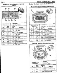
Bottom right is constant 12v. Bottom left is relay ground. Top right is PCM. Top left is the pump circuit.
View attachment 100702
Bottom right is constant 12v. Bottom left is relay ground. Top right is PCM. Top left is the pump circuit.
View attachment 100702
So to measure the resistance through the pump to ground you must measure between the neg battery terminal and the TOP LEFT relay socket in your imagery.