Cranks but won't start

TJBaker57

Lifetime VIP Donor
Member
Aug 16, 2015
3,167
Colorado
That test was done and is documented in a post just before your post. It's just above and with an image. Post #234
Well "My Bad" here.
When I test these things I do so with the relay removed. So a quick glance had me thinking you were connected to the relay socket further up in the picture! I. don't even HAVE a socket there!
 

TJBaker57

Lifetime VIP Donor
Member
Aug 16, 2015
3,167
Colorado
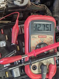
This measurement is between 12v power at the relay, and the pump power supply. Connecting these two wires should start the pump running, but the pump doesn't run.

No, this measurement should really show - 12 volts as the black is hooked to +12 volts and the red is hooked through the fuel pump motor windings to ground.

To run the pump through the meter would require setting up the meter to read DC current (as amps). Many meters have separate test lead connections for 10 amps and are internally fused. Seems every time I do this I then forget to move the test lead back and try to read. voltage somewhere else and instantly blow the internal fuse!

edit:added image PXL_20210611_214019514.jpg
 
Last edited:

coolride

Member
Aug 23, 2019
635
Adirondacks
your "pig tails" might not be as good as you think. Pull the relay and follow the other directions about using "properly size wire" directly into the socket point. What is the measurement?

First thing I did today was attach these pigtails. They're tightly wrapped, I don't think there's a chance they worked loose..
fuelpump42.jpg
 

coolride

Member
Aug 23, 2019
635
Adirondacks
TJBaker57, I wasn't trying to run the pump through the meter. I connected the pigtails on those relay terminals.

I can see how my previous post may have suggested that. I edited that comment to be more clear.
 
Last edited:

coolride

Member
Aug 23, 2019
635
Adirondacks
No, this measurement should really show - 12 volts as the black is hooked to +12 volts and the red is hooked through the fuel pump motor windings to ground.

To run the pump through the meter would require setting up the meter to read DC current (as amps). Many meters have separate test lead connections for 10 amps and are internally fused. Seems every time I do this I then forget to move the test lead back and try to read. voltage somewhere else and instantly blow the internal fuse!

edit:added image View attachment 100703


What resistance reading do you get on the pump circuit?
 

budwich

Member
Jun 16, 2013
2,173
kanata
the test can be done again anywhere along the cabling route IF you can access the wiring somewhere hopefully before the tank / pump... ie. without having to drop the tank. You can use a "pin probe" to poke a hole in the insulation of the wire and thus have access to the point. Do the same resistance test there remember to choose a "good area" for your "ground reference". Depending on the outcome, there are a few other things to try such as running a good piece of wiring from the existing ground point back to a known ground and see if the reading is change... ruling out a grounding issue. Ultimately, it doesn't look good that you are not going to have to get at the pump. Having said that, I am thinking your problem lies with the cabling near the ground... either the wire itself or the bolt point.
 
  • Like
Reactions: coolride

TJBaker57

Lifetime VIP Donor
Member
Aug 16, 2015
3,167
Colorado
I agree with @budwich ... go back and check that G305 ground again. The wiring diagram also calls out a splice point on that ground cable. SP305 I think ((edited:SP306)) . Close by the ground connection. I think those are usually pretty sound but might be worth a look.

How did the harness look when you replaced the pump?

I read about 1 ohm through the pump on mine.
 
Last edited:

TJBaker57

Lifetime VIP Donor
Member
Aug 16, 2015
3,167
Colorado
On the plus side.....

if it is no longer intermittent you stand a far greater chance of finding the trouble instead of chasing ghosts!!
 
  • Like
Reactions: coolride

coolride

Member
Aug 23, 2019
635
Adirondacks
I agree with @budwich ... go back and check that G305 ground again. The wiring diagram also calls out a splice point on that ground cable. SP305 I think ((edited:SP306)) . Close by the ground connection. I think those are usually pretty sound but might be worth a look.

How did the harness look when you replaced the pump?

I read about 1 ohm through the pump on mine.
The harness at the pump looked very good. The wires inside the connector were clean and in nice shape.
 

coolride

Member
Aug 23, 2019
635
Adirondacks
I invite anyone to please watch this video (fast forward to 5:47) and explain how this mechanic removed the fuel pump harness connectors without dropping the tank...

 
Last edited:

mrrsm

Lifetime VIP Donor
Supporting Donor
Member
Oct 22, 2015
8,192
Tampa Bay Area
At 5:59 into that viewing, while rolling the Fuel Pump Connector around in his fingers and eyeballing it with suspicion, the VOP (Video Original Poster) comments to his Viewers:

"This Pump's already been replaced once... Because it's gotta Brand New Connector on it... and it's a Ampro ...or something like that, so it's been done once."

The implication being that HE is NOT the Original Mechanic who apparently replaced the OEM Fuel Pump as the ultimate cause and origin of this Dodgy, Badly Wired Fuel Pump Harness Issue.
 
Last edited:

coolride

Member
Aug 23, 2019
635
Adirondacks
Resistance test of G305 using the neg. bat. terminal as the ground.
fuelpump43.jpg

Piercing the wire at G305 with a needle, and measuring resistance through the crimp.
fuelpump44.jpg
 
Last edited:

mrrsm

Lifetime VIP Donor
Supporting Donor
Member
Oct 22, 2015
8,192
Tampa Bay Area
It looks like that particular Harness may have come with a Harness Extension that had enough Length to allow for the Old Body Harness to reach it and still leave plenty of room adjacent to the Fuel Pump to allow him access to pull it over the Plastic Tank and do his examination and repair. The VOP was also working under a Hydraulic Shop Lift that gave him uncommon access to that area of the Trailblazer

Whatever Brand, Make and Model that Fuel Pump happens to be... it may not have exactly the same Wire Harness Line and Adapters-Connectors that the OEM ACDelco, Delphi or Bosch Fuel Pumps have arranged. As it turned out, IT was indeed where the problem was located. His unique solution was to simply clip off that Bad Harness Connector and directly solder in the wires and apply-heat shrink insulation well enough to by-pass the failed connector.
 

gmcman

Member
Dec 12, 2011
4,660
I went out to the driveway and had a look at G305. The bolt sheared, then was drilled out. All surfaces were sanded clean and I installed a new bolt. After restoration of this ground, the engine didn't start. At least I know the contacts are clean.
View attachment 100644


This was a few days ago, but after you cleaned the contact points, did you verify that this entire lentfh of wire shows continuity?
 

TJBaker57

Lifetime VIP Donor
Member
Aug 16, 2015
3,167
Colorado
I just reviewed the thread and do not see where the fuseblock itself is examined except by the original poster back in 2014.

I myself have experienced fuseblock issues, not with the fuel pump circuit but with the starting circuit. However it is same idea, contact not being made between the relay or fuse and the internal fuseblock wiring.

At this point I would closely examine this possibility and also retest for resistance to ground from the relay socket (top left) that leads to the fuel pump. Try testing not by wiretapping the relay but just poking in the fuseblock socket with something.

Try just stripping back maybe a half inch of that stranded wire you have been using for relay wiretapping and probing in the socket for connection. What I have used is some stranded wire like you have there, stripped back a half inch or so, soldered the stripped portion, then hammered it out flat like a fuse or relay tab. i actually measured it with a caliper but that step may be overkill.
 
  • Like
Reactions: Mooseman

TJBaker57

Lifetime VIP Donor
Member
Aug 16, 2015
3,167
Colorado
Resistance test of G305 using the neg. bat. terminal as the ground.
fuelpump43.jpg
This reply is only to comment that when test results seem to indicate everything is OK but the issue still persists one may need to go deeper.

I like how you probed the wire itself after the first test with the jumper.

I once had an intermittent no crank situation. The day came where I had time available and the no crank occured. Without fiddling with anything I immediately started testing with the meter. At the starter I found a wire connected to a stud. Everything looked clean and tight. The wire eyelet had power. The washer under the wire eyelet had power. The nut holding those two had power. The stud itself,,,,, no power. What!?! Retest, got the same result. Said to myself "Damn! Heard this could happen but never seen it before."

This is why I like that you probed the ground wire itself.

Yesterday I tried unsuccessfully to find some information on where the wire coming out from the fuseblock to fuel pump might be accessed underhood close to the fuseblock. If located that wire could be probed for testing.
 

mrrsm

Lifetime VIP Donor
Supporting Donor
Member
Oct 22, 2015
8,192
Tampa Bay Area
This Video seems to be VERY On Topic, very edifying and useful to this discussion:

 
  • Like
Reactions: TJBaker57

Mooseman

Moderator
Dec 4, 2011
25,996
Ottawa, ON
This one from our alumni @MAY03LT Shows it actually working with the diagram as reference.

 
  • Like
Reactions: mrrsm

TJBaker57

Lifetime VIP Donor
Member
Aug 16, 2015
3,167
Colorado
The trouble is, with an intermittent condition, the very moment you move something, a relay, a fuse, whatever, you have just altered the condition.

This can greatly complicate testing. You pull out a relay and test the socket. You use a jumper to see that the device powered by that relay works. Everything tests OK. When you reinsert the relay,,, if it doesn't work,,, how do you really know all relay terminal tabs have actually made contact in the fuseblock. Same with a fuse. How do you know it makes contact in the circuit.

You have to identify and find the wire(s) leading to or from the fuseblock and probe these.

@coolride you probed your ground wire at G305. Consider locating a place to access the wire headed to the fuel pump and do a similar test with a needle or probe tool. If you're concerned about piercing the insulation, as well you might be, maybe clean the wire well before the piercing and then use some liquid electrical tape afterwards.
 

coolride

Member
Aug 23, 2019
635
Adirondacks
Two strange things happened.

First: I left the ignition in the RUN position over night (somehow I made a dumb mistake :duh:.) By morning the battery had discharged to 3 volts.

I discovered the dead battery ONLY AFTER something else interesting happened.

Second: After watching videos about disassembling the fuse box, I learned that there's smaller blocks of connectors enclosed in the box.

:smile:eyebrowhuh:Then a bell went off.) Back when I was a new owner, I unscrewed these bolts thinking that they would release the fuse box cover (the one that snaps on and off.)

I never re-tightened this bolt (or the others.) This bolt draws the lower connection block tight up against it's contacts. My theory: Over time the lower block of connections that this bolt secures, worked lose, and the fuel pump circuit opened.
fuelpump45.jpg


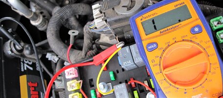
With the bolts re-tightened, I measured 0.4 ohms of resistance to ground through the pump circuit. (fuel pump relay w/pigtails bottom center)
fuelpump46.jpg

Voltage across the relay from constant power to the pump circuit is 12.89 volts. At this point I expected the TB to fire right up,,,and it did. :wowfaint:
fuelpump47.jpg
 
Last edited:

Mooseman

Moderator
Dec 4, 2011
25,996
Ottawa, ON
:celebrate:
 
  • Like
Reactions: mrrsm and coolride

Forum Statistics

Threads
23,664
Posts
641,765
Members
19,091
Latest member
marcinkit

Members Online