
NEED HELP CEL with P0332 rear knock sensor - how to test wire?

trkpony

Member
Joined
Jan 23, 2022
Posts
6
Location
Houston
Hey all,

I have a 2007 GMC Envoy 4.2L I6. It has about 150k miles on it, I bought it in 2010 with about 35k miles on it, I'm the 2nd owner.

TLDR: P0332 won't go away. I changed sensors and plugs. What's the next step for diagnosis?

Recently replaced all the front end suspension and steering components, and changed the oil.

The vehicle has a leaky valve cover gasket and has had it for a long time, so it has always had a bit of a misfire mostly just noticeable at idle, it hasn't ever effected driving conditions. When I checked in the past, I know there was oil leaking onto the spark plugs.

I got a CEL for code P0332. Which by my search, shows a low input on bank 2 (rear) knock sensor. I turned the key on with engine off, KOEO, and checked the voltage with a meter holding one probe on the negative battery terminal and the other probe on the sensor connector and got a voltage reading of 4.052V. I have read it is supposed to have 5V, so I am not sure if this 4.052V would set off the low input reading for the CEL.

1. Is 4.052V too low for the expected voltage reading on the wiring harness connector?

Since I am getting voltage, and I don't know the answer to the above question, I figured the wiring should be good to the connector, so I went ahead and ordered 2 new AC Delco sensors from RockAuto. I replaced them and torqued them to somewhere around 20ft/lbs (My clicky torque wrench starts at 30ft/lbs and so I used the other manual dial/gauge style torque wrench that I have and tried to get it close/above the 18ft/lbs reading)

Reconnected sensors, reset the CEL with the cheap little reader that I have and drove around. The code came back and is the same, P0332. So then I went and swapped the sensors from the front bank to the rear bank to see if the code would shift from P0332 to a different code for the front bank (P0331?) following a bad sensor after the swap.

I should have tried this swap PRIOR to ordering new knock sensors, but I didn't think about it at the time... anyways, the light still came back on and it is the same P0332. So swapping the sensors didn't shift the code to the front bank, so I assume the sensors are good... I have seen a couple videos on testing the sensors, but I wasn't real confident in my results when I tried to test the sensor by itself. All the videos show a slightly different style sensor, like from the v8 motor and I wasn't sure where to test on the 4.2L sensor.

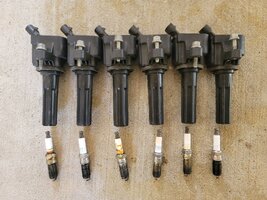
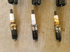
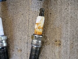
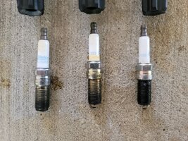
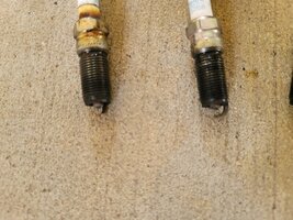
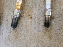
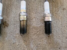
So THEN, I replaced the spark plugs with new plugs. 41-103 AC Delco plugs. When I pulled the old plugs there were a couple that shows oil all the way down their threads. But I haven't ever received a misfire CEL. Also, the cylinder 3 plug had cracked porcelain. I'm not sure how that would happen?

Pictures of spark plugs attached.

I haven't heard any weird popping or pinging noises that I would think I should hear if I have uncontrolled detonation.

What's the best next step for diagnosis? obviously I need to change out valve cover gasket, but should I run a wire from a pin to the knock sensor connector if the 4.052V isn't good enough? How would I do that?

thanks for reading all this and any help
 

Attachments

  • 20260423_130623 (Large).jpg
    20260423_130623 (Large).jpg
    455.4 KB · Views: 3
  • 20260423_130628 (Large).jpg
    20260423_130628 (Large).jpg
    487.2 KB · Views: 4
  • 20260423_130655 (Large).jpg
    20260423_130655 (Large).jpg
    437.6 KB · Views: 3
  • 20260423_130707 (Large).jpg
    20260423_130707 (Large).jpg
    473.9 KB · Views: 3
  • 20260423_130737 (Large).jpg
    20260423_130737 (Large).jpg
    298.6 KB · Views: 3
  • 20260423_130741 (Large).jpg
    20260423_130741 (Large).jpg
    326.7 KB · Views: 2
  • 20260423_130744 (Large).jpg
    20260423_130744 (Large).jpg
    310.8 KB · Views: 3
The oil on the plugs are likely leaking plug well to valve cover gaskets.

Check the block's ground connections for corrosion or poor contact. Remove and clean thoroughly.

Then, get the schematic of the circuit from the manual from either Charm or Lemon and check for proper continuity, no shorts to ground or voltage. Check the connectors for corrosion at both ends. With both the sensor and PCM unplugged, there should be no voltage or short to ground.

Checking a little further, according to this video, there should be very little voltage to the sensors. Not the same vehicle or engine but his diagnostic process is very thorough.


So I'd compare the voltage between the two sensors. If just the one has voltage, this would need to be investigated further. In that case, I would look for damage in the wiring harness for a short to another wire.
 
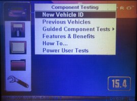
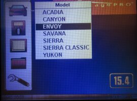
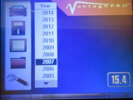
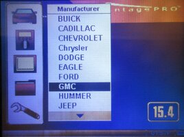
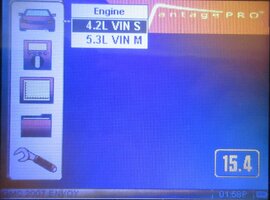
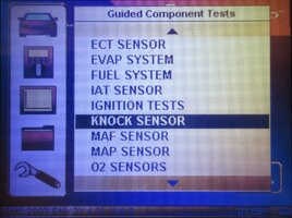
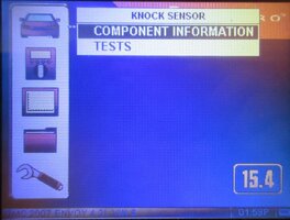
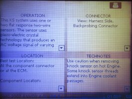
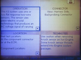
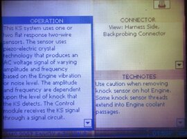
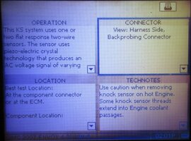
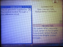
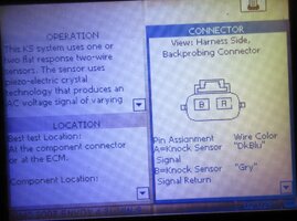
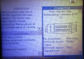
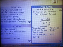
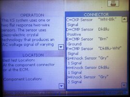
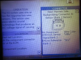
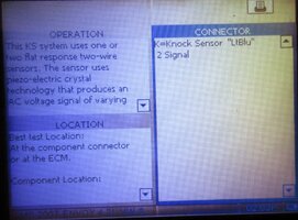
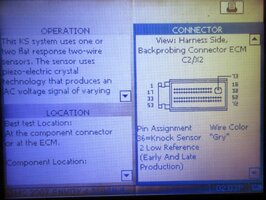
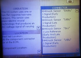
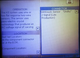
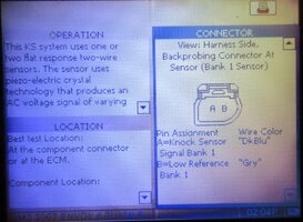
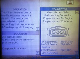
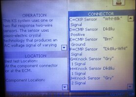
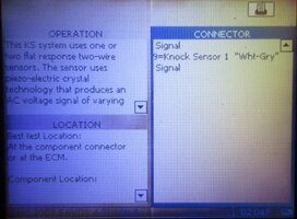
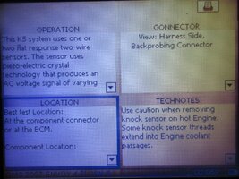
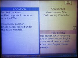
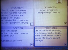
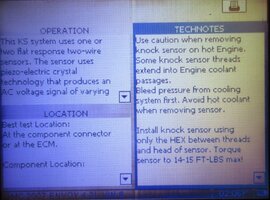
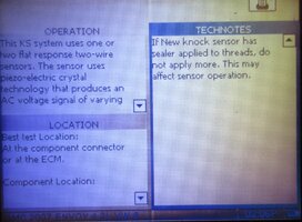
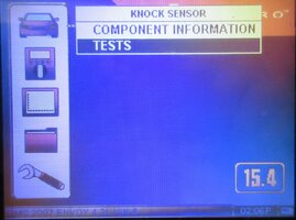
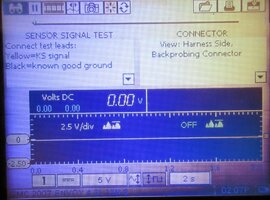
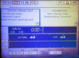
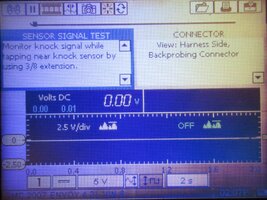
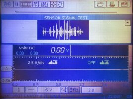
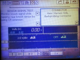
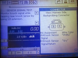
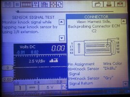
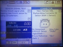
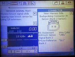
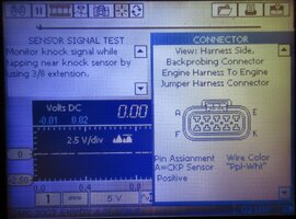
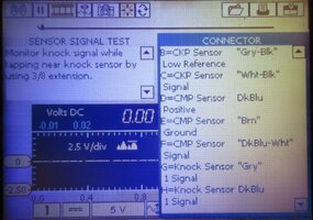
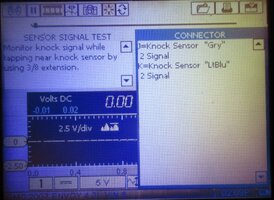
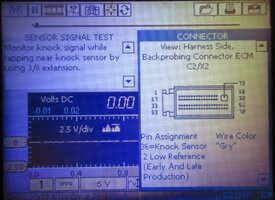
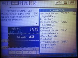
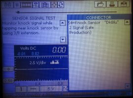
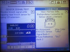
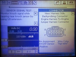
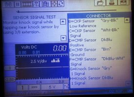
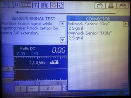
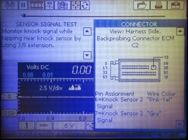
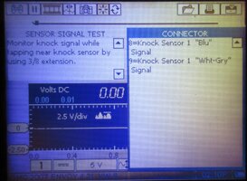
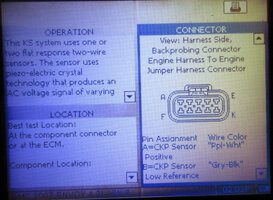
I'm just going to copy-paste the "Intro" from a similar post which explains that by using my Snap-On Vantage Pro Diagnostic Scope that includes "Guided Component Tests"... these 60 images of ALL the Steps involved when doing the KS Diagnostics might "Lift The Stone" off of your chest. These are always technical, non-trivial diagnostics, but without you owning your own unit...THIS procedure is the Next Best Thing for what you need to know:

Welcome to GMT Nation,

Let me know if this appeals to you, but I can plug your 2007 GMC Envoy parameters either into my Snap-On Vantage Pro Graphing Multi-Meter and Scope and check out the KS Diagnostics Steps needed here through the "Guided Component Diagnostics" for your particular SUV and then produce all of the necessary Step By Steps that can be Screen Printed and Posted right back here.... if you think that would help.

Usually, all of these Steps are done with exquisite detail (sort of like Holding The Pro Mechanics Hand) and I have to take a digital picture of what each one looks like on the Scanner screen and then crop, scale and edit them one by one (NEVER a Problem with doing that Task) ...so there are always quite a few images to follow on with... but they will all appear here in groups of 20 images at a time as consecutive Posts that you can then download, save and just use them.

With these images, it will be as though these Snap-On devices were in your own hands while you are standing near the truck, trying to figure out WTF to do next. Other Members will probably chime in with much more direct ideas... but from a purely professional point of view...THESE Machines are very hard to beat for showing What to DO, WHERE to DO it and How to DO it with the RIGHT Diagnostic Tools to use... so they do work very well, too.

The First Batch of 20 of 60 Images Follow On:
 

Attachments

  • IMG_2367.JPG
    IMG_2367.JPG
    382.4 KB · Views: 7
  • IMG_2371.JPG
    IMG_2371.JPG
    331 KB · Views: 6
  • IMG_2370.JPG
    IMG_2370.JPG
    210.5 KB · Views: 5
  • IMG_2369.JPG
    IMG_2369.JPG
    320.7 KB · Views: 6
  • IMG_2372.JPG
    IMG_2372.JPG
    331.8 KB · Views: 5
  • IMG_2373.JPG
    IMG_2373.JPG
    313.5 KB · Views: 5
  • IMG_2374.JPG
    IMG_2374.JPG
    360.5 KB · Views: 5
  • IMG_2375.JPG
    IMG_2375.JPG
    309.3 KB · Views: 7
  • IMG_2376.JPG
    IMG_2376.JPG
    394.3 KB · Views: 6
  • IMG_2377.JPG
    IMG_2377.JPG
    322.5 KB · Views: 6
  • IMG_2378.JPG
    IMG_2378.JPG
    380.1 KB · Views: 6
  • IMG_2380.JPG
    IMG_2380.JPG
    298.4 KB · Views: 6
  • IMG_2379.JPG
    IMG_2379.JPG
    375.8 KB · Views: 6
  • IMG_2381.jpg
    IMG_2381.jpg
    377.8 KB · Views: 6
  • IMG_2382.JPG
    IMG_2382.JPG
    362.5 KB · Views: 6
  • IMG_2383.JPG
    IMG_2383.JPG
    397.4 KB · Views: 5
  • IMG_2384.JPG
    IMG_2384.JPG
    321.1 KB · Views: 4
  • IMG_2387.JPG
    IMG_2387.JPG
    286.6 KB · Views: 6
  • IMG_2386.JPG
    IMG_2386.JPG
    308 KB · Views: 4
  • IMG_2385.JPG
    IMG_2385.JPG
    339.6 KB · Views: 5
Last edited:
Second Batch of 20 Images of 60 Total Images:

IMG_2388.JPGIMG_2389.JPGIMG_2390.JPGIMG_2391.JPGIMG_2392.JPGIMG_2393.JPGIMG_2394.JPGIMG_2395.JPGIMG_2396.JPGIMG_2397.JPGIMG_2398.JPGIMG_2399.JPGIMG_2400.JPGIMG_2401.JPGIMG_2402.JPGIMG_2403.JPGIMG_2404.JPGIMG_2405.JPGIMG_2406.JPGIMG_2408.JPG
 
Last edited:
Last 20 Images of 60 Total Images:

IMG_2409.JPGIMG_2410.JPGIMG_2411.JPGIMG_2412.JPGIMG_2413.JPGIMG_2414.JPGIMG_2415.JPGIMG_2416.JPGIMG_2417.JPGIMG_2418.JPGIMG_2419.JPGIMG_2420.JPGIMG_2421.JPGIMG_2422.JPGIMG_2423.JPGIMG_2424.JPGIMG_2425.JPGIMG_2426.JPGIMG_2427.JPGIMG_2428.JPG

End for all Three Posts.

NOTE: Because the Knock Sensor is classified as a "Piezo-Electric" Device that converts the tympanic engine vibrations and untoward shudders from a flexing speaker-cone like set of motions into Electrical Signals that require an Oscilloscope to be able to sense in very fine details and likewise see the images being created during the Tests above to prove that a New KS is working and that other issues (Broken Wiring) are not involved, feel free to drop in on THIS Link and find out whether or not you would like to get an inexpensive one for this problem and not go broke when doing so:

 
Last edited:
The SM "suggests" a "simple" impedance test of the wiring. Basically, disconnect the sensor. With an ohm meter, measure at the connector, each pin back to a known good ground. The reading should be "OL" (ie. infinity... no continuity)... do the measurement with "key off".

Compare the results for each pin and each sensor. Go from the results.
 
Ok, thanks to you three for the response.
I wanted to give an update because I haven't really had much time to jack with this over the past week.
I watched the video and looked at all the pictures here.
I then disconnected the newly installed sensors and used the multimeter on the ohm setting and checked the sensors.

I can't seem to get any reading on my multimeter from the sensors...

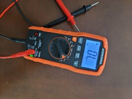
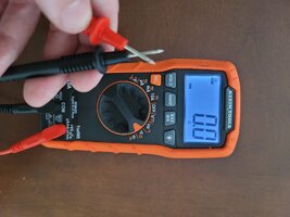
I put it in ohms mode, and selected the auto setting. When the probes are separate, I get OL on the meter. When I put the probes together I get a sound/tone and the meter shows zero 0.00.

I tried to test with both battery cables still connected, and key off engine off. I did not insert the key at all.

There are multiple ground connections on the drivers side of the motor. I tried to hold the black probe directly on the end of the wire spade connectors going to the bolts and also directly on the bolts. Then, I also tried using an alligator clip to connect one black probe to a ground bolt and then each time I tried a different ground bolt. I also held the probe directly on the engine block.

For each ground bolt, I held the other red probe on one pin of the knock sensor to test each pin on the knock sensor... But I'm not getting a reading. I just get OL on the meter. I did this for multiple ground bolts and all 4 pins, 2 on each front and rear knock sensor.
(What are the chances that none of these are good grounds?)

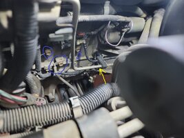
I also did this on the connector and same thing, I get OL. I put the red probe in each of the two pins on the connector separately and held the black probe on the ground bolt and got OL. (I think this is the simple impedance test mentioned above by budwich)

If I grab the end of the red probe I get some readings, I guess it is measuring resistance through my fingers to some other ground location. But I get nothing from the wiring harness connector or the knock sensor pins.

I also tried changing the settings with the auto button on my multimeter, but it doesn't effect the readings. I can change between AUTO, Mohms, Kohm, and just ohm scales.

What am I doing wrong here? Should I disconnect the battery? Should I be connecting both pins on the sensors instead of just 1 at a time?
Do the 4.2L I6 two wire knock sensors work differently than others?
 

Attachments

  • 20260505_094107 (Large).jpg
    20260505_094107 (Large).jpg
    171.9 KB · Views: 1
  • 20260505_094147 (Large).jpg
    20260505_094147 (Large).jpg
    168.1 KB · Views: 1
  • 20260505_094333 (Large) markups.jpg
    20260505_094333 (Large) markups.jpg
    219.7 KB · Views: 1
I also did this on the connector and same thing, I get OL. I put the red probe in each of the two pins on the connector separately and held the black probe on the ground bolt and got OL. (I think this is the simple impedance test mentioned above by budwich)
Yes... that is the "simple test".... its basically used to "thumb check" the system side of things.... looking for some sort of "draw" (less then infinite). Of course, the results don't take into account a broken wire... but I think you did some other tests (voltage measurements) to prove that part.... BUT I see further down in the SM that ~4.2v (to ground) on each sensor is "nominal".... so it appears your earlier voltage measurement might be low... was that measured on both sensors? I guess that should have questioned at the start.... :-)
 
Last edited:
Be sure to check your main ground wire from the battery to the block. When I had my engine mounts changed, when they jacked the engine, the main ground wire was basically just green pus and whatever strands of copper that were left just broke. Do a resistance check between the block and the negative battery post. It should be very low, close to 0.

At this point, if I were you, I'd be checking continuity from the sensor connector to the PCM. The diagnostic aid from the manual also says to check the sensor pins to ground. Should be OL.

 
Yes... that is the "simple test".... its basically used to "thumb check" the system side of things.... looking for some sort of "draw" (less then infinite). Of course, the results don't take into account a broken wire... but I think you did some other tests (voltage measurements) to prove that part.... BUT I see further down in the SM that ~4.2v (to ground) on each sensor is "nominal".... so it appears your earlier voltage measurement might be low... was that measured on both sensors? I guess that should have questioned at the start.... :-)
I just checked both the front sensor and the rear sensor. I turned the key on engine off KOEO, then put meter in DC volts mode, then I put the black probe on the negative battery terminal and red male probe on each of the terminals of the harness side connector, I got readings of around 4.02v, to 4.07v. I then moved the black probe to one of the ground bolts on the engine and same readings. I checked both front and back sensor connectors this time and both gave the same readings, so that isn't different from each sensor either.
 
Be sure to check your main ground wire from the battery to the block. When I had my engine mounts changed, when they jacked the engine, the main ground wire was basically just green pus and whatever strands of copper that were left just broke. Do a resistance check between the block and the negative battery post. It should be very low, close to 0.

At this point, if I were you, I'd be checking continuity from the sensor connector to the PCM. The diagnostic aid from the manual also says to check the sensor pins to ground. Should be OL.

thank you for the direct link to the Lemon manual, I see why you said to check it in your first post, walks you through each step pretty clearly.
So Step 1/2 is check for engine noise or diagnostic proceedure. I know my valve cover gasket leaks oil on the plugs, which is causing a misfire and could ultimately be causing this knocking too, so I need to fix that. But I don't hear any noise so I'm skipping this step for now.
Step 3, as you mentioned is checking the sensor pin to ground, which is what I did above and its reading OL. which appears to be good, I thought I was doing something wrong getting the OL reading.

I'll go try the next steps and report back. thanks again.
 
I just checked both the front sensor and the rear sensor. I turned the key on engine off KOEO, then put meter in DC volts mode, then I put the black probe on the negative battery terminal and red male probe on each of the terminals of the harness side connector, I got readings of around 4.02v, to 4.07v. I then moved the black probe to one of the ground bolts on the engine and same readings. I checked both front and back sensor connectors this time and both gave the same readings, so that isn't different from each sensor either.
Now you getting into the "dirt".... both readings are "too conveniently low".... yet only one "complains". Its quite possible that your meter / leads might be "uncalibrated" such that a "small error" results (ie. the measure is actually close enough to the expected 4.2v.). Note: this value does not actually provide any direct contribution to the resulting code although perhaps if it was significantly low such 2-3v then maybe. The code appears to be set from more of a "ac signal RMS" type value. Hence, the sensor vibration frequency AND amplitude are important.

ADDED: did you measure the voltage on BOTH pins at the connector? OOPS.... I misread the SM... the 4.2v is the upper limit. The voltage reading should be below that value... which yours are.


At this point, without getting some sort of signal scope, it might be tough to find the issue... perhaps pointing to the PCM. Bringing you to the PCM... have you pulled the connector and looked at the condition of the pins in the connectors.... focusing on those associated with the sensors? Its possible that the have oxidized enough to cause a "base voltage issue" (ie. slightly lower sensor "bias").

NOTE: probing any pins in a connector is dangerous to the pin itself IF you don't use the appropriate size probe. Too large a probe may cause damage such that the connections thereafter are NOT very good in future operation.

ADDED: another test suggested in the SM is a "active test". disconnect the sensor in question. Carefully connect your meter with the sensor wire (ie. rig up some form of "T"). Set the meter on ac volts. Set the key ON ENG OFF. Get a reading... probably nothing... wait for it settle. Then get a non-metal "striker" and tap on the engine block near the area of the sensor. Monitor the meter, you should see some change in voltage showing up as the sensor "causes AC" to occur (basically modulating the dc signal... that 4.2v DC... I think).
 
Last edited:
  • Like
Reactions: Mooseman
A little update on this since its been multiple weeks... Problem still not fixed.

I decided to go ahead and change out the valve cover gasket, just to try to eliminate the possibility of the oil leaking on the plugs, causing a misfire, and the chance that I am actually getting engine knocking and just dont realize it.
It all went well, I took it apart, replaced the valve cover gasket and the intake manifold gaskets. I also replaced the thermostat while it was opened up a bit, because it is much easier to access the thermostat with the ECM, alternator, and upper intake removed. I also cleaned off the plugs, cleaned out the throttle body and the upper intake while I had them off.
I reconnected everything and it runs nice and smooth now at idle. I used to have a slight misfire and a little rough hiccupping at idle that I assumed to be the spark plugs with oil on them not firing smoothly, but not rough enough to set off a misfire CEL. At first glance, it appears that may have been the culprit or something on the intake/throttle body side that I cleaned while doing the valve cover gasket. Will have to continue to monitor this and see if the rough idle returns.

But for now, I did a test drive and sure enough, the CEL came back for the P0332 for the rear knock sensor. So I think I need to follow the suggestions and look at the wire or connector back to the PCM.

At this point, without getting some sort of signal scope, it might be tough to find the issue... perhaps pointing to the PCM. Bringing you to the PCM... have you pulled the connector and looked at the condition of the pins in the connectors.... focusing on those associated with the sensors? Its possible that the have oxidized enough to cause a "base voltage issue" (ie. slightly lower sensor "bias").

NOTE: probing any pins in a connector is dangerous to the pin itself IF you don't use the appropriate size probe. Too large a probe may cause damage such that the connections thereafter are NOT very good in future operation.
This is my next move. I will rewatch the video above and the info provided and find which connector the wiring for the knock sensor goes to in the PCM and I will need to buy a set of small connector probes to be able to probe that connection pin at the PCM connector side of the wiring to do the continuity test to the knock sensor connector pin.

Thanks again for the suggestions and help. I'll update after I test the PCM to knock sensor connector wires.
 
  • Like
Reactions: Mooseman
EDIT:

A Correction and Admission of Error needs adding ahead of this Post. Thanks to the follow on Posts by @budwich and @Mooseman after this one which informs My Mistake in the idea that the Knock Sensor is not the Fault. All of the other information is valid and worth knowing, however not factored into this Diagnostic. Thank Goodness for the "Hive Mind" at GMT Nation keeping me in line... Thank You, Gentleman!


I've been puzzling over this Thread over how much the focus of your investigation has been over the One Device that actually seems to have been functioning correctly by its very design as a *Warning* that the P-0332 Code indicates ... meaning that it is actually WORKING and perhaps to just just "Take It's Word For It..." that there is Neither a problem with the Knock Sensor... Nor with the Wiring in between the Sensor and PCM... It is just emphasizing that the actual root cause of this problem has yet to be discovered.

The P-0332 Code is not a cause... but an effect that perhaps has a less obvious Point of Origin in either one or more Coil On Plug Ignition Coils...and drilling down even further... the principle of "Shorting To Ground" outside of the Cylinder Interior where you would expect the Spark Plug Electrode Ignition Plasma to fire if the atmospheric (Air to Fuel Balance of 14.7 to 1 ) should occur... --== but which will become impossible to achieve if those conditions become TOO LEAN ==-- due perhaps to failing EFIs properly spraying Atomized Fuel versus Fuel Droplets that are incapable of burning due their inability to Mix with NA Inhalations... or due to Weakened or Failing EFI Coil Windings.

It will not be within most of our repair experiences and conventional thinking to realize that several dreadful things will follow on that can cause internal cylinder conditions to happen that WILL cause Pre-Ignition and Mis-Fires to happen.... involving Super-Stressed Coil On Plug Secondary Ignition Events climbing to ridiculously HIGH KV Levels because there are simply not enough Hydro-Carbon Molecules vs Available O2 to allow an Electrical Spark to propagate INSIDE of the Cylinder(s) as the Spark Plugs TRY to Fire... Just BTDC.

It is this NEXT Part that I draw your attention to the fact that all during such LEAN IN-CYLINDER IGNITION EVENTS, the Extra High KV will oscillate back and forth between the Secondary, slamming back into the Primary Side of the COP(s) and since "Electricity ALWAYS seeks the Easiest Path to GROUND" ... the Residual Electrical HIGH KV will seek to GROUND itself along the OUTSIDE of the Cylinder and follow the Interior Rubber Insulator Boot(s) and along the exterior of the Porcelain Insulator(s) of the Spark-Plug(s) and find their ultimate ways to GROUND OUT in the Outer Aluminum Engine Head.

Lean In-Cylinder Conditions eventually DESTROY COPs.

Whenever this Phenomena develops, Portions of the Rubber Insulator Boot(s) are -=BURNED=- by the HIGH KV Electrical Plasma Arcing and this creates CARBON TRACES (Tracks) inside and those are Channels that can leave Electrically Conductive Carbon Tracings along the exterior of the Spark Plug(s) as well that will make consecutive Mis-Fires easier and easier to achieve more consistently over time OUTSIDE THE CYLINDER. These Images illustrate what to LOOK for if you suspect these conditions are the prevailing cause of the Knock Sensor Issue:

spark-plugs.jpgimage_E_6.jpg
https://www.tomorrowstechnician.com/ignition-and-coil-flashover/

https://easyautodiagnostics.com/chrysler/2000-2400/carbon-tracks-misfire?start=2

https://easyautodiagnostics.com/misc-index/two-wire-cop-coil-tests

PS:

Excessive In-Cylinder Carbon "MUNG" Deposits of the Piston Tops and around the Valve Seats can increase the *Compression Quench* sufficient enough to cause Pre-Ignition as well. Ergo, Carbon Busting Treatment could improve this condition with a Non-Mechanical Repair Intervention using Carbon Busting Liquid Solvent Treatments.

See THESE Threads for the "How To" Procedures and Empirical Success Stories:


Last edited:
I've been puzzling over this Thread over how much the focus of your investigation has been over the One Device that actually seems to have been functioning correctly by its very design as a *Warning* that the P-0332 Code indicates ... meaning that it is actually WORKING and perhaps to just just "Take It's Word For It..." that there is Neither a problem with the Knock Sensor... Nor with the Wiring in between the Sensor and PCM... It is just emphasizing that the actual root cause of this problem has yet to be discovered.

The P-0332 Code is not a cause... but an effect that perhaps has a less obvious Point of Origin in either one or more Coil On Plug Ignition Coils...and drilling down even further... the principle of "Shorting To Ground" outside of the Cylinder Interior where you would expect the Spark Plug Electrode Ignition Plasma to fire if the atmospheric (Air to Fuel Balance of 14.7 to 1 ) should occur... --== but which will become impossible to achieve if those conditions become TOO LEAN ==-- due perhaps to failing EFIs properly spraying Atomized Fuel versus Fuel Droplets that are incapable of burning due their inability to Mix with NA Inhalations... or due to Weakened or Failing EFI Coil Windings.

It will not be within most of our repair experiences and conventional thinking to realize that several dreadful things will follow on that can cause internal cylinder conditions to happen that WILL cause Pre-Ignition and Mis-Fires to happen.... involving Super-Stressed Coil On Plug Secondary Ignition Events climbing to ridiculously HIGH KV Levels because there are simply not enough Hydro-Carbon Molecules vs Available O2 to allow an Electrical Spark to propagate INSIDE of the Cylinder(s) as the Spark Plugs TRY to Fire... Just BTDC.

It is this NEXT Part that I draw your attention to the fact that all during such LEAN IN-CYLINDER IGNITION EVENTS, the Extra High KV will oscillate back and forth between the Secondary, slamming back into the Primary Side of the COP(s) and since "Electricity ALWAYS seeks the Easiest Path to GROUND" ... the Residual Electrical HIGH KV will seek to GROUND itself along the OUTSIDE of the Cylinder and follow the Interior Rubber Insulator Boot(s) and along the exterior of the Porcelain Insulator(s) of the Spark-Plug(s) and find their ultimate ways to GROUND OUT in the Outer Aluminum Engine Head.

Lean In-Cylinder Conditions eventually DESTROY COPs.

Whenever this Phenomena develops, Portions of the Rubber Insulator Boot(s) are -=BURNED=- by the HIGH KV Electrical Plasma Arcing and this creates CARBON TRACES (Tracks) inside and those are Channels that can leave Electrically Conductive Carbon Tracings along the exterior of the Spark Plug(s) as well that will make consecutive Mis-Fires easier and easier to achieve more consistently over time OUTSIDE THE CYLINDER. These Images illustrate what to LOOK for if you suspect these conditions are the prevailing cause of the Knock Sensor Issue:

View attachment 119604View attachment 119605
https://www.tomorrowstechnician.com/ignition-and-coil-flashover/

https://easyautodiagnostics.com/chrysler/2000-2400/carbon-tracks-misfire?start=2

https://easyautodiagnostics.com/misc-index/two-wire-cop-coil-tests

PS:

Excessive In-Cylinder Carbon "MUNG" Deposits of the Piston Tops and around the Valve Seats can increase the *Compression Quench* sufficient enough to cause Pre-Ignition as well. Ergo, Carbon Busting Treatment could improve this condition with a Non-Mechanical Repair Intervention using Carbon Busting Liquid Solvent Treatments.

See THESE Threads for the "How To" Procedures and Empirical Success Stories:


thanks for those links.
You hit the nail on the head here, "root cause... yet to be discovered"

I installed new spark plugs during this operation, so probably not a spark plug issue.
Could be the COPs, they have 50k plus miles on them. I don't remember when I replaced the coils last. I'll check out the testing on the COP too.
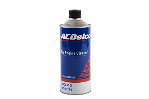
Top end cleaner will be another next step to see if cleaning up those cylinders will fix any potential knocks that may actually be occuring if the wiring tests good.
thanks.
 
Here's the schematic for the knock sensors. You'll want to check the wires for sensor #2.

Screenshot 2026-05-25 120248.png

Be sure to check resistance/continuity from the sensor wires to the PCM and also to ground on both wires at both ends.

Since you've tried swapping and replacing the sensors, and if all these wiring checks are good and the PCM connector pins are clean, I would be suspecting the PCM itself has gone bad. It might be supplying the correct 4V reference but the sensing circuit in the PCM might not be picking it up correctly. To be absolutely sure about this, you would need a means of scanning live data, look at sensor 1 and 2 data and tap on the block next to them to see if it picks up the knock and are comparable to each other.
 
  • Like
Reactions: mrrsm and budwich
I've been puzzling over this Thread over how much the focus of your investigation has been over the One Device that actually seems to have been functioning correctly by its very design as a *Warning* that the P-0332 Code indicates ... meaning that it is actually WORKING and perhaps to just just "Take It's Word For It..." that there is Neither a problem with the Knock Sensor... Nor with the Wiring in between the Sensor and PCM... It is just emphasizing that the actual root cause of this problem has yet to be discovered.
Actually, I think this code (and related sister code) means that the system will not being doing its job as the system disregards the output from the sensor and thus there is NO compensation done in the system for timing adjustments (and other running adjustments) to prevent "knock". Ultimately, perhaps "engine dangerous" if this persists depending on the severity.
 
  • Like
Reactions: Mooseman

Forum Statistics

Threads
24,285
Posts
648,841
Members
20,777
Latest member
eversond1

Members Online