Hey all,
I have a 2007 GMC Envoy 4.2L I6. It has about 150k miles on it, I bought it in 2010 with about 35k miles on it, I'm the 2nd owner.
TLDR: P0332 won't go away. I changed sensors and plugs. What's the next step for diagnosis?
Recently replaced all the front end suspension and steering components, and changed the oil.
The vehicle has a leaky valve cover gasket and has had it for a long time, so it has always had a bit of a misfire mostly just noticeable at idle, it hasn't ever effected driving conditions. When I checked in the past, I know there was oil leaking onto the spark plugs.
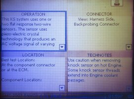
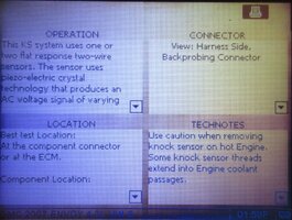
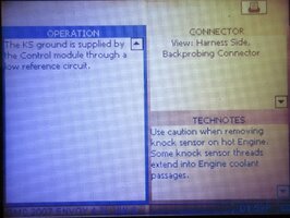
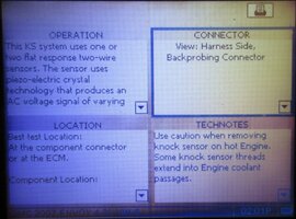
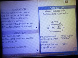
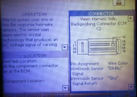
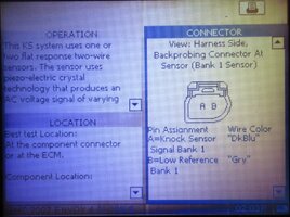
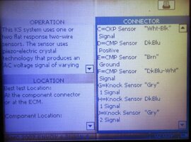
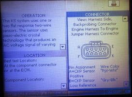
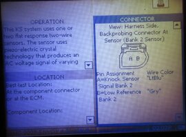
I got a CEL for code P0332. Which by my search, shows a low input on bank 2 (rear) knock sensor. I turned the key on with engine off, KOEO, and checked the voltage with a meter holding one probe on the negative battery terminal and the other probe on the sensor connector and got a voltage reading of 4.052V. I have read it is supposed to have 5V, so I am not sure if this 4.052V would set off the low input reading for the CEL.
1. Is 4.052V too low for the expected voltage reading on the wiring harness connector?
Since I am getting voltage, and I don't know the answer to the above question, I figured the wiring should be good to the connector, so I went ahead and ordered 2 new AC Delco sensors from RockAuto. I replaced them and torqued them to somewhere around 20ft/lbs (My clicky torque wrench starts at 30ft/lbs and so I used the other manual dial/gauge style torque wrench that I have and tried to get it close/above the 18ft/lbs reading)
Reconnected sensors, reset the CEL with the cheap little reader that I have and drove around. The code came back and is the same, P0332. So then I went and swapped the sensors from the front bank to the rear bank to see if the code would shift from P0332 to a different code for the front bank (P0331?) following a bad sensor after the swap.
I should have tried this swap PRIOR to ordering new knock sensors, but I didn't think about it at the time... anyways, the light still came back on and it is the same P0332. So swapping the sensors didn't shift the code to the front bank, so I assume the sensors are good... I have seen a couple videos on testing the sensors, but I wasn't real confident in my results when I tried to test the sensor by itself. All the videos show a slightly different style sensor, like from the v8 motor and I wasn't sure where to test on the 4.2L sensor.
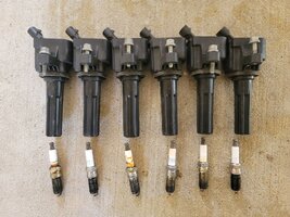
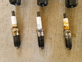
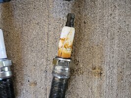
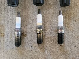
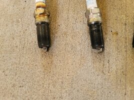
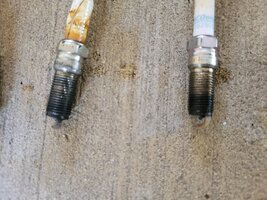
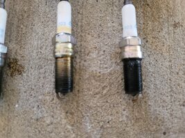
So THEN, I replaced the spark plugs with new plugs. 41-103 AC Delco plugs. When I pulled the old plugs there were a couple that shows oil all the way down their threads. But I haven't ever received a misfire CEL. Also, the cylinder 3 plug had cracked porcelain. I'm not sure how that would happen?
Pictures of spark plugs attached.
I haven't heard any weird popping or pinging noises that I would think I should hear if I have uncontrolled detonation.
What's the best next step for diagnosis? obviously I need to change out valve cover gasket, but should I run a wire from a pin to the knock sensor connector if the 4.052V isn't good enough? How would I do that?
thanks for reading all this and any help
I have a 2007 GMC Envoy 4.2L I6. It has about 150k miles on it, I bought it in 2010 with about 35k miles on it, I'm the 2nd owner.
TLDR: P0332 won't go away. I changed sensors and plugs. What's the next step for diagnosis?
Recently replaced all the front end suspension and steering components, and changed the oil.
The vehicle has a leaky valve cover gasket and has had it for a long time, so it has always had a bit of a misfire mostly just noticeable at idle, it hasn't ever effected driving conditions. When I checked in the past, I know there was oil leaking onto the spark plugs.
I got a CEL for code P0332. Which by my search, shows a low input on bank 2 (rear) knock sensor. I turned the key on with engine off, KOEO, and checked the voltage with a meter holding one probe on the negative battery terminal and the other probe on the sensor connector and got a voltage reading of 4.052V. I have read it is supposed to have 5V, so I am not sure if this 4.052V would set off the low input reading for the CEL.
1. Is 4.052V too low for the expected voltage reading on the wiring harness connector?
Since I am getting voltage, and I don't know the answer to the above question, I figured the wiring should be good to the connector, so I went ahead and ordered 2 new AC Delco sensors from RockAuto. I replaced them and torqued them to somewhere around 20ft/lbs (My clicky torque wrench starts at 30ft/lbs and so I used the other manual dial/gauge style torque wrench that I have and tried to get it close/above the 18ft/lbs reading)
Reconnected sensors, reset the CEL with the cheap little reader that I have and drove around. The code came back and is the same, P0332. So then I went and swapped the sensors from the front bank to the rear bank to see if the code would shift from P0332 to a different code for the front bank (P0331?) following a bad sensor after the swap.
I should have tried this swap PRIOR to ordering new knock sensors, but I didn't think about it at the time... anyways, the light still came back on and it is the same P0332. So swapping the sensors didn't shift the code to the front bank, so I assume the sensors are good... I have seen a couple videos on testing the sensors, but I wasn't real confident in my results when I tried to test the sensor by itself. All the videos show a slightly different style sensor, like from the v8 motor and I wasn't sure where to test on the 4.2L sensor.
So THEN, I replaced the spark plugs with new plugs. 41-103 AC Delco plugs. When I pulled the old plugs there were a couple that shows oil all the way down their threads. But I haven't ever received a misfire CEL. Also, the cylinder 3 plug had cracked porcelain. I'm not sure how that would happen?
Pictures of spark plugs attached.
I haven't heard any weird popping or pinging noises that I would think I should hear if I have uncontrolled detonation.
What's the best next step for diagnosis? obviously I need to change out valve cover gasket, but should I run a wire from a pin to the knock sensor connector if the 4.052V isn't good enough? How would I do that?
thanks for reading all this and any help
Attachments
-
 20260423_130623 (Large).jpg455.4 KB · Views: 1
 -
 20260423_130628 (Large).jpg487.2 KB · Views: 2
 -
 20260423_130655 (Large).jpg437.6 KB · Views: 1
 -
 20260423_130707 (Large).jpg473.9 KB · Views: 1
 -
 20260423_130737 (Large).jpg298.6 KB · Views: 1
 -
 20260423_130741 (Large).jpg326.7 KB · Views: 1
 -
 20260423_130744 (Large).jpg310.8 KB · Views: 2