How To Use PICO #2204A & HANTEK #1008C Oscilloscopes

mrrsm

Original poster
Lifetime VIP Donor
Supporting Donor
Member
Oct 22, 2015
8,246
Tampa Bay Area
You don't need a Huge Bag of Coins in order to obtain and use an Oscilloscope for performing In-Depth Wave Form Analysis in Automotive Applications on everything from Problematic Electronic Fuel Injection to obtaining accurate Compression Tests to Diagnose Internal Engine Conditions.

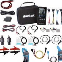
HANTEK makes (...and Amazon, eBay and OTHER Outlets sells) ALL of the discreet equipment components necessary to accurately conduct these types of Automotive Diagnostics ... and all can obtained on a Very Modest Budget.

The Basic Oscilloscope Hardware is listed below:

(1) Windows Laptop (...or Tablet with the Windows OS Variant)
RCAWINDOWSTABLET.jpg

How to Set Up the Hantek 1008 Hantek Software and Windows Drivers on your Laptop or Tablet:


(2) Hantek 1008 (or later 1008-C Variant) USB Powered 8 Channel Oscilloscope
HANTEKOSCILLOSCOPE1.jpgHANTEKLOWAMPROBE2.jpg

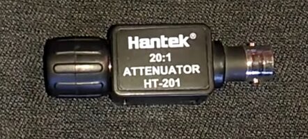
(3) Hantek 20-1 Signal Attenuator
HANTEK20TO1ATTENUATOR.jpg
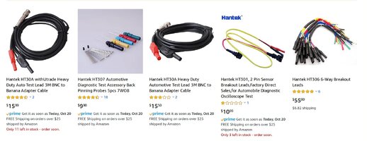
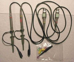
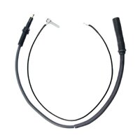
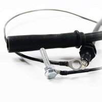
(4) Hantek BNC and Adaptive Leads
HANTEKLEADS.jpg

(5) Hantek Model # CC-650 High AC-DC Voltage-Amperage Clamp
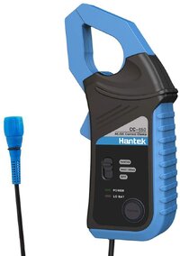
HANTEKLOWAMPROBE1.jpg
(6) Hantek Model # CC-65 Low AC/DC Voltage-Amperage Clamp
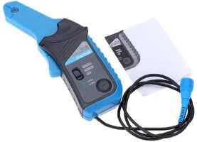
HANTEKLOWAMPROBE3.jpg

... and some necessary "Oscilloscope: 101" Basic Instructions on How To Use ALL of this Equipment:

The attached Video covers the How to Set up the Hantek 1008 Oscilloscope for the purpose of Testing the Internal Wave Form - Voltage Behavior of EFIs in Very Great Detail:


Here is the same VOP (Video Original Poster) using the same Set Up...but employing the Hantek CC-650 High Amperage Probe to perform a Relative Compression Test on a GMC Envoy Atlas 4.2L Engine (after a P0305 Code). THIS Technique shows the Value of a RAPID, Non-Invasive Diagnosis for Compression:


...and again... for Testing the Alternator using the High Current CC-650 Amp Clamp:


WARNING: PLEASE DO NOT USE YOUR HANTEK 1008(A-C VARIANTS) TO CHECK THE AC VOLTAGE IN YOUR HOME or on a Stand-Alone AC or DC Generator (120 VAC AT 60 CPS @ 15-20 Amps). The VOP Explains WHY This would be Very Dangerous!

 
Last edited:

mrrsm

Original poster
Lifetime VIP Donor
Supporting Donor
Member
Oct 22, 2015
8,246
Tampa Bay Area
While this next Video features one of our Brothers Across The Pond in England...who is using a much more expensive PICO Scope for this Diagnosis of a Possible Failing Fuel Pump... the Principles involved will STILL apply when using the Hantek Oscilloscope.

It is important to note that these kinds of Tests are remarkably free of having to "Get Dirty and Tear into Things" and can help all Mechanics to better visualize what is actually happening INSIDE OF THE PUMP...INSIDE OF THE FUEL TANK. Therefore... it will provide a definitive diagnosis that you can remain confident in... rather than just replacing the Fuel Pump out of hand ... on a Guess:


mrrsm

Original poster
Lifetime VIP Donor
Supporting Donor
Member
Oct 22, 2015
8,246
Tampa Bay Area
These two videos drew recent Member Interest from @freddyboy61 and @Maverick6587

https://gmtnation.com/forums/threads/two-videos-covering-good-info-on-o2-sensor-diagnostics.20446/

In order to assist anyone curious about using this Hantek Oscilloscope Equipment for Advanced Automotive Diagnostics… I’ve Photo-Documented the Un-Boxing of ALL of the required equipment which is available as the separate, Original Hantek Model #1008C Kit along with other separate items available for purchase on Amazon at very reasonable prices.

This unique Hantek Equipment is a Damned Sight Less Expensive than the PICO Professional Automotive Diagnostic Oscilloscope Kit. Here is a link to (43) Close Up Images, which includes discreet Hantek OEM Instructions for the two High and Low Amperage Clamps describing their unique set ups and applications for Automotive Wave Form Diagnostics:

https://www.flickr.com/photos/126111508@N07/albums/72157711615754381
 

mrrsm

Original poster
Lifetime VIP Donor
Supporting Donor
Member
Oct 22, 2015
8,246
Tampa Bay Area
If you have any of the Later Model GM Trucks-Suvs and/or Passenger Vehicles that use HVAC Controllers employing Pulse Width Modulation (PWM) instead of The Old and (...mostly...) Reliable Resistor Pack(s) to Modulate the Cabin Fan Blower Motor Speed... THIS Video shows how to easily Diagnose what will otherwise be 'Invisible' to you as a Graphed Electronic PWM Voltage Signal using the Hantek Model #1008C Oscilloscope and a Hantek Model # CC-65 'Low Amperage' Amp Clamp.

Knowing what a "Good Wave Form" looks like, as in this particular example involving a GM Corvette application, will help you to discern any non-obvious failures in the least intrusive manner possible and with the lowest 'Sweat Equity'. This thing can also reduce the need for unnecessary Parts Swapping that may occur when trying to figure things out. This is yet another Automotive Application that demonstrates the value of conducting deeper diagnostics with Good Equipment... and NOT Going Broke by investing in this Gear. In the long run, if Time is Money... having the Hantek 1008C Kit will save you BOTH of these important commodities:

 
Last edited:

mrrsm

Original poster
Lifetime VIP Donor
Supporting Donor
Member
Oct 22, 2015
8,246
Tampa Bay Area
I've made quite a few references of late encouraging the use of the Hantek Model #1008C 8-Channel Oscilloscope in conjunction with 20:1 Attenuator and an Amperage Clamp to help broaden our Automotive Diagnostic Regimen Horizons in an inexpensive way. But the problem with isolating down to even one incident where the use of this equipment CAN definitively Identify and Solve even the most intractable of Automotive Function and Performance issues always raises the Barrier caused by a lack of understanding of, "Just Exactly... How Do These Oscilloscopes Work?"

So a few weeks back, I began searching the 'Net for any "Official Automotive Oscilloscope Training Manuals" that would include Specific Wave Form Analyses and discovered that other than Highly Technical Electronic Component Repair Service Manuals and Books that have been Out Of Print since the 1960s to 1970s... ONLY THREE Dedicated Books are presently available on line for purchase:

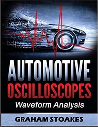
(1) Automotive Oscilloscopes Wave Form Analysis by Graham Stoakes

Available on Amazon for around $45.00:


AUTOSCILLOSCOPEBOOKS1.jpgAUTOSCILLOSCOPEBOOKS2.jpg

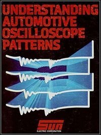
(2) Understanding Automotive Oscilloscope Patterns by SUN Electric Corporation

Available on Amazon for around $46.00:

NOTE: THIS Book is useful ONLY for HEI and Primitive and Basic Distributor-Points Based Automotive Ignition Systems for GM, Ford and Chrysler Applications (Published in 1982). It Does NOT Address ANY Modern PCM-ECM EFI Automotive Applications.


AUTOSCILLOSCOPEBOOKS3.jpg

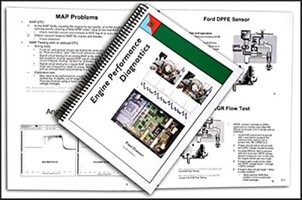
(3) Engine Performance Diagnostics by Paul "Scanner" Danner:

Available on Amazon for around $110.00:


AUTOSCILLOSCOPEBOOKS4.jpg

I obtained Graham Stoakes Book (Item #1) and discovered that all aspects of this topic cannot be explained in a more straightforward way than his displays and methods of instructions that are within this Book. It not only provides innumerable Wave Form Exemplars for just about anything you can think of for both Modern ECM-PCM Contolled Gasoline AND Diesel Engines... but it Graphically Numbers and Explains each and every subtle nuance of each and every Unique Scoped Wave Form to help the Mechanic to better understand what they should be looking for in each and every Auto Electronic Diagnostic situation.

So besides my being a predominantly "Visual Learner" via the study of Youtube Videos about the Hantek AND PICO Devices offered online by "Scanner Danner" and others, I've discovered by careful reading that these books will prove to be great compliments to the available "Video knowledge" in the proper use and interpretation of Automotive Diagnostic Oscilloscope Wave Forms.

By the way... the SUN Electric Corporation is "The Biggest Grand-Daddy of them ALL" when it came to producing the Original, Roll-Around HUGE Red Colored SUN Automotive Diagnostic Scanners used in Dealerships going as far back as the 1980s.
 
Last edited:

mrrsm

Original poster
Lifetime VIP Donor
Supporting Donor
Member
Oct 22, 2015
8,246
Tampa Bay Area
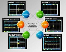
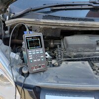
So if you are among those of us lucky enough to Own and Rely upon the “GYMKO” Tech 2 Hand Hand Scanner and like the feeling of having that “Useful GM Diagnostic Brick” in their hands… then YOU are the Target Audience for THIS Amazing Hantek Model #2D82 Multi-Function Automotive Oscilloscope and Diagnostic Tool Combo that sports the following Features:

An Automotive Diagnostic Tool (With Built-In Sensor Pre-Sets)
An Oscilloscope (2 Channel)
A Signal Source Generator
A Multi-Meter

81oHAiYt2LL._SL1500_.jpg91493sHMuGL._SL1500_.jpg71F+W1gtkSL._SL1500_.jpg51TJ2GoOKML.jpg81TScbLi8SL._SL1270_.jpgHANTEKNEWORDER.jpg


THIS Device is for You if YOU are interested in performing Serious Automotive Diagnostics capable of ALSO investigating and diagnosing ALL Electrical Automotive Systems behavior and Class 2 Modules performance ON A HAND-HELD OSCILLOSCOPE using “Voltage Over Time” and Known Wave Forms to avoid having to perform unnecessary, laborious and expensive repairs Based upon a “Best Guess Approach”. I am especially enamored of using Oscilloscopes for Automotive Diagnostics… But I’ll be the First to Admit that I HATE  having to:

Set Up the Laptop or the Tablet ...and find a Safe Perch for it...
Set Up either a Hantek or PICO Scope...and find a Safe Perch for it...
Set Up a Decent Multi-Meter …while Juggling IT and Everything Else, TOO...
And THEN having to Arrange all of the BNC Cabling and Sensor Wiring around Running Vehicles.

What a Serious PITA! But THIS Little Hantek Beauty collects and consolidates ALL of these Functions into a “Single Brick” that sports familiar Function Keys, Up and Down Arrow Buttons and Press Button Selections to Navigate and Select all of its many Features and make Rapid on-screen Adjustments to get the Views arranged properly. Ordinarily, you would have to pay around $1,000.00 or MUCH More for the High End Scopes that include the Additional Tools to do all of these Jobs.

But Please … Work with me here as these Videos have been done by people with serious “Accent and Pronunciation Issues” in offering their English Speaking Observations and Instructions. And yet, they will still provide Good Un-Boxing Imagery and Live Use Exemplars demonstrating the capabilities of this Device.


For the High-Features Kit WITH Both Amp Clamps and the Complete Kit Gear 1-2-(3) for $380.00:

https://www.amazon.com/dp/B084TMDZJC/?tag=gmtnation-20

For the Mid-Features Kit Without Amp Clamps… This is the 1-(2)-3 version for $280.00:

https://www.amazon.com/dp/B084TM123B/?tag=gmtnation-20

...and for a Low-Features Kit (Single Line Filter) Budget Buy ... This is the (1)-2-3 Version:

https://www.amazon.com/dp/B084TM8HZQ/?tag=gmtnation-20

...and for the Other, PREVIOUS Low Budget Model(s) of the HANTEK #2D72 Unit for $180.00:

https://www.amazon.com/Hantek2D72-Oscilloscope-Generator-Multimeter-Multifunction/dp/B07PWZTNJK/ref=as_li_ss_tl?_encoding=UTF8&pd_rd_i=B07PWZTNJK&pd_rd_r=8YAPWKN7KD9ENWJW0X08&pd_rd_w=6s0Mc&pd_rd_wg=kPdzl&pf_rd_p=2d1fd857-8ce8-4666-a498-9c484c5098db&pf_rd_r=8YAPWKN7KD9ENWJW0X08&refRID=8YAPWKN7KD9ENWJW0X08&linkCode=sl1&tag=linkid19-20&
linkId=2945cc19a225b93ee183af9323bc2fa8&language=en_US&th=1


Since I already have both of the Blue Hantek Amp Clamps and a Single 20:1 Attenuator from my Hantek Model # 1008-C (8) Channel Oscilloscope Kit, I opted for getting the “Door (#2)” Flavor of the Hantek Model# 2D82 Kit. I’ll follow up with Images and Performance Tests… By and “Bye”. :>)

Christmas is Coming, So TREAT Yourselves, Guys... Santa Needs a 'New Bag of Toys!' :>)

Please Note:


This Hantek Unit can be Updated via your Laptop and access to the Hantek Company Home Page for Firmware and Program Software Upgrades, Too!


Please refer to the attached 'Getting Started' and the rather EXCELLENT and Well Documented 'User Manual' for MUCH More Intimate Details:
 

Attachments

  • HANTEK2D82GETSTARTED.pdf
    299 KB · Views: 6
  • HANTEK2D82USERMANUAL.pdf
    1.2 MB · Views: 3
Last edited:

mrrsm

Original poster
Lifetime VIP Donor
Supporting Donor
Member
Oct 22, 2015
8,246
Tampa Bay Area
How to use the Hantek Oscilloscope to analyze the ACC Pedal Module High and Low signals while observing their variations On Screen:


Likewise... How to use this Hantek Gear to Analyze the Throttle Position Sensor Module Signals for the subtle Voltage changes On Screen:


How to Capture CAN Bus Faults On Screen with the Hantek Scope while performing "Harness Wiggle Tests" :


Please think in very general terms here and ignore the Vehicle Makes and Models mentioned in these discussions. Just observe which On Screen Graphs and MATH Settings get used and make the necessary settings adjustments to suit using your own Hantek Software for each example situation.

Download and follow the requisite Diagnostic Test Procedures and Measurements listed in the GM Service Manuals, SIs and-or TSBs to get the accurate MIN/MAX Minor Voltages and determine whether they function as convergent or divergent for each Module to remain "In Spec".
 
Last edited:

mrrsm

Original poster
Lifetime VIP Donor
Supporting Donor
Member
Oct 22, 2015
8,246
Tampa Bay Area
Here are some very edifying and instructive “Shoot Outs” between the PICO Scope 2204A Three Channel Oscilloscope vs. the Hantek 1008C Eight Channel Scope when pitted against Diagnosing a Fuel Pump:

Part 1


Likewise...The Battle continued here involving the Camshaft (CPS) and the Crankshaft (CKP) Testing:

Part 2


IMPORTANT UPDATE:

When I first ventured into Automotive Diagnostic use of an Oscilloscope, I was righteously enamored with the Hantek Model #1008C and its associated gear (with very good reasons) but in particular, due to its absolute affordability.

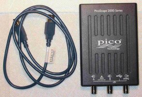
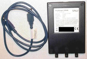
But having discovered today the the PICO Scope Model #2204A Kit with Probes and such could be had for under $150.00, I pulled the trigger and ordered one. After watching these Videos, observing the richness of the PICO Scope Software Features and its Additional Memory Storage capabilities is what finally sold me on this idea… and the Low Price could NOT be Beat either!

I opted to get the $130.00 PICO Scope Moedl #2204A Kit because I already have a Pair of 20:1 Attenuators, the separate Hantek Model# 650C High Amperage and Hantek Model #65C Low Amperage Clamps. I've also got the necessary Probes and Cabling required as well.

These items of course will eventually need to be obtained in order to perform the Main Tasks these Devices can do and for diagnosing all manner of other Automotive Problems… Largely... 'Grease Free'.

https://www.ebay.com/sch/i.html?_from=R40&_trksid=p2380057.m570.l1313&_nkw=Pico+2204A+PicoScope+2+channel+++AWG,+10MHz,+Includes+probes&_sacat=0
 
Last edited:
  • Like
Reactions: Tankcruiser

mrrsm

Original poster
Lifetime VIP Donor
Supporting Donor
Member
Oct 22, 2015
8,246
Tampa Bay Area
First Off... Visit THIS Link to view the PICO-Scope Model #2204A Kit “Un-Boxed”:

https://www.flickr.com/photos/126111508@N07/albums/72157719655570024

...and get your Latest, Greatest FREE version of the PICO-Scope OEM Software… HERE:

https://oem.picoauto.com/p7beta/download

Second… We often talk about WHY being a “Parts Changer” is the Ultimate Anti-Solution to most Automotive Engine & System Repairs and it always draws our focused attention and ire for THESE Reasons:

(1) It’s Time Consuming, often Wasteful & Laborious and can be VERY EXPENSIVE.
(2) It may turn out that NOTHING bought and installed actually solves the Problems.
(3) Deciding NOT to use OEM Parts in combination can invite “An Accumulation of Errors”.
(4) There are SOME types of Failures that will NEVER be discovered W/O using a Lab Scope.
(5) There is NOTHING to Learn from Tackling Repair Problems in this Poor Manner… other than experiencing FRUSTRATION & FUTILITY.

For our “Case In Point”, Please indulge the viewing of Eric “O” from the South Main Auto Channel investigating a Dual Crankshaft vs. Camshaft Correlation Problem on a Honda Vehicle throwing Codes that defy any obvious Mechanical Part Failure explanation. The MOST Important aspects here being:

(1) It would be IMPOSSIBLE to “SEE” what the Problems were here without using a PICO-Scope.*

(2) It would be IMPOSSIBLE to “Confirm” the Success of the Repair without using a PICO-Scope.*

I cannot stress this enough… ALL Lab Scopes ONLY show the Visual Representation of "Voltage over Time" and manipulate the information from ALL Automotive Sensors over a wide range of Voltages and Times Scales to make the Invisible behavior of our Engines...VISIBLE. To paraphrase Arthur C. Clarke... "THIS Diagnostic Gear is indistinguishable... from MAGIC!"

In a VERY satisfying way… Eric “O” shows us that by using KNOWN WAVE FORM PATTERN IMAGES for comparison, very slight and subtle Engine Misbehavior that cannot be seen with The Naked Eye… will become as Plain as The Nose on Your Face when viewed on a Lab Scope Screen during his thoughtful explanations:


*Substitute Hantek Model# 1008C (8) Channel Oscilloscope, if preferred. I will be using both from now on depending upon the need for additional Channels (6-8 EFIs, for example). But among OTHER Software Advantages offered by the PICO-Scope Model# 2204A is that it also comes with an AWG (Arbitrary Wave Form Generator) which can come in VERY Handy when Diagnosing everything from Speedometers and Tachometers to Oxygen Sensors. :>)

PS...

THIS Video Shows the Five Basic Things to Do with your PCIO-Scope EACH & EVERY Time You Use It:


Attachments

  • IMG_5346.jpeg
    IMG_5346.jpeg
    532.6 KB · Views: 1
  • IMG_5348.jpeg
    IMG_5348.jpeg
    487.5 KB · Views: 1
  • IMG_5353.jpeg
    IMG_5353.jpeg
    247.8 KB · Views: 1
  • IMG_5354.jpeg
    IMG_5354.jpeg
    573.5 KB · Views: 1
Last edited:

mrrsm

Original poster
Lifetime VIP Donor
Supporting Donor
Member
Oct 22, 2015
8,246
Tampa Bay Area
Whenever problems with the Throttle Body or ACC Pedal vs. Reduced Power Mode events have occurred, on more than one occasion we have been correctly steered by @Mooseman to “Un-Plug the Electro-Viscous Fan Connector…” to isolate the problem as involving the Shared 5 Volt Reference Signal WITH The PCM.

But… Thanks to THIS unusual investigation, we now have the chance to actually SEE a (4) Channel Oscilloscope In Action and observe precisely WHY this has happened. Follow along with this “Noisy Shop” In-The-Field Diagnosis of an otherwise intractable “Ghost in The Machine” problem with an intermittent P060E Reduced Power Mode Case Study happening to A Haunted 2006 Trailblazer.

Please note that we do have a prior incidence involving this exact P060E issue with a Saab 97x as documented (Unsolved) on this Thread:

https://gmtnation.com/forums/threads/saab-9-7x-p060e-rep-stabilitrak-off.5944/

During the Video, the VOP mentions that the All-Data solution winds up suggesting “Replace the PCM” from a Short List of Diagnostic Checks vs. Pass-Fail of Powers & Grounds, etc. But in this interesting Case Study, the Talented VOP (Video Original Poster) tears into this same weird Reduced Power Mode issue and shows us some remarkable things while using his High End Snap-On Scan-Tool AND his PICO Four Channel Oscilloscope for observing the Wave Forms of the APP Sensor, the Throttle Position Sensor. And finally, we can see that 'The Elephant in The Room' is the Electro-Viscous Fan Clutch’s misbehavior of its Fan Speed Sensor Feature gumming up the Common 5 Volt Reference Signal by some strange Feed Back phenomena ... in VIVID Detail:


For THIS Particular approach… using the Hantek Model #1008C (8) Channel Scope is the obvious better choice over the PICO Model 2204A since it only has the (2) Channel Ports.

The VOP ends this Case Study with the Comment, "You Won't Find anything like THAT on a Flow Chart..."
Using a Diagnostic Oscilloscope? Priceless ...and in THIS Case? FTW!

PS...

I keep trying to get @TJBaker57 to engage with using any of the variety of inexpensive Oscilloscopes on the Market... without much success so far... But since his main focus has been with PID Creation on an Android Device...perhaps by downloading and installing THIS APP... he could take full advantage of adding Oscilloscopes to his already impressive Torque App PID Design regimen and contributions. GOK (God Only Knows) how many more insights we would have on the GMT360 Platform for complex system diagnostics if he was also another advocate for using Oscilloscopes, too. Here goes nuthin'...


Last edited:

mrrsm

Original poster
Lifetime VIP Donor
Supporting Donor
Member
Oct 22, 2015
8,246
Tampa Bay Area
How do you get the PICO 4 Channel Scope Automotive Suite to Work on the PICO Model #2204A Scope:

Delete the OEM.DLL File from the PICO Software

Here's How:


TESTING Electronic Fuel Injectors using a PICO-Scope Model #2204A:

As a Real World Automotive Example, check out how useful these devices can be by adding to your abilities to Perform Definitive Oscilloscope Diagnostics:

Take the situation that @BrianF is presently involved with while working on the 5.3L Engine in his “Project Beater Silverado”. The Question he voiced recently was his concern about the Performance of the EFIs as possibly being involved in the rash of P0300 events his Scanner has detected. Lean Misfires can very easily be caused by Vacuum Leaks, a Failing Fuel Pump, Bad Coils On Plugs events ...or by having Errant EFIs.

If you assume that some or all of the EFIs might be the problem, you might think that the next steps would involve taking the Time, Labor & Expense necessary to pull the EFI harnesses, the Fuel Rails and the Eight EFIs off both banks of the Engine and either replace them as a Full Set or send them all out for an ASNU Pressure Cleaning, Right? Nope. NOT without checking on them non-invasively FIRST by using a PICO-Scope and while the Engine is RUNNING.

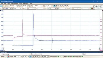
After Hooking Up the Laptop (or Windows Tablet) to the PICO-Scope with the correct Probe(s) and a 20:1 Attenuator in between it and Engine, you’d want to look at the attached image of the comparison between a BAD EFI Waveform like the one appearing in Pink-Red and then judge it against the Known GOOD EFI Waveform on the screen in the color Blue.

In diagnosing their differences, observe that the Blue Waveform Trace is level, even and has a Rectangular Current Ramp as the Injector is being momentarily Energized and Spraying. Then, as it De-Energizes, the EMF Collapses into the EFI and the Trace Spikes to high and Sharp Peak on the screen.

Then the Trace glides downwards in an Arc on a Steep Slope to the Right where you can also see a ‘very small bump’ in the Blue Image Trace Line. THAT is the precise point at which the Pintle (Pintel) Valve has Closed inside of a Properly Working EFI. Contrast the sketchy Pink Trace above it on screen that bears no indication of that “little bump”.

These Two Videos provide additional views and dialogue about using tis Equipment for EFI Waveform Analysis. Please Note that the Live, On-Screen connected EFI Voltage Waveform Trace is displayed in RED :

Part 1:

Testing an EFI for Voltage, Ground and Resistance Probing using the PICO-Scope Model# 2204A:


Part 2:

Testing the Current Ramp Flow on the EFI Circuit using a PICO-Scope along with the inexpensive Hantek CC-65 Low Amperage Current Clamp:


Attachments

  • PICOSCOPEEFICOMPARISON.jpg
    PICOSCOPEEFICOMPARISON.jpg
    466.8 KB · Views: 5
Last edited:

mrrsm

Original poster
Lifetime VIP Donor
Supporting Donor
Member
Oct 22, 2015
8,246
Tampa Bay Area
And again...on behalf of @BrianF... Here is a Video of How to Use the Oscilloscope to Check the Coil On Plugs as the Cause of Misfires. Using the following Items, the best part of this effort is that without having to R&R anything from the Motor, you can perform this In-Depth COPs Diagnosis in just a matter of minutes:

(1) A Windows Laptop Computer or Tablet
(2) A PICO-Scope Model# 2204A Oscilloscope
(3) A Hantek 20:1 Voltage Attenuator
(4) Channel A & B Probes
(5) And Last but not Least... A Coin... (A Quarter will do Nicely) ***


*** The POSITION and SIZE of the Coin might either improve or degrade the Reading on screen as per THIS Follow Up Video:

 
  • Like
Reactions: BrianF

mrrsm

Original poster
Lifetime VIP Donor
Supporting Donor
Member
Oct 22, 2015
8,246
Tampa Bay Area
NP @BrianF ... I should have mentioned that after you have visited and Downloaded the latest PICO Software... You can Practice just as though you already have the Scope... without actually needing one to "get your feet wet" with these unfamiliar concepts. Once you dial in on how GOOD it is do work with these Tools...there is NO GOING BACK.

Credit ALL of this information to "mechanics mindset" Youtuber


Here are some Amazon Resource Links to have access to all of the Gear being covered in this Oscilloscope Thread:

Here is the Link to FREE PICOScope Waveforms:


USA Product Links:

PicoScope 2000 Series - https://amzn.to/39shJtc
Hantek Automotive Leads x2 - https://amzn.to/300TCyL
Hantek 20:1 Attenuator - https://amzn.to/3eWAzKc
Back Probes - https://amzn.to/3iKBsuA
Alligator Clips - https://amzn.to/3jGeMtR
Ancel FX9000 - https://amzn.to/37KIskQ

UK Product Links:


PicoScope 2000 Series - https://amzn.to/314P89D
Automotive Leads x2 - https://amzn.to/3fj7Yiv
20:1 Attenuator - https://amzn.to/2EAnbyR
Back Probes - https://amzn.to/3m3VGkY
Alligator Clips - https://amzn.to/318INtF
Thinktool Mini OBD - https://amzn.to/3z0TDla

PS... For Linux Mint and Ubuntu Users:

Last Night I Hacked the Latest PICO-Scope Beta 7 Automotive APP in the Linux Kernel and figured out How to Get the PICO-Scope Model# 2204A Hardware to work with this Great APP meant for use with the Higher End PICO Hardware. For "Step By Step" instructions on what to do to make this work... Please visit THIS Thread:


mrrsm

Original poster
Lifetime VIP Donor
Supporting Donor
Member
Oct 22, 2015
8,246
Tampa Bay Area
This nearly One Hour Long Video is a "One Over The World" comparison "Shoot Out" between the dominant Automotive Oscilloscopes on the Market using a 2014 GMC Sierra as the Truck Test Bed and covering a Wide Range of Sensors and Modules.

Strangely, the Hantek Model # 1008C was omitted from the list of 'Combatants', but the PICO-Scope Model# 2204A managed to hold up its head quite high very well during the majority of these Tests.

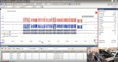
Again, I hate to keep taking @TJBaker57 's name in Vein... (uh...err... Vain) But in this instance, Thomas might want to see first hand how the PICO #2204A (2) Channel Oscilloscope is actually capable of Graphically Decoding CAN-Bus High and Low Signal Data on the fly. THIS is a Graph with Text feature ordinarily left to the likes of the Higher End Professional Automotive Scopes.

If there is ANYBODY here at GMTN that understands what the implications are for quickly analyzing Network Data Packets, he will know for sure that THIS entire Video is worth studying. However, concerning JUST the CAN-Bus Network Diagnostic particulars mentioned above, check it out from around 2:55 and onward into the viewing:


Attachments

  • PICODECODESCANBUSDATA.jpg
    PICODECODESCANBUSDATA.jpg
    985 KB · Views: 2
Last edited:

mrrsm

Original poster
Lifetime VIP Donor
Supporting Donor
Member
Oct 22, 2015
8,246
Tampa Bay Area
Soon, I'll be expanding on some of the additional Support Peripherals such as "How to Use an In-Cylinder Pressure Transducer on GM 4.2L and 5.3L LS Engines" that will include some excellent Screen Shots of what their "Rare, Known Good GM Transducer Wave Forms" are SUPPOSED to look like...and How to Interpret their On-Screen appearances, including what the DOD Active Cylinder performances should look like, too.

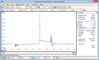
In the mean time... I thought it would be practical to make mention of the fact that the OEM PICO-Scope Tranducer Kits (WS-500) can cost close to $1,000.00 and the likewise useful "PICO Paddle(s)" employed for Diagnosing Failing Coil On Plugs (COPs) and perhaps even Failing Electronic Fuel Injectors (EFIs) are also VERY expensive as well at around $500.00:

PicoScope-COP-Setup.pngpicocop1probe.png

But... Take Heart, Gentlemen (and Ladies)...as I've recently purchased the right type of inexpensive 0-275 PSI Pressure Transducers via eBay Searches that WILL operate in a Range of 0.5 to 4.5 Volts DC and also be capable of showing Negative Pressure Voltage readings via a fairly reasonable Sample rate whenever the Oscilloscope(s) are measuring the Partial Vacuum that SHOULD happen during the 720 Degrees normal 4-Cycle Events... just at the point where the Piston is on its downward travel when ALL of the Intake and Exhaust Valves are briefly closed, post Compression & Ignition Strokes.

Although I paid in the range of $50.00 to $75.00 for the ones I've ordered for some Made In USA versions, in general, these will cost you around $15.00 to $20.00 (From China).

While certainly not being as sensitive with their Sampling Rates as the Very Expensive PICO Brand Name version produce, these will still work well enough to perform "Running In-Cylinder Compression Tests" that can then be analyzed using the PICO Automotive Suite after setting up a properly calibrated "Custom Probe" then visualized on either the PICO or Hantek Oscilloscope screens using their own Software.

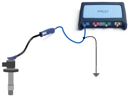
So my specific purpose today in mentioning these ordinarily overly pricey tools, without actually covering their set up and use on vehicles is to alert everyone about finding an inexpensive alternative "Paddle" Grounded BNC Sensor for Diagnosing COPs and EFIs on any Oscilloscope, courtesy :

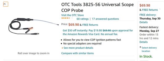
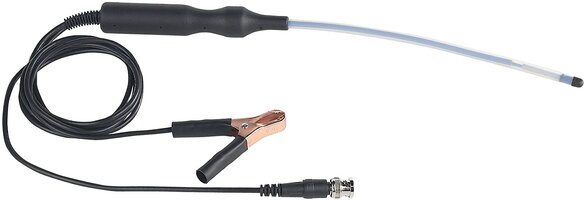
OTC Tools Model# 3825-56 Universal Scope COP Probe:

https://www.amazon.com/dp/B009TCCIFA/?tag=gmtnation-20

$70.00 Beats $1,000.00 for an Entry Level Digital Oscilloscope Tool... Hands Down!

OTC3825-56COP1PROBE2.jpgOTC3825-56COP1PROBE.jpg

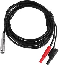
I should also mention that getting a pair (or more) of these Hantek Automotive BNC-to-Banana Style Connectors will improve your Scope performance around excessive "In Bay" High Frequency Electronic interference and give you solid and reliable length and performance; regardless of which flavor Oscilloscopes you are using... or soon will be... :>)

Hantek Model # HT30A Heavy Duty Automotive BNC-to-Banana Cable Connector:

Amazon had THE Best Price Around on these at $16.00 per Cable!

https://www.amazon.com/dp/B01F7DN42A/?tag=gmtnation-20

HANTEKBNC2BANANACABLE0.jpgHANTEKBNC2BANANACABLE.jpg
 
Last edited:
  • Like
Reactions: Expeditor

mrrsm

Original poster
Lifetime VIP Donor
Supporting Donor
Member
Oct 22, 2015
8,246
Tampa Bay Area
In this cool Video… “The Man from PHAD…” Crazy Ivan from Pine Hollow Auto Diagnostics shows up in Avoca, New York and pairs up with Eric “O” from SMA on site at South Main Auto to work out some COP (Coil On Plug) issues and demonstrate How to Use an Oscilloscope AND a DMM in tandem for Diagnosing COP causation with Intermittent “Fish Bite” Misfires on a Chrysler Truck 4.7L Engine and get the chance to capture Known Good AND Known Bad COP Wave Forms for their future reference:

Keep an Open Mind and Don’t be too inclined... to ‘Shine THIS One on’ just because ‘They’re NOT Talking about a Chevrolet…”. The reasoning here is simple: ALL Electronic and Electrical Automotive components universally follow the Rules of The Road where Electromagnetism is concerned. So it should never matter about the Brand/Make/Model of the Vehicles.

Just follow the principles being demonstrated in these kinds of Diagnostics and you’ll be able to expand your knowledge and become much more confident when using your OWN Oscilloscopes. Besides that… They actually FINISH this Story ...with an honorable mention of a TBSS TRAILBLAZER :>)

The central theme in this Video is to be able to simultaneously visualize both the Primary Coil Current Ramp (Using a Low AMP Clamp on Channel One) AND be able to observe the Secondary Voltage Wave Form firing the Spark Plugs on Channel Two in order to determine which side of the circuit is causing the problem. Eric “O” and Crazy Ivan spend enough time at “The White Board” to break down what the Wave Forms represent and then clear up any misgivings or questions you might have about the “How?” and “Why?” COPs and/or the entire Ignition Circuits can FAIL:


THIS was a genuinely sinful pleasure to be able to watch two of a few of my favorite Professional Automotive Diagnosticians ‘at play’… so take note of Ivan’s Extended Channels at his Links below to a few other Auto Pros that are also worth checking out for more Tips and Techniques when using Automotive Oscilloscopes on your Vehicles:

https://www.youtube.com/channel/UCn4Ifss-t3wMT6VBzQoKPUA

https://www.youtube.com/c/PineHollowAutoDiagnostics/about

PS...

In the Video below, an AliExpress Vendor describes how to set up my Hantek Hand-Held Model# 2D82A (Auto) Oscilloscope that is just CHOCK FULL of 80 Pre-Set Automotive Diagnostic Choices, showing the array of Cables that come in very handy for all manner of Under The Hood Oscilloscope Analysis. Bear in mind the VOP's difficult narrative involves the Language Barrier between his Chinese to English challenge:


The Two Gurus above made use of an 'Old Subaru Coil On Plug Harness' unit that is actually available from Hantek as a Specialty COP High Tension Pick Up Lead Extension System (for under $15.00) that will work with ANY Oscilloscope as Demo'd in the second Video in this Post:


61FeIhkje-L._SL1500_.jpg61zecUeb2uL._SL1500_.jpg61jTbZBt1YL._SL1500_.jpg51izNM3tPZL._SL1500_.jpg61h1MHKbcaL._SL1500_.jpg610-+eO5RhL._SL1500_.jpg
 
Last edited:
  • Love
Reactions: azswiss

mrrsm

Original poster
Lifetime VIP Donor
Supporting Donor
Member
Oct 22, 2015
8,246
Tampa Bay Area
Interpreting the subtleties in Wave Forms will be a Mystery for most of us ...at FIRST. But with some exposure to using your PICO or HANTEK Oscilloscopes and with some practice in using them on Decent Running Machines... or by picking adjacent, GOOD performing Cylinders for comparison and recording their various component Wave Forms on Poorly Performing Motors, you'll soon get to know your Engine in a way NOT otherwise possible; NOT even if you physically tear the Motor apart... Right down to its ATOMS.

In this Example Video... Paul "Scanner" Danner is examining a P0300 Code on a GM V6 Engine that he will discover is suffering from having a Stuck Fuel Injector that is Mechanically FROZEN CLOSED.

(1) First, he uses his High End Scanner to view the overall Live and Historic Cylinder Misfire Counts to narrow down the "Problem Child".

(2) Then he uses his Verus Oscilloscope Feature to display the Secondary Ignition Wave Forms of All (6) Coils... looking for any Bad Ones. But the character of this Secondary Ignition Wave Form clues him in about the Lean Cylinder Conditions present only in the #5 Cylinder during a "Snap Throttle" portion of the Test.

(3) Paul then Back Probes the #5 Cylinder EFI to show us what a BAD Live Fuel Injector Wave Form looks like when compared to a Saved Known Good EFI Wave Form. After observing this action, you can apply this experience to recognize this problem happening to ANY Fuel Injector in any other type of Vehicle or 4 Cycle Gasoline Engine.

(4) Once "Scannerdanner" shows you what to look for... Spotting the Actual Problem will become second nature to you and will NOT involve swapping parts without need and provide definitive proof of what has REALLY Gone Wrong:


mrrsm

Original poster
Lifetime VIP Donor
Supporting Donor
Member
Oct 22, 2015
8,246
Tampa Bay Area
Check out just how quickly "Keith from New Level Auto" manages to Diagnose a Failed Instrument Panel Cluster (IPC) on a 2002 Chevrolet Trailblazer using an AESwave U-Probe Oscilloscope with a Single Pin Back Probe plugged into a Hantek 'BNC to Banana Connector' Cable.

In this instance, he not only tests the Powers and Grounds on screen with each related IPC Connector Wire, but he also proves out the Class 2 Network Functionality as well. THIS action cannot be done merely with a Standard DMM:


If you want to try something else out other than the PICO or a Hantek O-Scopes... check out the features of this $160.00 After-Market Tablet-Style Oscilloscope via Amazon:


NOTE:

Keep this guy "Keith from New Level Auto" in mind whenever investigating ANY Electrical or Electronic Network Diagnostic issues as HE is 'THE Man' who Trained 'THE Will Robinson' from "Robinson's Auto" with using a Tech 2, a PICO Oscilloscope and a 16 Pin Break Out Box to successfully trace down UXXXX Code issues on a GMT360 in another YT Video. HE ...is a One Very Smart Dude.
 
  • Love
Reactions: azswiss

mrrsm

Original poster
Lifetime VIP Donor
Supporting Donor
Member
Oct 22, 2015
8,246
Tampa Bay Area
In a bit of ‘cool serendipity’… I get to demonstrate the value of using both an Oscilloscope AND an Infra-Red Camera while trying to Diagnose what LOOKS at first glance like a “Failed Ignition Coil” but turns out to be a FUBAR’d MOSFET Circuit inside of a BMW 6 Cylinder PCM.

Remember Guys… We're talking about the Universal Nature of ELECTRICITY here, so “Diagnosedan” ‘s Video Training Example being observed ...is PRICELESS!

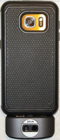
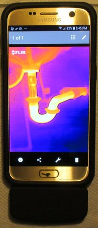
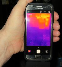
At the same time, I can make mention of my recent purchase of a very affordable FLIR ONE Infra-Red Camera device for use on my Samsung Galaxy S7 (see the images below) that for just a few hundred bucks… does EXACTLY what the $1,500 Snap-On FLIR Camera central to Dan’s Diagnosis will show during this Video:

FLIRONE5.jpgFLIRONE7.jpgFLIRONE8.jpg

This is Important:

It NEVER Gets Beyond The BASIC FUNDAMENTALS…

The Oscilloscope and the FLIR Camera being demonstrated here as Good Diagnostics Tools (Used Before AND AFTER as PROOF of a Successful Repair) are simply ADDITIONAL items to add to your present regimen of Good Hand Tools, Good Common Sense and Good Training and Experience with how to use them:

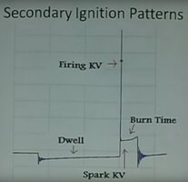
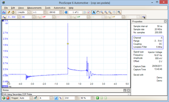
Before we ‘Start The Movie’… Check Out this Autopsy Image of what a Proper, Good, Known Secondary Ignition Coil Wave Form looks like, so you can spot the proper nomenclature and the know the differences that will show up between the Known Good Wave Forms on Dan’s Oscilloscope… and the possible Bad (or Missing) Ones he observes on his Scope:

IGNITIONPATTERNANALYSIS.jpg

 
Last edited:
  • Like
Reactions: azswiss

mrrsm

Original poster
Lifetime VIP Donor
Supporting Donor
Member
Oct 22, 2015
8,246
Tampa Bay Area
2006 Colorado Engine Sets a P0017 Code: An SMA Case Study:

"You Can't Tell The Players... WITHOUT a Program!"

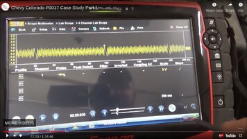
In this case, we are getting a very lengthy look into Diagnosing and Fixing a 2006 Colorado 4 Cylinder Motor throwing a P0017 Code as Eric "O" from SMA (South Main Auto) starts off by "Pulling His Hair Out" because he did NOT possess any 'Good Known Wave Forms' of the Engine Sensors.

The SMA Genius takes us along for the ride while performing this Five Part Video Series conducting these P0017 Diagnostics & Repair using his High End Snap-On Verus Scanner & Oscilloscope to be able to investigate this "Camshaft-Crankshaft Correlation" Study.

ALL of the actions he takes can be replicated with either a (2) Channel PICO-Scope Model # 2204A or an (8) Channel Hantek Model# 1008C Scope.

Possible Causes for P0017:

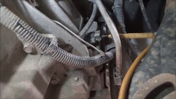
(1) Physical Damage related to the Crankshaft Mains Thrust Bearing disintegrating or falling out and causing a cascade of Codes related to the Crankshaft (Two Wire A/C Magnetic Pulse Sine Wave) vs. the Camshaft (Three Wire Hall Effect Square Wave) Correlation getting Way Out Of Sync.

(2) Timing Chain Set Damage from Excessive Timing Chain Guide Wear and Timing Chain Stretching Excessively on a High Mileage Engine.

At around 19 Minutes along into the First Video... Eric "O" makes this telling comment:

"I suppose we ought to Hook a Scope to this Thing ...and see what Things LOOK Like..."

It will help to enjoy a few Pots of Coffee while watching these (5) Videos and be prepared to make some notes on HOW Eric "O" Hooks up his Two Channel Oscilloscope Probes to the CPS, CPAS and CKP Sensors. Observe HOW he sets up the 'Trigger Point' for the CKP Probe to align all of the Probe Output Signals on screen for 720 Degrees of Crank and Cam Motions.

@Mooseman will appreciate How Much MORE WORK is involved with Eric "O" performing the Timing Chain Set R&R of a GM Vortec Atlas 4 Cylinder Variant ON CAMERA as being a TOTAL NIGHTMARE even with having Two Less Cylinders AND doing this work in a Colorado Pick Up Truck WITH a Pro Shop Lift. And All THIS ... just to get a Decent CPS vs. CKP Wave Form !!!

... So Let the FUN Begin
:


Part 1:

Part 2:

Part 3:

Part 4:

Part 5:
 
Last edited:
  • Love
Reactions: 808

mrrsm

Original poster
Lifetime VIP Donor
Supporting Donor
Member
Oct 22, 2015
8,246
Tampa Bay Area
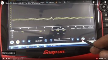
Just to round off the corners on the Proper Oscilloscope Equipment Set Up to use ... EACH and EVERY Time... regardless of Brand-Make-Model… at 26:55 into Video Number 1 of 5 for the P0017 Diagnosis in Post #21 above, Eric “O” demonstrates a problem where he was hooking up his Channel A (1) Back Probe Needle to the CKP Sensor...

CKPSCOPESIGNALPROBE.jpg

but he chose to GROUND the O-Scope Black Wire Alligator Clip locally to a Bolt on the Transmission… and he lost the On-Screen Signal Trace:

CKPSCOPESIGNALPROBEGROUND.jpg

So the Good Rule of Thumb in ALL instances should be to Run Line to the BATTERY NEGATIVE POST ---every time--- and avoid getting any erratic issues with inexplicable Signal Drop Outs on the Oscilloscope Screen from using ANY localized “P*SS -POOR” Grounds. Otherwise, this can become a regularly confusing O-Scope issue.

In numerous Videos from “New Level Auto” when performing the odd & and sundry O-Scope Diagnostics, Keith has stressed, “I don’t care if I have to run a separate 50 Foot Grounding Wire all the way back to the Negative Battery Post… THAT is what I will do each and every time to ensure that I have a GOOD GROUND…” :>)

For example… Consider his use of a Separate Ground Cable when Back-Probing the Lift Gate Module Sensor Signal Wire leading to and from the (-) Negative Battery Terminal for his PICO-Scope.

...another "Thing"...

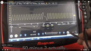
Check out the appearance of what a "Proper Wave Form" of any Two Wire A/C Sine Wave created by the Permanent Magnet inside of the CKP Sensor. THIS is what it should look like with its slightly Taller and Stretched Out S Wave demarcation point:

P0017CASESTUDY32.jpgP0017CASESTUDY2.jpgP0017CASESTUDY1.jpg

Choose that image portion as the starting location for your On-Screen Trigger Point and then you can perform the necessary “Tooth Count” in between these Trigger Events; in this case 58 (Err…I meant 60 Minus 2 Actually) to confirm the working reliability of the CKP’s Magnetic Inductance A/C Electrical Wave Form Pattern on a properly functioning sensor.

If symmetrical and showing a correct "Tooth Count", this On-Screen Pattern will also confirm that the Spot Welds holding the Reluctor Ring onto the Crankshaft adjacent to the CKP Sensor Mount Port (hole) in the Engine Block are sound and have not broken loose.
 
Last edited:
  • Love
Reactions: 808

mrrsm

Original poster
Lifetime VIP Donor
Supporting Donor
Member
Oct 22, 2015
8,246
Tampa Bay Area
Well... I don't know how I managed to put everybody through all of THAT without actually showing the Differences between the Good vs. the Bad Wave Forms and explaining what to look for:

(1) With the Crankshaft being represented as a 360 Degree Circle... each individual Tooth on the Crankshaft Reluctor represents 6 Degrees... therefore it requires 60 Teeth (Minus Two to demarcate for Timing Events) cut into the OD of the Crankshaft Reluctor Ring to create a completed Circle.

(2) All Oscilloscopes will display the Output of the CKP Permanent Magnetic Pick Up from the Peak of Each Individual Tooth as a Sine Wave created by the Alternating Current, rising and falling during Crankshaft rotation and Tooth Proximity to the Permanent Magnet and Induction Coil.

(3) The CPS Camshaft Position Sensor (Absolute) creates a Hall Effect Square Wave from either 4,5 or 6 Notches built into the Camshaft Phaser OD creating either 4, 5 or 6 Square Waves passing in its orbit on the Exhaust Camshaft either as a wide or thin Rectangular Shape as the Sensor picks up the gaps in between each of these notches depending upon the Number of Cylinders present in the Atlas Vortec Motor.

(4) By creating Live and Still Frame captures of the differing actions between the Crankshaft and Camshaft, the visual imagery of this correlation (positions) between the Sine Waves of the CKP Sensor and the Square Waves of the CPS Sensor, the Oscilloscope lends itself to making an easy comparison.

(5) The Question of whether or not this Correlation is OUT OF SYNC is determined by measuring what is happening within the same Time Scale... or in the case of having a Know Good Wave Form, by simply Counting the CKP Sine Wave Points and figuring out if there are either MORE or Less than should be present between the two.

(6) In the case of having MORE CKP Sine Wave Peaks ...it becomes readily evident that the Timing Chain Hardware has become either Worn In or Stretched Out and LOOSE.

(7) These disparate conditions will make it impossible for the PCM to accurately Time EFI Injections and Spark Plug Firing Events BTDC and will result in throwing the P0017 Code.

In the case of this Known Good CKP Wave Form, it was recorded within just a few minutes after a Complete OEM Timing Chain Set Replacement was performed on the Four Cylinder Variant of the Atlas Engines in a Colorado Truck.

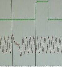
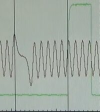
Note that the measurements are being made "From Peak To Peak" between the Point of the Missing Two Teeth and the location where the Falling Sine Wave of the CKP (BLACK LINE) meets the Rising edge of the Square Wave of the CPS (GREEN LINE). The Number of individual upper points of the Sine Wave in between should be counted (in this case... Four)

GOODCRANKWAVEFORM.jpg

But... in the case of this Very Same Engine being Diagnosed on a prior occasion with the same Scope after throwing a P0017 Code... THIS is what appeared on Screen as a Bad Wave Form for a CKP Sensor:

BADCRANKWAVEFORM.jpg

Notice that there are Five (+) Sine Wave Points within the same Horizontal Time Scale, offering definitive proof that the Timing Chain Set is either stretched or worn out and incapable of achieving a proper Camshaft to Crankshaft Correlation. The only solution here was the replacement of the Timing Chain Set and its associated Hardware.
 
  • Like
  • Love
Reactions: 808 and azswiss

mrrsm

Original poster
Lifetime VIP Donor
Supporting Donor
Member
Oct 22, 2015
8,246
Tampa Bay Area
This Video and attached images describe how to Diagnose a FUBAR'd Class 2 Network caused by an Errant EABS Module on an Avalanche Truck, making clear Network Communications between the PCM, the BCM and other Onboard Modules impossible.

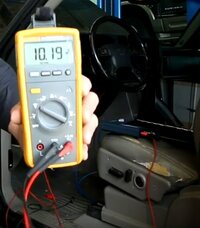
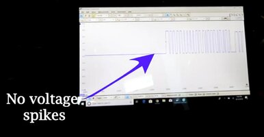
The VOP located the Splice Pack (Serial Comms Comb Pack) under the Dashboard at the Driver’s Knee Bolster ...but before he un-plugged it, he checked the DLC Terminall for Powers & Grounds using a DMM and found the Network Voltage was being PULLED HIGH to 10.19 Volts DC vs. the expected, normally rapidly fluctuating 0-7 Volts DC:

DMMSPLICEPACKDIAGS1.jpg

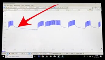
Take Note of the Visual Differences between the Network being pulled HIGH showing on the Screen as this BAD Wave Form:

BAD Wave Form (Voltage Shorted HIGH to 10.19 Volts)


PICOSCOPECLASS2NETGOESHIGH.jpg

... versus how the Network PWM Signals behave via the Known Good Wave Form that appears on the Laptop Computer Screen while using a PICO-Scope Unit along with the FREE PICO Diagnostic Software after the EABS Unit got disconnected:

Known Good Wave Form (Voltage Normal @ 0-7 Volts DC):

PICOSCOPECLASS2NETGOESNORMAL.jpg


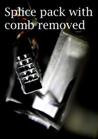
The VOP pulled the Splice Pack Comb and then systematically checked all of the Modules connected to the Single Wire Class 2 Network Bus by bringing them back on line ...one at a time:

LATEMODELSPLICEPACK1.jpgLATEMODELSPLICEPACK2.jpg

After identifying the errant EBMS Unit, the VOP disconnected the Unit and the PWM Comms on the Class 2 Network returned to Normal (0-7 Volts DC). He used the PICO-Scope Unit connected between the Vehicle and his Laptop Computer to visualize the PWM and Voltage-Over-Time Behavior to Diagnose the problem visually.

But most important to this happy outcome was being able to confirm the actual Problem AND that the Repairs he attempted actually WORKED ...without having to resort to using a 'Parts Cannon'.


This Post above is quite complementary to the related Video coming generously from Will Robinson's Auto for more In-Depth coverage of how to investigate this identical problem using a Tech 2, PICO Scope and a Windows Tablet... but caused by a DIFFERENT Errant Module:


PICO-Scope…. FTW
 
Last edited:
  • Like
Reactions: azswiss

mrrsm

Original poster
Lifetime VIP Donor
Supporting Donor
Member
Oct 22, 2015
8,246
Tampa Bay Area
In his Classroom White Board Setting, Paul "Scanner" Danner shows "How to Use a PICO-Scope to Test a MAF Sensor"


...the Follow Up Video with the MAF hitting "Out Of Range" P-Codes:

 
Last edited:

mrrsm

Original poster
Lifetime VIP Donor
Supporting Donor
Member
Oct 22, 2015
8,246
Tampa Bay Area
Back in 2013, Paul “Scanner” Danner showed off his then New AES Wave “U-Scope” Oscilloscope with an Induction Coil Clamp Sensor Cable while demonstrating how EASY it is to perform Ignition Coil Wave Form Diagnostics:

Use the "Known Good Wave Form" of a properly working Ignition Coil being sensed using a Paddle Probe instead of an Induction Coil Clamp for a comparison to what you see in the Video:

158256-8910d1d8b99688ef09319a7e41988665.png


Here is a more In Depth look at the AES Wave “U-Scope” Oscilloscope Set Up and Settings Options:


...and even more Information:

 
Last edited:

mrrsm

Original poster
Lifetime VIP Donor
Supporting Donor
Member
Oct 22, 2015
8,246
Tampa Bay Area
Okay… By now most of you will have figured out that above ALL things, I think it will be important NOT TO BE AFRAID OF AN OSCILLOSCOPE… if you are ever going to get anywhere with using one as a Tool of Discovery and Problem Solving.

There is enough good, instructive information out and about now on the Internet “O” Scope Tech Blogs and via YouTube Instructional Videos to be able to Shop for the RIGHT Information on WHICH Wave Forms to focus on and WHAT a Known Good Wave Form should look like when compared against whatever your “O”Scope On Screen Signals shows up looking like while Diagnosing your particular "Voltage over Time" problem(s) whether DC or A/C.

But even knowing THAT situation, it STILL might not be enough of an inducement to prevent the Knee-Jerk response some of us may have towards a seemingly indecipherable “Misfire” and simply “Replace ALL the Coil On Plugs AND the Plugs” or “Replace ALL The EFIs” just because using an Oscilloscope seems… “It’s Just Not Old School!” or… “It’s Just a Bit TOO Far OUT There for ME!”

But… Besides that… “Don’t Oscilloscopes Cost an Arm-N-A-Leg?”

Nope.


But… Besides that… “Don’t you HAVE to use a Laptop or a Tablet with one, TOO?”

Nope.


Not unless you WANT to use either the inexpensive PICO-Scope Model #2204 or the Hantek Model #1008C Versions…. Oh… And BOTH come with FREE Software that you can Download RIGHT NOW to use and practice with whenever you like

But… Besides that… “Don’t you need a LOT MORE Equipment, TOO? To Make it ALL Work?”

Naw
… Not TOO Much: (2) Grounded Probes, (2) HI & LO Amp Probes, (2) 20:1 Voltage Attenuators.

Besides that… “But Don’t I have to LEARN HOW TO DO SOMETHING NEW… TOO?”

Yup


But… You can pick and choose whatever you want to learn about and focus on for just what you need to do to fix many issues.

Besides that… “But I can’t use this Oscilloscope Equipment for ANYTHING ELSE… Right?”

Nope!


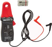
For example, If you get THIS ES-695 Tool to act as your Low Amperage Probe… It is capable of detecting VERY Low Levels of Amperage @ 100 mV/Amp and sensitive down to 0.01Amp/mV. This means that you can ALSO use this Tool for a Detecting Parasitic Draw when paired with a sensitive enough DVOM or a DMM. The switchable working Amp levels run from 2 Amps to 80 Amps

Simply plug in the Red & Black leads to your Meter and place the Tool Clamping Jaws around the Battery Ground Cable using its ½” Wide Clamp Opening. No need for any other Exotic Interfaces that might cause you to accidentally disconnect the Battery while searching for the problem and cause you to lose your PCM Settings. :>)

https://www.amazon.com/dp/B000FN4IUK/?tag=gmtnation-20

81n2R8sUi0L._AC_SL1500_.jpg

Compare the Price of (6) Brand New GM OEM ACDelco Coil On Plugs versus the cost of ALL the various Basic Equipment Elements needed for endless types of Oscilloscope Diagnostics… and then Draw Your Own Conclusions...
 

mrrsm

Original poster
Lifetime VIP Donor
Supporting Donor
Member
Oct 22, 2015
8,246
Tampa Bay Area
During a recent investigation of a Mysterious Problem of a Trailblazer suffering repeated incidents of having Fuse # 28 Burn Outs... the problem turned out to be from an Internally Shorted Coil Over Plug.

Replacing that Coil solved the OP's problem... but more information is needed to explain WHY this can occur. Here is what is helpful to know:

If your SUV suffers another Shorted Coil Over Plug Issue… Consider investigating these particular problems that will INVITE this failure to occur in the first place:

Excerpt from:


Combine a worn out spark plug with lean air/fuel mixture, and that 80kV is going to find an easier path to ground. Even the best insulator boot can’t contain it indefinitely; at first the spark will leak through the boot to the valve cover only during acceleration, but eventually it will happen all the time.

That’s why boots and connector springs are available separately on some models, so they can be replaced when installing new spark plugs. If the old spark plug has a carbon track on the ceramic, that boot should be replaced because there’s a matching track in the boot that offers an easy path to ground.

If there’s liquid in the spark plug well, even a new insulator boot might not be able to contain the secondary voltage. Chrysler issued a recall for the 2004-06 Dodge Durango (18-024-06) to replace ignition coils that were shorting through the (non replaceable) boot to the valve cover. The repair included installing a redesigned windshield cowl to keep rain water out of the engine compartment.

Other vehicles have had similar problems, but not just because of weather. Leaky spark plug tube seals, coolant leaks and even water or mud splashed up from below have all been known to cause this problem.”


Using an Oscilloscope and a Paddle Probe on the tops of the COPs while viewing the individual COPs On Screen Wave Forms will allow you to observe the Voltage Spike Height of the Secondary Coil response as it approaches the Danger Zone of 80 Kilo-volts and above which is an invitation for the Coil to seek an easier Path to the Internal Ground. No other Diagnostic Tool is capable of doing this!
 
Last edited:
mrrsm

Original poster
Lifetime VIP Donor
Supporting Donor
Member
Oct 22, 2015
8,246
Tampa Bay Area
In this First Demonstration… the VOP (Video Original Poster) Tech Demonstrates Two CRITICAL Concepts when using either the PICO-Scope Model# 2204A (...or later Variants) OR the Hantek Model #1008C Oscilloscopes whenever Back-Probing the High Voltage Outputs of ANY Cop Over Plug (COP) or ANY Single Coil Distributor Based Ignition System:

(1) It is NOT necessary to install a Hantek 20:1 Voltage Attenuator ahead of the BNC Probe Devices when using a Low Amp Clamp (2-80 AMPS) to indirectly read the Amperage on the Oscilloscopes by means of Electro-Magnetic Induction.

However…

(2) It is VERY NECESSARY to install a 20:1 Voltage Attenuator ahead of attaching ANY BNC Probes in order to avoid damaging this delicate equipment by exposing the PICO-Scope Model #2204 or the Hantek Model #1008C Oscilloscopes DIRECTLY to the High Voltage Output Side of the Secondary Coils of either the COP Style or the Single Coil Style with Distributor types of Ignition Systems.

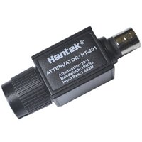
THIS is what a $10.00 Hantek 20:1 Voltage Attenuator looks like:

HANTEK20TO1ATTENUATOR.jpg

THIS is where to Get Them as a Handy PAIR to include in your “O” Scope Kit:

https://www.amazon.com/s?k=hantek+attenuator+ht-201&crid=2XYOMMNHEQ6S5&sprefix=HANTEK+ATTENU,aps,123&ref=nb_sb_ss_ts-doa-p_3_13


Here is a similar Demonstration being performed using a PICO-Scope Oscilloscope and a PICO-Scope COP Probe. Note that the PICO Technician has to Manually adjust practically everything in the PICO Automotive Laptop Software even before being able to use the PICO-COP Wand or Paddle:


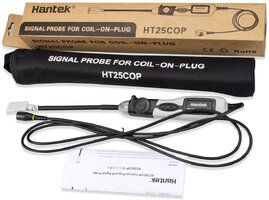
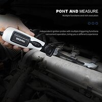
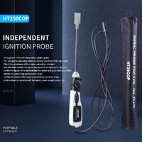
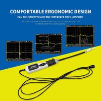
Here is a similar Demonstration of the Hantek Model# HT25COP being used to view the Secondary Wave Forms of a Transversely Mounted Engine using Coil Over Plug style Ignition Coils and being able to immediately view the Forms on a High End Hantek Hand-Held Oscilloscope that comes pre-programmed with over 80 Automotive Diagnostic Functions:

Take Note that the hand-Held Unit automatically performs ALL of the initial parameter Set Ups that properly position the Image Trigger in the middle of the Screen and instantly display the Wave Form in a manner that allows for Rapid and Uncomplicated Viewing ...without having to wade through various “choices” even before being able to USE these two Hantek Devices:


Hantek Model# HT25COP Signal Probe for Coil On Plug Coils… FTW...!

61PZc8glW9S._AC_SL1200_.jpg51QABKkanCS._AC_SL1200_.jpg41swxcKp2XS._AC_.jpg71Zh8gcCuxS._AC_SL1200_.jpg71c5Kf6oxCS._AC_SL1200_.jpg
 
Last edited:
  • Like
Reactions: azswiss

mrrsm

Original poster
Lifetime VIP Donor
Supporting Donor
Member
Oct 22, 2015
8,246
Tampa Bay Area
I realize that I brought the PICO-Scope Oscilloscope Model #2204A (2) Channel Unit into this Thread a bit after the Hantek Model # 1008C (8) Channel Scope, so I missed the opportunity of getting on the Ground Floor conceptually in Post #1 courtesy the Two Part “PICO-Scope Basics” YouTube Lessons for his Pro-Grade Classes provided below by Paul "Scanner" Danner back in 2013.

Nonetheless… since there will always be some variations amongst ALL Scopes with their unique Software Suite… getting familiar with the PICO-Scope Automotive Suite Most Basic Concepts in this manner will be important, regardless of which Model of Scope you eventually choose to purchase. I make a habit of Downloading and Reviewing Paul’s Training Videos like these ...every chance I get:

Part 1:


Part 2:


mrrsm

Original poster
Lifetime VIP Donor
Supporting Donor
Member
Oct 22, 2015
8,246
Tampa Bay Area
The Old Sage goes something like this….

If YOU Take Care of YOUR Equipment… IT Will Take Care of YOU…”

The Object Lesson here is that “Crazy Ivan” from PHAD (Pine Hollow Auto Diagnostics) might have had to ‘Piddle & Phiddle’ around while trying to figure out what this problem was for a Whole LOT Longer than it took him to just Hook Up his PICO-Scope to read the various Suspect Engine Sensors.

He expected to see certain Wave Forms show up on his Laptop Computer Screen, but he found ABSOLUTELY NONE. Unlike many other Diagnostic Tools, whenever using an Oscilloscope and you see NOTHING show up on your screen… it really means that SOMETHING REALLY BAD has probably just happened:


Although “Coincidence is NOT Causality" is generally true, even if like Ivan, the Regular Folks among us who ordinarily would never consider using an Oscilloscope had also spotted the After-Market Headers and the After-Market Air Intake right off and also heard the admission coming from the Owner of this 2014 Sierra that he was “... REVVING THE MOTOR OVER 6,000 RPM JUST BEFORE IT STALLED...”, they might STILL be out there right now, crawling all over that Damned Truck, trying to figure out “WTF went Wrong Here?”

Some Folks might also suffer a “Failure of Imagination” by not realizing that once the Rev. Limiter has been Programmed OUT of the Non-OEM PCM-ECM Calibration… there is nothing left to restrain anyone from Mashing Down HARD on the Gas Pedal and ‘winding up’ doing something “Really THIS Stupid and Expensive” to their otherwise OKAY Running Pick-Up Truck.

So... You NEED Fast & Accurate Automotive Engine Diagnostics?

PICO-Scope… FTW!
 

mrrsm

Original poster
Lifetime VIP Donor
Supporting Donor
Member
Oct 22, 2015
8,246
Tampa Bay Area
THIS Video is an Important One... for Three Reasons:

(1) It doesn't matter about the Make or Model of ANY Vehicle involved in Diagnostic Situations like THIS one because One must always bring their instincts to bear on The Problem by never ignoring the physical conditions that surround The Problem.

(2) At the same time, it's important to realize that The Foibles of Human Nature can ALWAYS come into play and lead to The Problem. Sometimes, people will do things that most would NEVER do and thus, prevent you from being able to easily figure out:

"WTF is Making this Car NOT Start?"

(3) Unless One is "The Amazing Kreskin" ... How are they to know whether or not the CAN Bus Network is Up, Down or Sideways... Without using an Oscilloscope?" One CANNOT do this Job with all due speed during their Diagnostics using only a DMM or a DVOM for Basic Voltage, Amperage and Resistance Measurements.


A GOOD Automotive Diagnostician MUST be a GOOD Detective...
 

mrrsm

Original poster
Lifetime VIP Donor
Supporting Donor
Member
Oct 22, 2015
8,246
Tampa Bay Area
Peppered generously throughout many of these previous "On Topic" Posts is my mention of having to use a "20:1 Voltage Attenuator" fitted in between the BNC Wired Probes and any of the BNC Connectors of either the (8) Channel Hantek Model #1008C or the (2) Channel PICO-Scope Model #2204A Oscilloscopes.

However... until now, this information was NOT accompanied by a Video strictly addressing What This Device IS ...What This Device DOES... and WHY This Device is Necessary to install properly whenever probing essentially anything that Resembles a Coil, a Solenoid or generates over 20 Volts DC. THIS is the Video for this explanation:


...and THIS One Tells you to Watch Your GROUNDS...

 
Last edited:
  • Like
Reactions: Tankcruiser

mrrsm

Original poster
Lifetime VIP Donor
Supporting Donor
Member
Oct 22, 2015
8,246
Tampa Bay Area
At 35:05 into what started out as a Lesson in Using a PICO-Scope to Diagnose the various designs of Coil Over Plug & Wiring Issues, Paul “Scanner” Danner segues over from a Honda (3) Wire Coil On Plug Powered Engine to a Mis-Firing GM 3500 Service Truck.

This GM Work Vehicle sports the “G” VIN 6.0L Engine and what followed is a Rare “Cut To The Chase” Solution Wave Form captured while “ScannerDanner” performed a Pedal To The Floor Clear-Flood Cranking Action while also taking a PICO-Scope Trace.

He used a "High" Amperage Current Clamp positioned around the Negative Battery Cable that fed into a Single BNC Channel on the front of his PICO-Scope. The Scope was connected via a USB Cable to his Laptop Computer so he could Capture and Record a "Scoped" Relative Compression Test using the FREE PICO 6 Automotive Suite.

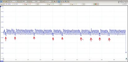
THIS Captured Diagnostic Wave Form Image CLEARLY shows the Value of performing Basic Oscilloscope Diagnostics revealing that the Mis-Fire in this Case Study had a MECHANICAL CAUSE.

Paul reasoned this problem out after seeing that the Valves of the #1 Cylinder were randomly STICKING OPEN as he could see this phenomena on the Laptop Screen PICO-Scope Signal Trace during this Clear-Flood Cranking Episode towards the very end of the linked Video:

The Red Arrows high-light the RANDOM DROP IN AMPERAGE DRAW for the Cylinder(s) with "Sticky" Valves NOT closing sufficiently to create the expected Compressive Resistance against the Starter Motor-to-Flex-Plate while turning over the Engine:

RELATIVECOMPRESSIONTEST.jpg


Once Again... PICO-Scope ...FTW!
 
Last edited:
mrrsm

Original poster
Lifetime VIP Donor
Supporting Donor
Member
Oct 22, 2015
8,246
Tampa Bay Area
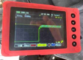
THIS One is a Short & Sweet Demo of the Following Issue:

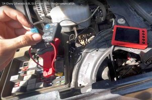
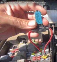
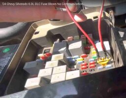
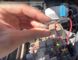
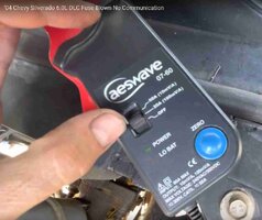
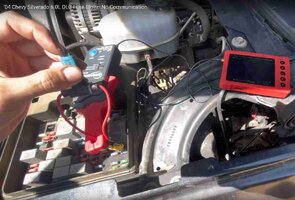
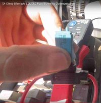
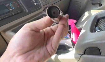
2004 Chevrolet Silverado with the 6.0L Engine Keeps Shorting Out the DLC Fuse (Lost Communication). A Closer Look into the Fuse Box revealed that the Vehicle Owner tried solving the problem by using a 25 AMP Fuse in the 15 AMP Slot for the Cigarette Lighter:

AESWAVEGEAR1.jpgAESWAVEGEAR2.jpgAESWAVEGEAR4.jpgAESWAVEGEAR3.jpgAESWAVEGEAR5.jpgAESWAVEGEAR6.jpgAESWAVEGEAR7.jpgAESWAVEGEAR8.jpgAESWAVEGEAR9.jpgAESWAVEGEAR10.jpg

The VOP (Diagnostic Dennis) used the following Gear for this investigation:

(1) An AES-Wave Palm Sized Oscilloscope with various Leads.
(2) A Low Amperage Current Clamp.
(3) A "Fuse Buddy" Loop fitted with a 15AMP Circuit Breaker.
(4) A System Wiring Diagram.
(5) A USB Charger Adapter to Replace the Old Lighter.

After replacing the Over-Sized (AMP wise) Fuse with the Fuse Buddy, the Tech Clamped the (Zeroed) Jaws of the Low Amp Clamp around the Wire Loop of the Fuse Buddy.

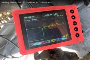
Then he set the Trigger Point on his AES-Wave "O" Scope Screen to 20 AMPs. He then pressed the Circuit Breaker Button IN... and it instantly Tripped OPEN.

The Tech viewed the On Screen Wave Form as set to the converted 37 AMPs on the Vertical Voltage Scale and set the Time Base to 20 Milliseconds to discover the behavior of the DC Voltage Trace that worked momentarily just before Tripping the Circuit Breaker at slightly more than 22 AMPs.

Knowing that the Cigarette Lighter is part of the Circuit supporting the DLC prompted the Tech to investigate the condition of the Lighter. It was Rusted, Rotted and Shorting Out internally and Drawing excessive Amperage without "Popping Out" as a result.

The Tech simply replaced Old Cigarette Lighter with a Brand New USB Charging Adapter and then re-set the 15 AMP Circuit Breaker. After pressing the Adapter inwards to activate the Circuit, it worked without tripping the 15 AMP Circuit Breaker.

He then replaced the "Fuse Buddy-Circuit Breaker" Combo with a Proper 15 AMP Fuse and with that Action, the Power and Comms on the DLC were Restored.


mrrsm

Original poster
Lifetime VIP Donor
Supporting Donor
Member
Oct 22, 2015
8,246
Tampa Bay Area
In Post #16 ... I made mention of wanting to investigate using an In Cylinder Pressure Transducer and a Four Channel, Professional Quality PICO-Scope Oscilloscope to try capturing and explaining the Known Good vs. Bad Wave Form differences and subtleties during ICPT Compression Testing.

These are matters that require careful examination and interpretation of the collected Wave Forms before coming to any firm conclusions and then acting upon such Diagnostic Results.

Admittedly... THIS portion of the use of any Oscilloscope and any ICPT (In Cylinder Pressure Transducer) Testing requires some experience and thought during this entire process.

Thankfully for us, just Today (06-22-2022) "The Man From PHAD (Crazy Ivan) from "Pine Hollow Auto Diagnostics" has a 'Repeat Customer' who owns a Jet Black 2014 GMC Sierra 1500 Truck as the subject of this inquiry.

Only recently, this same Black Sierra suffered the effects of "An Accumulation Of Errors" that lead to the Owner Over-Revving his Hopped Up 6.0L LS Motor ...and then Throwing a Rod right through the side of the Engine Block just after he Disabled The Rev Limiter in his Performance Tune:

You will NOT Believe what this 2014 Sierra Owner Did... WHAT A MAROON !!!


Well, frankly, I'm not one bit surprised that shortly afterward, a Friend of Ivan's had to Swap a Replacement Junkyard 5.3L LS Engine into this 2014 Black Sierra and that this vehicle has once again shown up at PHAD with a "Drop in Power ...Along with a Suspicious Engine Tick".

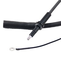
And so this SO SAD PHAD SAGA 2nd Video continues the Plot as We Peek Over Ivan's Shoulder and delve into "The Utility of Performing 'In-Cylinder Compression Tests' on a Running GM Engine Using an Oscilloscope":

 
Last edited:
mrrsm

Original poster
Lifetime VIP Donor
Supporting Donor
Member
Oct 22, 2015
8,246
Tampa Bay Area
Ooohhh Noooo!!! ... Is this yet another of Bob’s, “How About Using Your Oscilloscope…” Videos?

Yes… and NO!

THIS
Video Starts at the point where MOST of us might ‘Skip These Procedures…’ and wind up diving right in on doing some Class 2 Network Diagnostics…

BEFORE DOING THE BASICS of Using a DMM

...
and without following the OEM System Wiring Diagrams and-or using the OEM PCM-ECM Pin-Outs to...

ESTABLISH & CONFIRM POWERS & GROUNDS

...And THEN… It will be Time to Use the Oscilloscope… :>)

I LOVE the Simplicity and Diagrammatic Explanations shown in THIS particular 'British' Video because it applies UNIVERSALLY to these kinds of Diagnostics and it will Strengthen our Knowledge and Confidence as Automotive Diagnosticians:


PS... Download and Save This Video.... AND Screen Print EACH of the Explanatory Diagrams the VOP (Video Original Poster) displays here and SAVE them as well within your "Mechanic's Library".
 
Last edited:
mrrsm

Original poster
Lifetime VIP Donor
Supporting Donor
Member
Oct 22, 2015
8,246
Tampa Bay Area
If you own a 2014 Sierra or a Full Size Truck or SUV of similar Vintage and have any "No Start-Misfire" events and want to View the In Cylinder Pressure Transducer Recorded Wave Forms collected by "Crazy Ivan" The Man from PHAD (Pine Hollow Auto Diagnostics) including his Complete Case Study and R&R of a Failed Lifter in a 5.3L Swap Engine covered in Post #36, then visit THIS Link and choose the "Download ALL" Feature in the Upper Right Hand Corner of the Page:


Ivan has included THE Most Important Image in this ZIP File Set as "THE Known Good Wave Form" for use in any similar situation for better Oscilloscope Comparisons and Analysis of whatever you might encounter under similar circumstances in the future.

This information definitely belongs 'On The Shelf' of Everyone's GM Oscilloscope "Known Good" Wave Form Library:


mrrsm

Original poster
Lifetime VIP Donor
Supporting Donor
Member
Oct 22, 2015
8,246
Tampa Bay Area
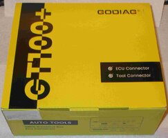
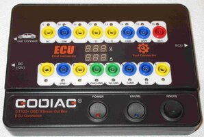
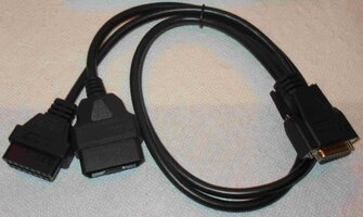
I know I've thrashed out the Topic & Imagery of using a Desk Top Breakout Box with a Switched 12 Volt Power Supply Built In recently... but in addition to using that Device for PCM Diagnostics and Programming... it can also be used IN THE VEHICLE too for hooking up to the Under-Dash DLC and directly cross-probing and sensing the various Class 2 Network Module Data Paths with any Oscilloscope or Multi-Meter.

See Post #55 and Post #56 here for the Full Details on the GODIAG GT100+ Breakout Box & Desktop Bench Probe Test Harness:


GODIAGEAR1.jpgGODIAGEAR6.jpgGODIAGEAR11.jpgGODIAGEAR12.jpgGODIAGEAR10.jpg

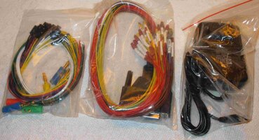
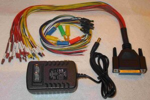
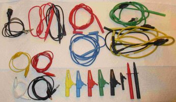
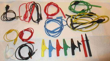
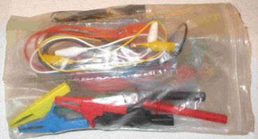
But what was missing at the time I was explaining this Amazing Tool Kit... was a Complete Snap-On Multi-Meter & Oscilloscope Probe Leads - Wire Set along with their Modular Banana and Alligator Contacts I had lucked into over on eBay.

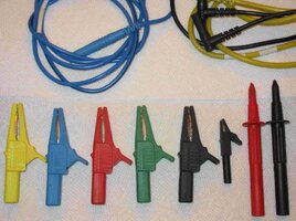
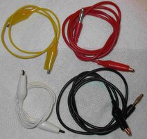
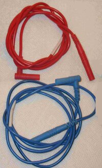
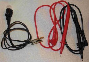
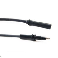
THESE are the Ones You WANT! They're all here! The Neat and Unconfused Color - Coded versions of High Quality, Flexible Silicone Leads with Gold and-or Chrome Plated Contacts and "Alligator Clips" that REALLY behave like REAL Alligators do by Clamping and Holding TIGHT and NOT allowing the Test Leads to Pop Off any Contact Points at the Slightest Tug when working away Under the Hood! No Guess Work Either as to Which Probe Leads are attached to What Channel(s) on Your 'Scope!!!

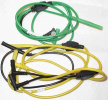
The Yellow and Green (Red and Blue, Singly) Primary Leads are 5 Feet Long and have Multiple Ground Sub-Leads with Right Angle Banana Fittings allow for "Piggy-Backing" additional leads or probes into them at One Go.

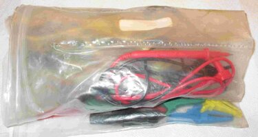
It has taken a month or so for this Full Kit to finally arrive from England. However, it was (WWTW) Well Worth The Wait since it arrived here as a Used Kit... but is just as COMPLETE (With Even MORE Goodies included ) as the ones that Snap-On sells as Brand New for over $250.00 from off the back of any Snap-On Dealer Truck... Stateside.

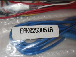
So here is what I got for my $50.00 'American' in this Snap-On Durable Zip-Lock Plastic EAK0253B51A Roll Up Kit:

SNAPONPROBEKIT1.jpgSNAPONPROBEKIT2.jpgSNAPONPROBEKIT3.jpgSNAPONPROBEKIT4.jpgSNAPONPROBEKIT5.jpgSNAPONPROBEKIT6.jpgSNAPONPROBEKIT6B.jpgSNAPONPROBEKIT7.jpgSNAPONPROBEKIT8.jpg
SNAPONPROBEKIT9.jpg
 
Last edited:
mrrsm

Original poster
Lifetime VIP Donor
Supporting Donor
Member
Oct 22, 2015
8,246
Tampa Bay Area
In this Quest to get The Best & Most Affordable, High Functionality Oscilloscopes Available...

YOUR VIGILANCE WILL PAY OFF!!!


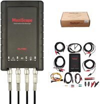
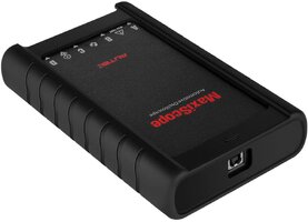
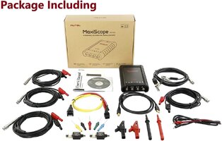
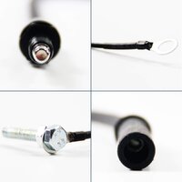
I've had my eye on THIS Professional Grade Autel Maxi-Scope Model# MP-408 USB Oscilloscope for some time now because it supports Four (4) BNC Channels and is up-rated from 8 Bit to a 12 Bit Vertical Sample Rate.

THAT means a 16Xs improvement over the 8 Bit Sampling rate for MUCH Better On Screen Precision Signal Resolution... Say for an In-Cylinder Compression Test using a 300 PSI Pressure Transducer ...and trying to Resolve Subtle Changes in the Wave Form for a Better Compression Test Conditions Diagnosis:

AUTELMAXISCOPEMP40800.jpgAUTELMAXISCOPEMP4080.jpgAUTELMAXISCOPEMP408KIT.jpg


However... This Problem ALWAYS comes in Three Parts:

(1) PRICE
(2) PRICE
(3) PRICE

And after visiting Amazon quite frequently (...almost DAILY)... THIS is what they are ALWAYS asking for in order to get an Autel MP-408 Maxi-Scope along with its Basic Kit Hardware:

AUTELMAXISCOPEMP408A4.jpg

But... "NEVER SAY DIE..." as the Old Saying Goes... and it followed on that today, I ventured *** Once More Unto The Breach *** heading right back to eBay to check on things...

LO And BEHOLD... There WAS an "OPEN BOX" Autel Maxi-Scope Model# MP-408 Kit on offer with an additional 10% Off the Lowered Sales Price for only $238.51

AUTELMAXISCOPEMP408B.jpg

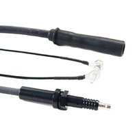
WHAT? ...Well Damn, Dog...!!! THAT'S Almost $200.00 LESS than the prevailing Retail Prices ANYWHERE!!! So... Yeah... You can just BET that I Pounded That "Buy It NOW" Button... REAL HARD:

AUTELMAXISCOPEMP408C.jpgAUTELMAXISCOPEMP408D.jpg


And... For us all to get a Better Idea of, "What's ALL THE FUSS About?"...Have a Look at THIS Excellent Unboxing and Basic Performance Overview from another person who is just as appreciative of what Autel brings along with this Basic Kit as a High Quality Automotive Oscilloscope:

The Autel Maxi-Scope Model# MP-408:


...and in a "'$60.00 vs. $4,500.00 Auto Scope Shoot-Out" between Two Different PICO-Scopes, One Hantek Scope and THIS Autel Scope... you can see how this $500.00 Range Scope Performs in Wave Form and Measurement Comparisons... versus all of the others:


Attachments

  • autel-maxiscope-mp408-user-manual.pdf
    2.5 MB · Views: 0
Last edited:
  • Like
  • Love
Reactions: 808 and budwich
Forum Statistics

Threads
23,705
Posts
642,339
Members
19,204
Latest member
jozene

Members Online