LED Mod Thread

mrphoenix80

Member
Jan 1, 2013
251
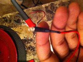
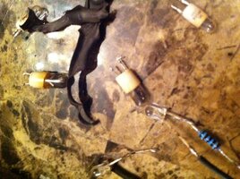
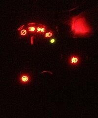
I would have to say you can. While I have not personally had that radio apart I can't believe it would be impossible. The hardest thing is getting the polarities correct. I am doing my cd/cassette radio in red LEDs today! But I dont find a dash light circuit listed in the schematics so I have to go and measure the circuits with a dvom to make sure I get it right.

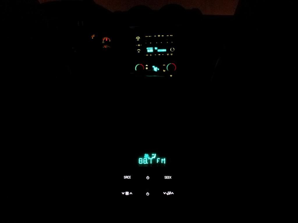
Just one question. Did your lights all go out at once or 1 at a time? I dont like the odds that 8 to 10 bulbs all failed together. So if it was all at once I would be checking to make sure that the illumination circuit to the radio is ok.

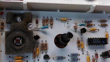
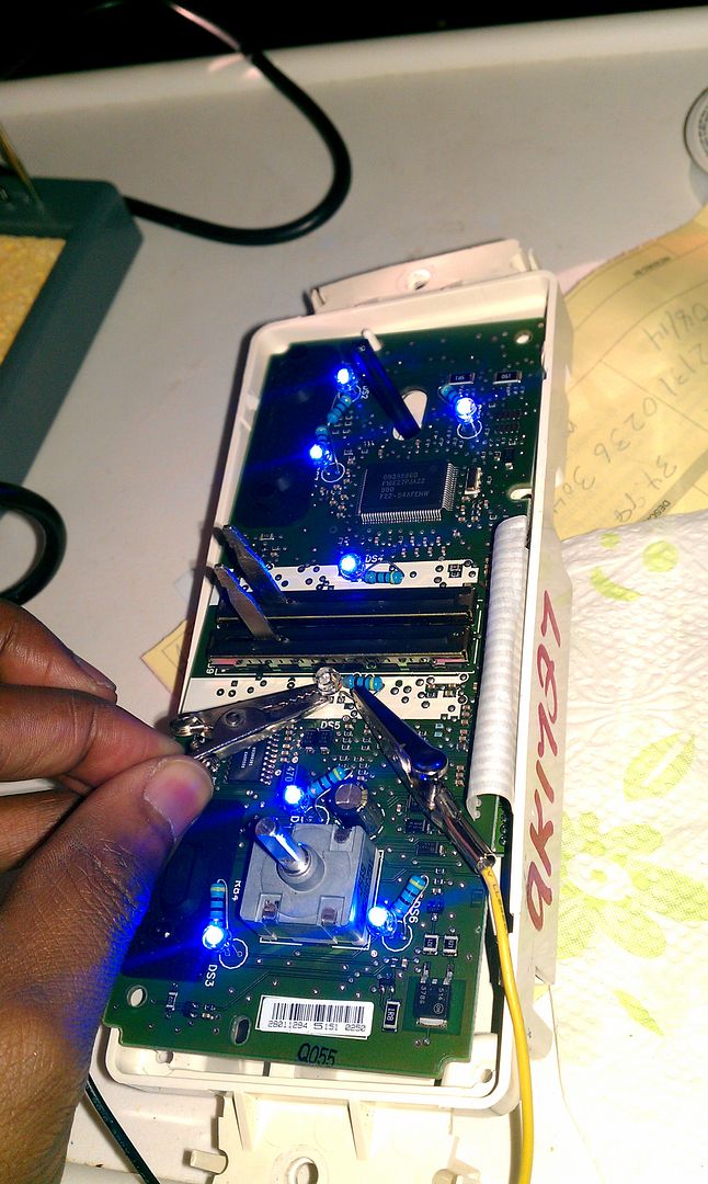
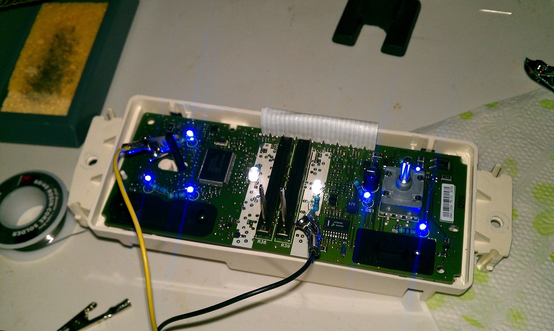
And yes I will post my pics when I get the center stack done. I work for a dealer and have been thinking about this for several weeks. So when an item has to be replaced a have saved the old ones so I can play. And after having 2 manual heater control heads apart I found the circuit boards are totally different. So is this the reason some are having issues with the polarities that where posted earlier? And because I also got an old cluster to take apart I found in it that the shafts pulled out of the motors when I removed the needles. So I am waiting until I get the new motors before I take mine apart to do the LED swap.
 

Blckshdw

Original poster
Moderator
Nov 20, 2011
10,686
Tampa Bay Area, FL
mrphoenix80 said:
...after having 2 manual heater control heads apart I found the circuit boards are totally different. So is this the reason some are having issues with the polarities that where posted earlier? ...

Well that certainly makes me feel better. I thought I was losing my mind, cuz I KNOW I checked the polarities a few times before posting that pic a while back.
 

mrphoenix80

Member
Jan 1, 2013
251
jeffro312 said:
Yea not sure if they all went out at once when I purchased truck they were out. How would I go about checking any ideas

When I look into it it shows the illumination control postive feed on pin B4 of the large connector and ground on pin B5. The B pins are on the bottom row. B4 is a brn/wht wire and B5 is black. Now for the bad part it calls this out for RPO UQA (bose?) and early production only with no other options listed. So this my not help you. I have to look at my truck and see how the radio gets it signal for illumination. Could it be that the radio gets the ilumination info from CLASSII communication? I hope not because this will make the job of finding the polarties harder. The only other thing you can do is dive in and hope the previous onwer decided it was too expensive/difficult to fix and just let them go out one at a time.
 

mrphoenix80

Member
Jan 1, 2013
251
Blckshdw said:
Well that certainly makes me feel better. I thought I was losing my mind, cuz I KNOW I checked the polarities a few times before posting that pic a while back.

I have not had time to map the polarities yet for the second controller but here are some shots so you what I mean.
 

Attachments

  • IMG_0071.JPG
    IMG_0071.JPG
    59.6 KB · Views: 238
  • IMG_0078.JPG
    IMG_0078.JPG
    59.2 KB · Views: 235
  • Like
Reactions: CaptainKD

Blckshdw

Original poster
Moderator
Nov 20, 2011
10,686
Tampa Bay Area, FL
mrphoenix80 said:
I have not had time to map the polarities yet for the second controller but here are some shots so you what I mean.

:yes: 
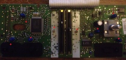
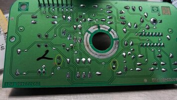
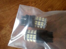
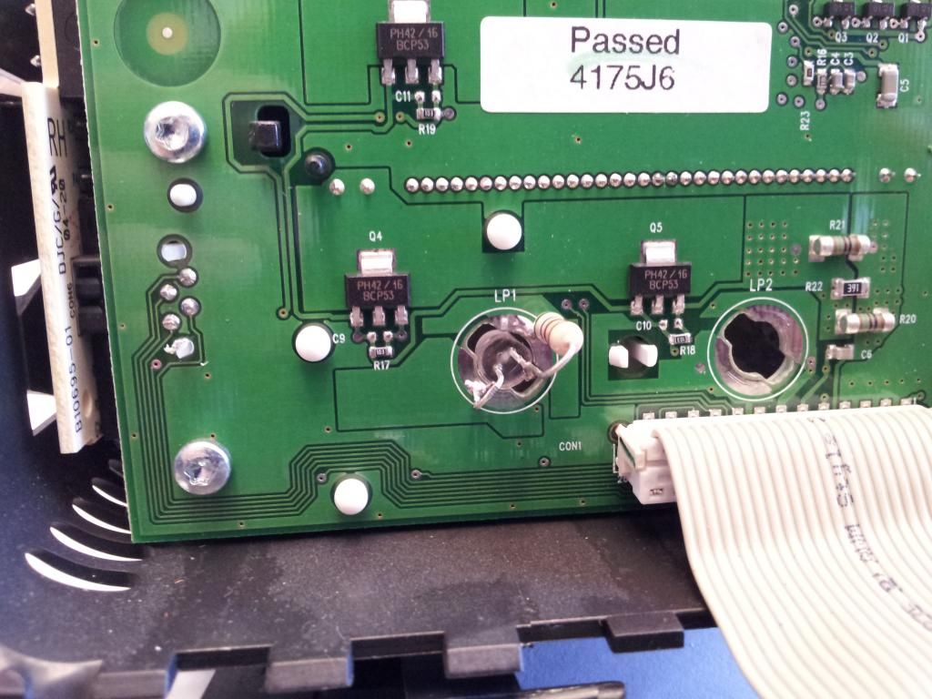
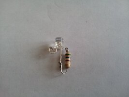
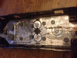
The bottom one is what I have, same polarity findings too. If the guys who had the issues with different polarities have the top one, that could explain everything.
 

mrphoenix80

Member
Jan 1, 2013
251
Did any of you guys that did the LEDS in the driver and passesnger door switches have any trouble getting the light to show up? My leds are on but the switches do not light up so I can see them even in the dark. I tried adjusting the hieght of the LED and adding reflective material to the board that carries the light and still nothing. THE leds I am using are 5mm red 12,000mcd. They light up good every place else I have used them just not in the window switches.:confused:
Oh well tomorrow is another day.
 

Blckshdw

Original poster
Moderator
Nov 20, 2011
10,686
Tampa Bay Area, FL
The important part is WHERE you mounted your LEDs? Did you put them in the factory locations? Since LEDs don't emit much light sideways, you'll get poor output if you used 1 or 2 of them in the stock locations. Most of us (at least from what I've seen) drill holes in that clear plastic piece, put an LED under each button, and run contact wires back to the contact pads.
 

mrphoenix80

Member
Jan 1, 2013
251
When I looked at your shots I saw the wires and wondered why you did that. It makes sense to me now. Unfortunatly I have to postpone doing them a friend lost her house last night. No one hurt but total loss of property.:frown: 
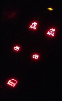
And that is more important than cool looking window switches.:yes:
 

mrphoenix80

Member
Jan 1, 2013
251
Ok so I got the left front switch done and it looks great now that I have the Leds placed correctly.
So heres what I have so far.
 

Attachments

  • IMG_0081.JPG
    IMG_0081.JPG
    40.7 KB · Views: 229
  • IMG_0082.JPG
    IMG_0082.JPG
    17.9 KB · Views: 226
  • IMG_0088.JPG
    IMG_0088.JPG
    16.9 KB · Views: 227

jeffro312

Member
Oct 4, 2012
442
East Haven,Ct
mrphoenix80 said:
It's all red the camera does make the colors true. There is a brightness difference in the radio buttons but I will live with it. Hopefully I can do the cluster tomorrow night! The stepper motors are on the way and should be here tomorrow.

Maybe u can help me. What tells radio lights to light? When purchased my truck. All radio lights didn't work possible all blown or something else.....I also get the cal error on screen but radio functions properly
 

mrphoenix80

Member
Jan 1, 2013
251
Early 04's only with the bose system use a illumination feed pin b5 on the large connector (brn/wht wire) all others are CLASSII data commanded because the radio is a computer module. What is "early production"? I have no idea what the break point is. So pull the radio and see if it has the wire. If not you're that far already, open the radio and check the bulbs. It only takes simple tools and about 5min more to remove the face and then you check the bulbs with a 9v battery(at least thats how I did it).

The "CAL ERR" message on the radio means that something is not setup correctly. Most likely caused by an RPO code overlooked when programing the radio. Most likely you will have to get the radio reprogramed to correct this.

No cluster mods tonight:no: I forgot about the holiday!:hissyfit:

Thank you all for the comments
 

Default User

Member
Dec 19, 2012
71
Got these in the mail yesterday

9anade5u.jpg


Huge difference over the standard OEM Clear bulbs.

y3u4ahug.jpg


uvate4an.jpg


Not a huge custom mod per say - but did a lot of research to keep my dimming feature.

The older-style LED bulb will allow factory dome light dimming feature - SMD LED bulbs will not.
 
  • Like
Reactions: CaptainKD

mrphoenix80

Member
Jan 1, 2013
251
So I finally got my IPC done, sort of.:frown: It seems that the LEDs around the speedo and tach don't give off good light.
Did any of you add exrta LEDs to get the desired effect? I mean it looks ok when dark dark out but at twilight no so much.
Maybe I will play a bit more with my scrap cluster and see what I can find out.
 

Attachments

  • IMG_0098.jpg
    IMG_0098.jpg
    26.3 KB · Views: 25

Blckshdw

Original poster
Moderator
Nov 20, 2011
10,686
Tampa Bay Area, FL
I think most of us have the same issue. I tried mounting mine as close to the board as I could, but on the back of the cluster face, there are some big clear plastic ramp-like things that go over the bulbs. I think those make the hot spots worse than they'd normally be. :hissyfit:
 

mrphoenix80

Member
Jan 1, 2013
251
I am glad I have access to scrap parts that I can play with! You should see my desk right now. I got 2 radios, an auto hvac controller, a manual hvac controller, and a cluster laying here. Not to mention a CHMSL from an H3 and assorted turn signal boards I rescued/liberated from broken side mirrors. I had installed my 5mm 12000mcd red LEDs and they did not even begin to light the cluster. So I ended up taking apart 2 of the turn signal boards from fullsize truck mirrors. I know those LEDs are bright so I put them in the cluster. They do OK but i would like it brighter. So I shall continue to play.:yes:

Oh by the way I think I Took out the driver for illumination on the DDM. I MAY have overloaded it:redface:
 

Blckshdw

Original poster
Moderator
Nov 20, 2011
10,686
Tampa Bay Area, FL
mrphoenix80 said:
...Oh by the way I think I Took out the driver for illumination on the DDM. I MAY have overloaded it:redface:

Unless you shorted the bulb sockets on the board, I'd guess you maybe have a broken solder joint (although I don't know how you've got your LEDs wired up in there), or maybe blew your LEDs since they take such little voltage. Care to show some pics?
 

mrphoenix80

Member
Jan 1, 2013
251
Because I had all ready soldered my resistors to the LEDs I just used those and wired all 5 in parallel. Then to top it off I hooked them all to the same socket. So if I am thinking right 20mA x 5 = 100mA where 1 bulb is supposed to be. I rarely break solder joints so that is why I think I took out the driver. However I was to lazy last night to remove the switch and check. It worked good for a day.
 

Blckshdw

Original poster
Moderator
Nov 20, 2011
10,686
Tampa Bay Area, FL
Those door modules ARE a royal pain to dismantle. I hated when I went back to the truck to install them after getting them right, and then one of the LEDs was a little bit off so a button looked dimmer than the rest. :mad:
 

Blckshdw

Original poster
Moderator
Nov 20, 2011
10,686
Tampa Bay Area, FL
One of my HVAC LEDs was acting up and died today. I didn't use much solder on them, so I thought it was just a solder joint gone bad... Nope. I applied power directly to the LED/resistor's legs, and all of the other ones lit up instead :confused:

IMAG0515_zpsb30f23de.jpg


After seeing someone else who did their HVAC, I decided to replace the 2 temp slider LEDs with white ones instead of blue, so the red shows up at night. The flat tops are considerably brighter than the straw hats, something tells me I'm gonna be pulling the rest of the blue ones out to replace with flat tops at some point.

IMAG0516_zps3f8de2e0.jpg


Installed, and looking much better. :yes:

IMAG0518_zps6ea77309.jpg
 
  • Like
Reactions: CaptainKD

mrphoenix80

Member
Jan 1, 2013
251
mrphoenix80 said:
I rarely break solder joints so that is why I think I took out the driver. .

:redface:So I umm got a look at my DDM tonight and it was a broken solder joint:redface:
See what arrogance gets you. But as long as I was in there I rewired it so its in series now and it works good.
 

Attachments

  • IMG_0101.JPG
    IMG_0101.JPG
    84.1 KB · Views: 243

Blckshdw

Original poster
Moderator
Nov 20, 2011
10,686
Tampa Bay Area, FL
mrphoenix80 said:
:redface:So I umm got a look at my DDM tonight and it was a broken solder joint:redface:
See what arrogance gets you. But as long as I was in there I rewired it so its in series now and it works good.

At least broken joints are easier to fix, than fried/broken traces... :rolleyes: 
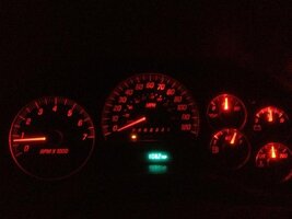
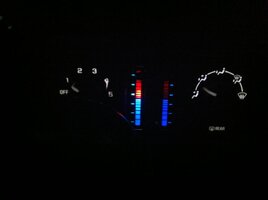
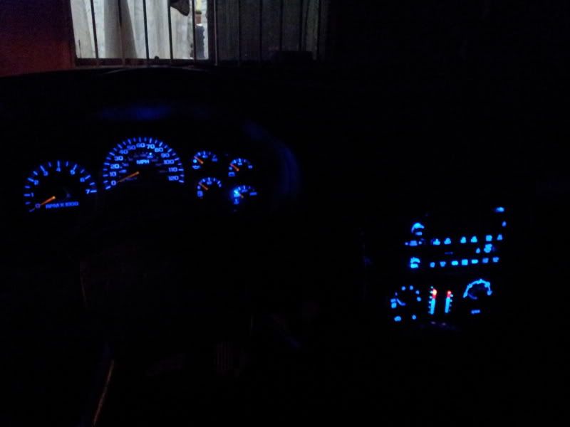
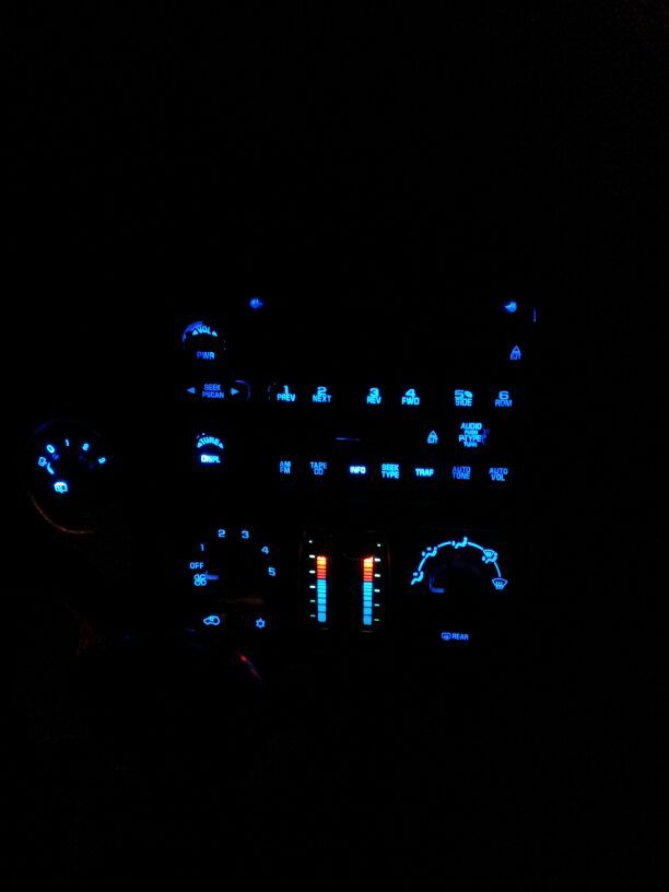
Although due to a fried trace, I found a convenient reason to upgrade my cluster to a DIC model :biggrin:

NinjuhhNutz said:
That looks GOOOOODDDDD...the one thing I didn't like about the led swap was that the red didn't show up at night...looks great now :thumbsup:

Thanks Chris :iagree: 
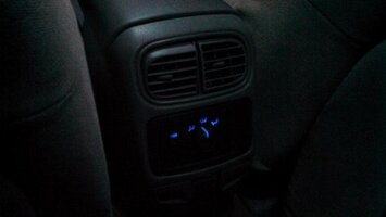
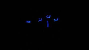
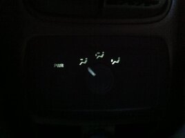
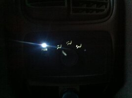
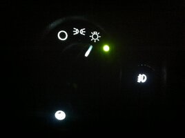
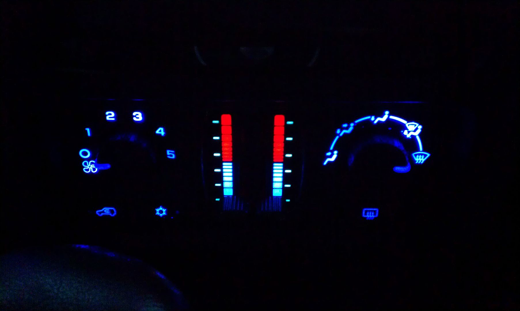
it looks much better now. I suppose I should take out the rear module and do the same, but that only has 2 LEDs on the sides, so I'd have to add one to the middle... Ehh, since there's rarely anyone back there, I think I'll skip that. :yes:
 

Conner299

Member
Jan 16, 2013
279
Since I hadn't seen anything posted on this unit, yet, here is my contribution. I figured I would attack this unit first for a couple of reasons. First, it was easy to get out, and didn't require ripping apart the dash. Second, a good first attempt at the LED's, especially since I had never soldered anything, before today. Third, if I screwed up, The module is pretty cheap to replace.
The LED's and resistors I used were the same as the ones used in the posts by Blckshdw. The rear unit pops out pretty easily with just a screw driver. There are two bolts, at opposing corners, that need to come out first. After that, it comes apart more easily than I figured it would. I figured I would have trouble with figuring out the positive and negative polarities for the LED's. I said a prayer and hoped for the best. Luckily I got it right, first try. Hope this helps out some people.
 

Attachments

  • IMG_20130203_160752_893.jpg
    IMG_20130203_160752_893.jpg
    87.8 KB · Views: 35
  • IMG_20130203_160557_562.jpg
    IMG_20130203_160557_562.jpg
    70.1 KB · Views: 43
  • IMG_20130203_160631_161.jpg
    IMG_20130203_160631_161.jpg
    97 KB · Views: 46
  • IMG_20130203_200523_474.jpg
    IMG_20130203_200523_474.jpg
    48.3 KB · Views: 40
  • IMG_20130203_200511_475.jpg
    IMG_20130203_200511_475.jpg
    12.3 KB · Views: 36

mrphoenix80

Member
Jan 1, 2013
251
Conner299 said:
Um... Im still learning what parallel and series circuits are.
I noticed the traces the LED's were on was pretty much a single, dead-end line.

Ok the easiest wat to explain this is. A series circuit connects all the loads(LEDS in this case) end to end, or + to - to + and so on. As you can see both from your board and the photo of the guts of my window switch in a earlier post. In a series circuit the loads add up. Meaning your resistance is more than needed in your control head. You only need one resistor to control both LEDs. Google a led calculator for series circuits and you will see that you need less resistance to get the required voltage drop.
So by changing your resistors your LEDs will be brighter. IF you are happy with it leave it be, but if you want it brighter change it.

Parallel circuits basically tie all the positives together and all the grounds also. Meaning you get full power to all the LEDs in the circuit. So you need a different resistance value for those(the ones Blckshdw uses). I am pretty sure all the rest of the modules in the truck use the parallel lighting circuits.

The reason I did my window switches in series is because in a series circuit the amperage is lower(24mA). Because the current is limited by the lowest amperage component? This is where I get a bit fuzzy. But the current across each LED is added when in parallel. So the same 5 LEDs will use (24mA x 5) 120mA. If my math is correct. The illumination driver in the door switch is very small, and I dont know if it can handle that kind of draw.

I did a quick search and found a couple images to help understand.
 

Attachments

  • Parallel-Circuits.jpg
    Parallel-Circuits.jpg
    32 KB · Views: 193
  • seriesCircuit.jpg
    seriesCircuit.jpg
    27.3 KB · Views: 194

djez015

Member
Jan 28, 2013
67
ok so i redid my frt turn signal/parking light leds and with resisters i get no hyper flash but i still dont have led parking light for the front , the fuse is blown and it keeps blowing every time i change it and turn on my lights ..... the only thing i can think of is the leds dont support both
 

djez015

Member
Jan 28, 2013
67
also all my other led swaps worked out great pics coming soon want to wait till every thing gets here and installed so far new headlights in dome (green) leds in and a rear 16 led (white) for when i have to pull out tools...still to come are the mini pre wired leds to re do my switch panels and foot well leds
 

Short Bus

Member
Dec 2, 2011
1,906
djez015 said:
ok so i redid my frt turn signal/parking light leds and with resisters i get no hyper flash but i still dont have led parking light for the front , the fuse is blown and it keeps blowing every time i change it and turn on my lights ..... the only thing i can think of is the leds dont support both

Some of the 02s are wired for SRCK in the front turn signal/parking light, and that's what it sounds like is going on with your truck. You need to do a little rewiring. If the fuse is OK with parking lights, but blows with turns reverse the + and - on the turns.

This pic is for modding the tail light board, but if you look at the top socket you can see the difference between standard and SRCK.

Untitled.jpg
 

djez015

Member
Jan 28, 2013
67
oh wow thats strange but it looks like im going to have to go into the socket it self and move things around and on another note from this diagram it looks like the newer TBs have 2 lights as parking lights instead of the one might have to redo the tails too lol
 

Blckshdw

Original poster
Moderator
Nov 20, 2011
10,686
Tampa Bay Area, FL
djez015 said:
oh wow thats strange but it looks like im going to have to go into the socket it self and move things around and on another note from this diagram it looks like the newer TBs have 2 lights as parking lights instead of the one might have to redo the tails too lol

Close, but not quite... A bunch of guys modded their tail light boards to make the 2 bulbs come on as parking lights. There's a couple of threads on it if you want some light reading. But :yes: you should let your mod bug run wild. It's a healthy thing to do from time to time. :biggrin:
 

DFWWIZ

Member
Dec 5, 2011
516
djez015 said:
ok so i redid my frt turn signal/parking light leds and with resisters i get no hyper flash but i still dont have led parking light for the front , the fuse is blown and it keeps blowing every time i change it and turn on my lights ..... the only thing i can think of is the leds dont support both

I agree with short bus, it seems you may have SRCK in the front as well. That would be why the fuse is blown. I actually do have SRCK CREE white/amber switchbacks-just not much of a market for them. Also I have sets of new boards for $25/pr if people need them.
 

Short Bus

Member
Dec 2, 2011
1,906
djez015 said:
oh wow thats strange but it looks like im going to have to go into the socket it self and move things around and on another note from this diagram it looks like the newer TBs have 2 lights as parking lights instead of the one might have to redo the tails too lol

Or you might be able to cut and splice the wires or you can get new sockets for < $10 each. If your a cheap SOB like me you'll see if you can make hat you have work, like you said.

Blckshdw said:
Close, but not quite... A bunch of guys modded their tail light boards to make the 2 bulbs come on as parking lights. There's a couple of threads on it if you want some light reading. But :yes: you should let your mod bug run wild. It's a healthy thing to do from time to time. :biggrin:

Like Blckshdw said, that pic is for modding the tail boards. I just used it to show SRCK vs. non-SRCK
 

djez015

Member
Jan 28, 2013
67
Short Bus said:
Or you might be able to cut and splice the wires or you can get new sockets for < $10 each. If your a cheap SOB like me you'll see if you can make hat you have work, like you said.


Like Blckshdw said, that pic is for modding the tail boards. I just used it to show SRCK vs. non-SRCK

what kind of sockets ??? should i look for a newer year socket ?


but it also from the looks like i can order leds that are re configured for srck
 

Short Bus

Member
Dec 2, 2011
1,906
djez015 said:
what kind of sockets ??? should i look for a newer year socket ?


but it also from the looks like i can order leds that are re configured for srck

Ya you can get them from a newer TB or any auto parts store. It's normally cheaper to replace the sockets + there's more options if you stay away from SRCK.

Here's some cheap sockets on ebay.

[EBAY]280958247112[/EBAY]

and a set that ships from the US

[EBAY]150992156601[/EBAY]
 

DFWWIZ

Member
Dec 5, 2011
516
mrphoenix80 said:
SRCK or Non SRCK???


edit: nevermind I just looked. Modified for Non SRCK

Un modified SRCK for $25. I only modify them to NON SRCK if someone wants them that way.
 

djez015

Member
Jan 28, 2013
67
View attachment 26323

sooo glad to have my leds working right just picked up some cheap srck leds and fixed my problems with the resistors tomarrow ill prob change my hids to 6k and move my 8k set to my high beams
 

Attachments

  • hids.jpg
    hids.jpg
    95.5 KB · Views: 54

djez015

Member
Jan 28, 2013
67
Did some led mods today I ordered some ebay pre-wired leds 3mm the resistors where already wired in I did the rear hvac controls the headlight switch and part of my main hvac controls


View attachment 26371
View attachment 26372
pre wired leds 3mm about the same size of the oem bulbs I should of went bigger


View attachment 26369

View attachment 26370

View attachment 26373

View attachment 26374
I was tired after I got to this one after the 1st try the pass. side led didn't come on then bought it in ,for some reason that side was not getting power so i tapped off the other led ran wire put it back together then the driver side went out :mad: took it apart again realized i broke the driver side led putting it back together, after re doing the leds again for a 3rd time i had both sides working but the driver side was brighter :hissyfit: sooooooo. now my plan is tomorrow at my shop I have a roll of led strip I can custom cut that I think I am just going to use for slide controls then solder in the rest of the leds for hvac controls


also I picked up some of the door projectors leds for all 4 doors taped into the doom lights for each door came out great

View attachment 26375
 

Attachments

  • get-attachment.jpg
    get-attachment.jpg
    35.9 KB · Views: 46
  • get-attachment (1).jpg
    get-attachment (1).jpg
    48.5 KB · Views: 47
  • get-attachment (4).jpg
    get-attachment (4).jpg
    97.2 KB · Views: 49
  • get-attachment (3).jpg
    get-attachment (3).jpg
    96.2 KB · Views: 47
  • get-attachment (6).jpg
    get-attachment (6).jpg
    35.9 KB · Views: 48
  • get-attachment (2).jpg
    get-attachment (2).jpg
    23 KB · Views: 50
  • get-attachment (5).jpg
    get-attachment (5).jpg
    53.4 KB · Views: 53
  • Like
Reactions: CaptainKD

bluenvoyerob

Member
Jan 7, 2013
7
I recently bought some LEDs... 5mm flat top white 20000 mcd LEDS @ 25. Today I was only going to pull the rear HVAC control to plan my first mod on this truck. When taking it apart, a bulb filament broke....so onward I went with the mod, haha.

BEFORE...
View attachment 26490

AFTER...
View attachment 26489

View attachment 26491

20130223_165129.jpg


^ Halfway done here! As pictured, the positive pad is on the left for each socket.

20130223_183916.jpg


^ A picture of the rest of the truck, still rocking old bulbs (and a couple burnt out ones).
 

Attachments

  • 20130223_183841.jpg
    20130223_183841.jpg
    22.4 KB · Views: 36
  • HVACRearadjustedbeforecopy.jpg
    HVACRearadjustedbeforecopy.jpg
    23.1 KB · Views: 34
  • 20130223_164521.jpg
    20130223_164521.jpg
    49.2 KB · Views: 42

Forum Statistics

Threads
23,347
Posts
638,208
Members
18,555
Latest member
YSB