LED Mod Thread

Mektek

Member
May 2, 2017
661
FL
Some were too bright so I attenuated them by blacking them out with a black marker. Even completely blacked out, enough light gets through. Suggest you try a little at a time. I'm lucky in that I have a spare connector and able to power up the lights. I turned off the lights in the kitchen before calling it good. You could probably do the same using small connectors to the pins.

I used a higher value resistor to set the brightness. When the led was pulling 20ma it was too bright - a larger resistor dropped the current to 10ma and the brightness was perfect.
 

Blckshdw

Original poster
Moderator
Nov 20, 2011
10,747
Tampa Bay Area, FL
Does anyone have the polarity diagram for an auto hvac?Will be doing my dads Yukon by the weekend! Thanks

This can be your assignment for this weekend. You can either use a meter to test for polarity while the module is plugged into the vehicle, or use a resistor soldered to an LED, since it'll only light up when the polarity is correct. Record your findings, and post them here for future members. :thumbsup:
 

djthumper

Administrator
Nov 20, 2011
14,956
North Las Vegas
This can be your assignment for this weekend. You can either use a meter to test for polarity while the module is plugged into the vehicle, or use a resistor soldered to an LED, since it'll only light up when the polarity is correct. Record your findings, and post them here for future members. :thumbsup:
Also you may want to start a full sized thread for LED mods. Or we could just start a new one in the general forum for all and point back to this one. This thread is getting quite large.
 

Blckshdw

Original poster
Moderator
Nov 20, 2011
10,747
Tampa Bay Area, FL
Mar 30, 2016
1,465
KSA
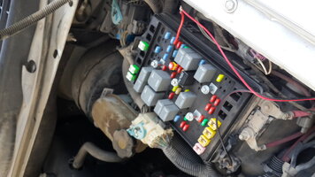
I am facing a weird issue when trying to wire up my DRL strips. I have them wired as below with red being positive and black negative. When I have them as pictured below nothing occurs. However when I switch the red and black the strips work until the ignition is turned on! Any ideas, I'm stumped 😒

20180418_172930.jpg
 

Blckshdw

Original poster
Moderator
Nov 20, 2011
10,747
Tampa Bay Area, FL
I am facing a weird issue when trying to wire up my DRL strips. I have them wired as below with red being positive and black negative. When I have them as pictured below nothing occurs. However when I switch the red and black the strips work until the ignition is turned on! Any ideas, I'm stumped 😒

The post you connected the black wire to is not a ground, that's your problem. It's supposed to be used to supply accessory power to a trailer. Your current circuit, when the wires are reversed, is using your ignition source as ground, but when you turn the key on, you have 12V on both wires, so no go...

You should have a factory fender ground just to the right of the mega fuse, in this pic. Piggy back your ground connection there, and things will work properly.
 
Mar 30, 2016
1,465
KSA
The post you connected the black wire to is not a ground, that's your problem. It's supposed to be used to supply accessory power to a trailer. Your current circuit, when the wires are reversed, is using your ignition source as ground, but when you turn the key on, you have 12V on both wires, so no go...

You should have a factory fender ground just to the right of the mega fuse, in this pic. Piggy back your ground connection there, and things will work properly.

Thank you!! I thought I was losing it! I wanted to move the ground to there, but I didn't have the right size bracket to open it. Will get back tmrw with more and what I've been working on this week 😊
 

Blckshdw

Original poster
Moderator
Nov 20, 2011
10,747
Tampa Bay Area, FL
I've messed around with putting LEDs in my headlights a couple of different ways. Heat will shorten their lifespan considerably, so you may want to periodically check the strips after you've run this setup for a bit. I expect the LEDs in closer proximity to the projector to fail first. :mad:
 
  • Like
Reactions: $ Khalid ! 9130

Sparky

Member
Dec 4, 2011
12,927
The ones I used in mine worked fine for the entire time I had them (except one diode did get a little dimmer than all the rest), but they were down in place of the factory turn signal area so thermally insulated from the projectors, and were stuck to an aluminum plate that acted as a large heatsink.
 

Blckshdw

Original poster
Moderator
Nov 20, 2011
10,747
Tampa Bay Area, FL
The ones I used in mine worked fine for the entire time I had them (except one diode did get a little dimmer than all the rest), but they were down in place of the factory turn signal area so thermally insulated from the projectors, and were stuck to an aluminum plate that acted as a large heatsink.

:iagree: When I had the switchback strips as turn signals on the bottom and sides, those lasted until I sold the headlights as well. They were mounted to strips of leftover acrylic. But the eyebrows and demon eyes I've tried didn't have such luck. The demon eyes on the current retro lasted longer, as I had them on front of the foreground limited of the projector, so they weren't in direct HID exposure, but they did get the ambient heat all the same. :frown:
 

BuffettTruck

Member
May 2, 2018
96
Florida
A question about LEDs. I have been trying for an aqua/turquoise/ice blue color in my interior. Problem is, any of those colors seems to mean something different depending on who you get the LEDs from. When I went to electrical school, I learned how LEDs worked, but that was about it. In the bit of reading I have been doing, I get the impression that I need to be looking at the 'wavelength' rating of the LEDs and start matching that if I want my colors to be uniform. Is this correct?
 

Blckshdw

Original poster
Moderator
Nov 20, 2011
10,747
Tampa Bay Area, FL
I have been trying for an aqua/turquoise/ice blue color in my interior.

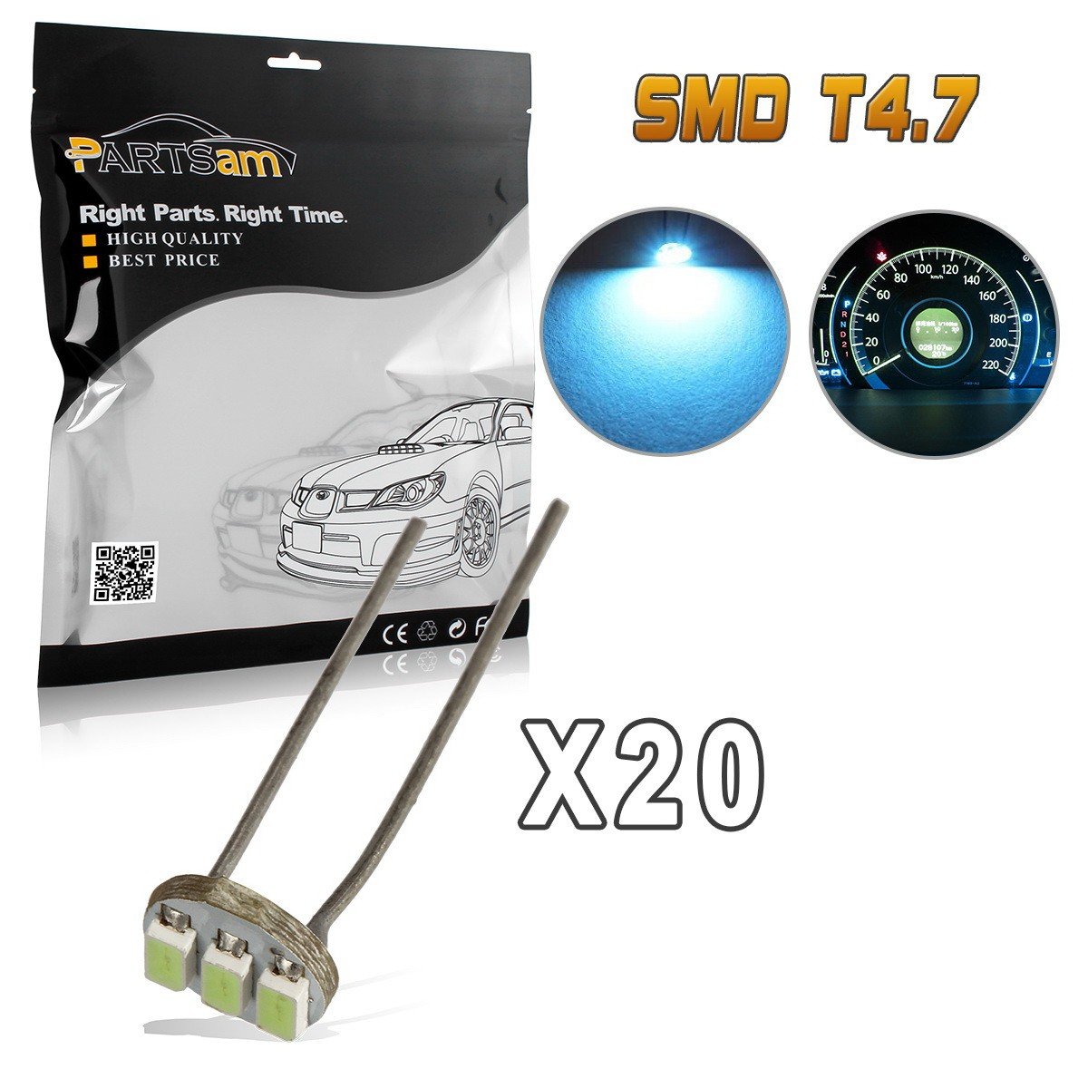
I recommended these to one of our local members when doing an LED swap with the steering wheel buttons, and eventually the dash too, and they turned out really well for that ice blue color. They are pretty bright. When I made the switch to this style, over your standard 5mm flat top LED, I had to change out all of them due to such a high difference in light output. (I don't regret it :cool:)

https://www.amazon.com/dp/B011E8T9G2/?tag=gmtnation-20

715RbKQQ7VL._SL1200_.jpg[\img]
715RbKQQ7VL._SL1200_.jpg
 

BuffettTruck

Member
May 2, 2018
96
Florida
Those are actually what I used for my dash cluster. I also started to put them into my front HVAC controller, but when checking polarity on one of the leds, I made a bonehead mistake and one of the leads got bent and touched the other one. Burned out a nice 5 inch section of the circuit, so now only the center two work and I need to order a new/used circuit board or find one at my junkyard. Luckily only the illumination circuit was affected. The above were too bright for the HVAC controller anyways, so I am going to order some softer ones in the same wavelength.

Then I ordered some 'Ice Blue' 194's for my map lights and they were a bit deeper blue. I have found another set of Ice Blue 194s that are a closer match.

https://www.amazon.com/gp/product/B01MUBHAVC/?tag=gmtnation-20

The only light I have left to swap and match is the cargo light.
 

Sparky

Member
Dec 4, 2011
12,927
You could just run little jumper wires. Sometimes the factory traces fail anyway.
 
  • Like
Reactions: Blckshdw

Blckshdw

Original poster
Moderator
Nov 20, 2011
10,747
Tampa Bay Area, FL
:iagree: I have messed up my HVAC controller from repeated (de)soldering episodes. Got to the point where only the slider light pads work normally. Got a bunch of LED strip connectors, and ran jumpers between them. Used double sided tape to keep them in place. Works great.

This is from a few pages back.

Time to revive this dead thread! After retrofitting the 4.7mm SMD LEDs into all of my dash modules, I really screwed up my HVAC controller somehow. Not sure if I scorched some traces, or lifted some pads or something, but for whatever reason, the LEDs under the dials would not light up in the truck, and on the test bench, when maxed out at 15.2V, they'd only light up at about half brightness.

Jumpers weren't consistently working, so I opted for plan C. I ordered these LED strip connector adapters. Tinned the pads with solder, for quick and easy connections.

img_20170401_171038-jpg
img_20170401_171038-jpg.81540


Cut up and stripped some wire to reach the PCBs where I wanted them, and used the slider LEDs (which worked properly) as the power sources.

img_20170401_175643-jpg
img_20170401_175643-jpg.81541


Soldered in the LEDs and ran a quick test @ 7V.

img_20170401_181229-jpg
img_20170401_181229-jpg.81542

img_20170401_181247-jpg.81543
img_20170401_181247-jpg


Wired up the other side, and stuck the PCBs to the board using double sided tape.

img_20170402_002623-jpg
img_20170402_002623-jpg.81544


One thing to note, you may need to use electrical tape if you decide to try this route. The double sided tape on the top, driver's side, refuses to stick to the board, so the top LED won't stay put, causing a 'not so hot' spot behind the numbers.

img_20170408_190313-jpg.81545
img_20170408_190313-jpg
 
Last edited:

hawkeye405

Member
Apr 9, 2015
109
Chicago
So Iv'e been reading this thread for some time and finally decided to replace all my exterior bulbs with LED's. I started with the tailgate strip and then did the reverse, turn signal and front amber bulbs. I drove the truck for a day and the following morning the led's began to hyperflash. I then bought an LM 487 LED flasher and installed it and the hyperflash went away. the day after that, my 3157 brake led's arrived. I installed those and everything worked great. That is.....all but the remote start. The fob unlocked and locked my doors but would not start the truck. after 6 long hours of troubleshooting the remote start, it turns out that installing the brake and running light led's messed with the security system and would not allow the bypass to let the signal through to start the truck. I switched the running and brake light led's back to 3157 bulbs and the remote is now working. what can I do to beable to use the brake and running light led's?
 

Blckshdw

Original poster
Moderator
Nov 20, 2011
10,747
Tampa Bay Area, FL
The LM486 module is supposed to fix the issues with the LM487. I know, the number sequence doesn't make sense, you'd expect the higher number one to be better. Another known side effect of the LM487, if you have LED brake bulbs, you may lose your cruise control. That was the main issue that caused people to go with the LM486.

Of course there's also the option of splicing in load resistors, if you like going old school
 

Blckshdw

Original poster
Moderator
Nov 20, 2011
10,747
Tampa Bay Area, FL
Another question I have is what would cause my instrument panel led's to flicker?

What kinda LEDs are you using? When I first started out, I bought a batch of 500 cheap LEDs off eBay. Those were fine for just learning, but I had flickering and failure issues down the road. Currently, other than my PDM/DDM and dome light boards, I changed to the style in post #2574. Much brighter, and easier to deal with so far.
 

Mektek

Member
May 2, 2017
661
FL
I searched and couldn't find a polarity diagram for leds on the auto HVAC controller.
Anybody know if there is one?
 
Mar 30, 2016
1,465
KSA
I searched and couldn't find a polarity diagram for leds on the auto HVAC controller.
Anybody know if there is one?

Yep, no polarity diagram for the auto HVAC as far as I know. You'll have to get it by trail and error. And maybe put it up for other people to use 👍🏻😊
 

Mooseman

Moderator
Dec 4, 2011
26,026
Ottawa, ON
Mar 30, 2016
1,465
KSA

Mektek

Member
May 2, 2017
661
FL
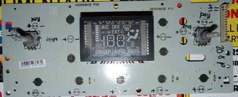
Here's how the project went:

First pic board shows the polarity.
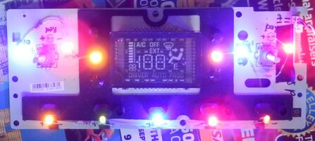
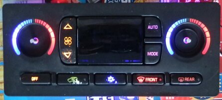
Second with the board lit up. I used 5 leds in series with a 50ohm resistor on the bottom row. For each side on the top I used 3 leds in series with a 330 ohm resistor. Note that the top two pins of the connector on the right side are backlight power - you should power up the light circuit before reassembling to be sure it works right.
Last pic is final result. Still needs to have the worn out symbols painted on.....
 

Attachments

  • TB auto HVAC 2.jpg
    TB auto HVAC 2.jpg
    161.8 KB · Views: 24
  • TB auto HVAC 1.jpg
    TB auto HVAC 1.jpg
    58.5 KB · Views: 32
  • TB auto HVAC 3.jpg
    TB auto HVAC 3.jpg
    44.2 KB · Views: 29
Last edited:
Mar 30, 2016
1,465
KSA
Here's how the project went:

First pic board shows the polarity.
Second with the board lit up. I used 5 leds in series with a 50ohm resistor on the bottom row. For each side on the top I used 3 leds in series with a 330 ohm resistor. Note that the top two pins of the connector on the right side are backlight power - you should power up the light circuit before reassembling to be sure it works right.
Last pic is final result. Still needs to have the worn out symbols painted on.....

Ohh. Colorful!!! 😂
 

xavierny25

Member
Mar 16, 2014
6,372
Staten Island, N.Y
Finished up the led swap on my replacement cluster since I really messed up the first one. 20190201_165303.jpg
(Don't mind the avg. econ mpg since this is a replacement and hasn't really collated any info yet. lol)
I went in and removed the blue from around the speedometer, oil, temp, battery and gas gauge. I left the gas and battery icons blue. Looks even better in person and its very different from what everyone else. I might have to go back in and clean the lens and some stains near the speedometer.
I'm scheduled to go in and have the mileage adjusted cause its about 70k off.
 
Last edited:

Capote

Supporting Donor
Member
Jul 14, 2014
24,227
Atlanta, GA
That's awesome man. how hard is it to swap to LEDs?
It's very easy, there's a tutorial in this thread IIRC, on both the method with individual LED replacements or the use of LED strips in their place.
 
  • Like
Reactions: xavierny25

Capote

Supporting Donor
Member
Jul 14, 2014
24,227
Atlanta, GA
Fantastic. I saw a display a while ago that was sweet, so I'm kindof thinking of copying that. black body, deep purple lights.

Guess I better start reading
I suggest go the LED strip route, no hot spots or areas lacking in illumination.
 
  • Like
Reactions: jpinoy
Jan 10, 2018
134
Michigan
Sounds good, ill go that route then. have you seen reviews or used any exterior LED strips? We can use them sparingly in Michigan, I wanted to have a faint glow in my hood scoop, but curious as to how they hold up against the elements
 

Capote

Supporting Donor
Member
Jul 14, 2014
24,227
Atlanta, GA
Sounds good, ill go that route then. have you seen reviews or used any exterior LED strips? We can use them sparingly in Michigan, I wanted to have a faint glow in my hood scoop, but curious as to how they hold up against the elements
I used the ones that they sell in Autozone, the brand is called "Alpena" (they're manufactured in Canada). I used their "MAX" series ones, which have 5053 diode LED's, which are very bright. I used these exact strips when I was running LED strips in my wheel wells, up until a few months ago. They lasted and ran whenever the truck was powered up without issues since 2012. Don't let the Autozone factor pry you away, they are superb! You can buy them on Amazon and Ebay for cheap.
 
  • Like
Reactions: xavierny25

richphotos

Member
Feb 26, 2016
298
St. Louis Park, MN
I've started something and hit a bump.

Doing quad brake mod with switchbacks in the reverse sockets. It's all together and works when testing the pins on the board but when I put the lights in the truck and turn them on, the Amber's stay lit
Quad brakes work like they should.

I am guessing I got the ck boards? Has the metal leads instead of wires.

Is there any way to get this working? I've seen it done but unfortunately all the pictures are gone with photobucket. Or is it the type of socket I used for the reverse? I got a 3157 socket off amazon.


*edit*

I think its because I am trying to use a CK bulb in a standard socket (the sockets I got from amazon are standard and not CK)

I have placed an order for standard switchbacks and will report back.
I am still open for discussion on if there could be another reason.

But the CK bulb in the standard socket is my guess.
 
Last edited:

Blckshdw

Original poster
Moderator
Nov 20, 2011
10,747
Tampa Bay Area, FL
Yeah mismatching the pin types could definitely cause that. When you tested your boards, were the + on the same side of the socket? If so, then those would be CK boards. If the + were both on the end of the socket, facing each other, then they are standard.
 

Mounce

Member
Mar 29, 2014
13,667
Tuscaloosa, AL
I had a recent set of switchbacks do that on my truck, well I didn't test pins but they were amber instead of white. Luck of the draw, I had installed both backwards. Flipped them around and they were white as should be.
 
  • Like
Reactions: Blckshdw

Forum Statistics

Threads
23,681
Posts
641,971
Members
19,138
Latest member
wentzben

Members Online

No members online now.