OK - still pretty new to LEDs. I want to fix my steering wheel lamps, and since I've gone red I figure I'll do red there as well. I'm looking at
these LEDs.
They re 2.0 volts, 30 milliamps cont forward current. The physical dimensions are: 5 mm diameter, 6.8 mm tall.
Questions:
When you calculate for resistors, do you use 12 volts, or do you think it better to use 13.2, 13.5, 14,...? I've usually found most cars about 13.2, but this is the newest one I've owned (and most advanced electronically). I figure better to go higher and likely the LED will live longer. Maybe a few Mcd less, but still quite visible.
With the calculator I used, inputting 13.2 volts, 2 v drop, and 30 mA, it shows me 390 ohm, 1/2 w resistor. Sound right?
For anyone who has done the swap, did any of you have issues with size of the lamps going in? I found another lamp that I liked but wasn't sure about the size, etc. The other one is 7.5 mm square, produces 5500 Mcd and 10 lumens. It's
here.
As always, any help appreciated.
Thanks,
Marc aka Camera Nut


 First time I've had to contact a seller about an issue while the item was under warranty and I'm pleased (surprised, really) with the lack of resistance.
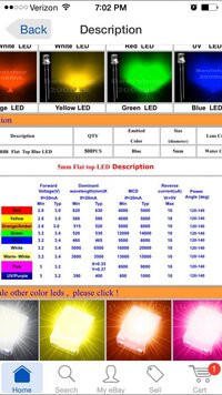


 Unless your mod bug is driving this project, and you end up with loose LEDs begging to be put elsewhere.


 Taco neck! Aarkon is rubbing off on you!


")