"Hoping... For Loping..."

mrrsm

Original poster
Lifetime VIP Donor
Supporting Donor
Member
Oct 22, 2015
7,639
Tampa Bay Area
It is a rare occasion when I can find a "Suitable Cheap Replacement' for my demand to use the Best Tools and Materials I can find for Engine Building. But in THIS case... Spending $80.00 for what amounts to being just being (2) 5/16" X 36" Mild Steel Rods to slide in through the two Hollow Ports under either side of the Camshaft Cover Retention Plate and keep the Disaster of Dropping (1) or MORE Roller-Lifters Down inside the LM-7 Engine Block from happening is STILL WAY more Money than I'd care to pay.

Using this Pair of Rods is a 'Necessary Evil' to ensure that ALL 16 Roller-Lifters will Remain Held UP Inside of the Lifter Trays after giving a few Quick Spins on the Nose of the Camshaft using a few Water Pump Bolts threaded in the nose of the camshaft to get enough Action on The Spin. The idea is that the Quick Rotational Velocity is supposed to Stuff all of the Roller Lifters high and tight up inside of their Black Plastic Retention Trays.

Ordinarily, that action alone on Newer or even Low Mileage Engines like my LM7 (73,000 Miles after 19 Years) would be enough to ensure that they all would remain held fast while performing the Camshaft R&R. But should any Mechanic suffer from the Fates and Gravity in that Moment... and if any of those Roller Lifters were to drop down into the bowels of the Engine... It would require a Total Re-Build of the Motor to get out the THAT Hell after experiencing such an unfortunate eventuality.

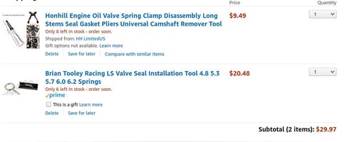
Still... In spite of my reticence to Drop $80.00 for this "Specialty Camshaft Roller Rocker Retention Tool Kit"... I think I've found a Respectable Substitute with the purchase of a (3) Pack of 5/16" X 36" Set of SMOOTH ALUMINUM RODS for only $19.18 with FREE S&H off of eBay. The only additional precautions I need to take is to Round and Smooth Over the two "Business Ends" of these Two Aluminum Rods. I've already seen too many YouTube Videos on LS Camshaft Swaps where the intrepid Mechanics wind up using 5/16" Wooden Dowels that can be observed snapping off here and there and leaving all sorts of debris inside of their engines... So I can only guess that my choice of using the more favorable and forgiving Rods made out of Aluminum will prove to be the Better Alternative.

But just in case there is any Metal to Metal resistance... I'll have them both lubed up with plenty of Perma-Tex "Ultra-Slick" Purple Jesus Engine Assembly Lube to ensure they can easily slide into each side of those two Hollow Ports under the Camshaft Cover ...directly underneath every single Roller Lifter and also reach all the way to the Back of the Engine Block.

Getting this task right means preventing any sudden drops of these (16) Slippery, Heavy Little Metal Cylinders... before I'm able to get the Old Camshaft OUT ... and the New TSP 212/218 112 LSA 550"/550" Camshaft correctly INstalled... as nicely as you please ...and then carefully withdraw those Aluminum Rods. I did a brief calculation of how many of these Tools Sets one eBay Vendor had sold... (27) Pairs X $80.00 ...just to figure out what the Profit Margin was on (54) 5/16" X 36" Mild Steel Rods. This came to be a figure of $2,160.00 ... So No WONDER the "S&H" on those (27) Sales were FREE!

I'm not certain how much these Aluminum Rods can be Bent to sort of Guide them inside of the Engine on a 'curve'. So the proximity of the Front of the Engine Block to the Radiator and Condenser Coil may become a critical factor to consider. However, since I have the Third Aluminum Rod to Experiment with... I'll look things over ahead of time and use IT to see whether on not it becomes absolutely necessary to Remove the Radiator Core AND move or adjust the Condenser upwards to clear the straighter path if needed to get both Rods inserted properly and NOT get them jammed up inside of the Motor. See the Attached Images for comparisons among these "Metal Rods":

LSLIFTERETAINERS.jpgPOWERHOUSELIFTEROOL1.jpgPOWERHOUSELIFTEROOL.jpgPOWERHOUSELIFTEROOL2.jpg
 

Reprise

Lifetime VIP Donor
Supporting Donor
Member
Jul 22, 2015
2,724
While I certainly *hope* you don't lose a lifter inside the block... chances are, it would drop into the windage tray. So you'd have to take off the pan & tray -- which is a major pain in the tuchus, especially on a 4WD -- but I don't think you'd be stuck tearing down / rebuilding the bottom end.

As you may recall, I plan on pulling / replacing the heads, and while I'm in there, replacing the lifters when I do my cam swap. So I won't need to worry about dropping one. But I'll keep my fingers crossed for you, of course.

Interesting choice of grind for your cam. That looks like the very same cam I was going to go with, originally, before I decided to go with a Comp w/ different specs. It should do better w/ your 4.8, than it would for me, in my 6.0

That 112 LSA should, indeed, supply a pretty noticeable lope. At .550 lift, you're right at the max for the blue springs - but you should be OK, I think, unless you're planning to 'get on it' all the time. I'm ordering up a set of the 'blues' for mine as well, although I won't be pushing more than .525 on either end.

The cam I'm getting for my LQ4 has a 115 (+4) LSA, and I was told that it should idle pretty smoothly (and also that the choppier the idle a cam has, the less power it's going to have down low). '116' LSA would be closest to stock, the way I understand it.

Looking forward to your report on how it all runs, post-install.
 

mrrsm

Original poster
Lifetime VIP Donor
Supporting Donor
Member
Oct 22, 2015
7,639
Tampa Bay Area
As with everything I write... sometimes I try to describe and place the 'dramatis personae' (those Mean Old Engine Components and R&R Procedures in this case) in the roles of "The Enemy" to stress the Downside that Taking Things Too Lightly...Can make Things go Sideways in an unexpected manner. For most of the Folks who come to GMTN... getting this Deep in the Weeds of their Engines will be a 'Scary Thing'. So whenever I'm explaining things that demand Excellence and Precision using Mechanical Skill... on occasion, I like to use "Dramatic Effects" and occasionally a bit of Hyperbole to make sure that when giving advice to any who'll want to try doing this Cam Swap for the first time... that being ...Sh*t Scared... is a Good Thing. Pulling the Windage Tray-Knock Sensors will be the LEAST of the issues they'd have to deal with if any of the Roller-Rockers were to Drop. By the time they get the Intake Manifold and those Engine Head(s?) removed ... Stripping down the upper Engine Block might as well be a Full Engine Re-Build... because to the Novice Engine Builder... THAT is exactly what it will feel like.

My choice of The Stage 2 "Low Lift" CAM Kit from TSP for my LM7 5.3L V8 is almost entirely based upon How Good that Motor Sounds at a Choppy Idle... Rather than as matter of Power for the sake of Practicality. I would hate to go though all of this time, effort and expense only to discover that my Full Size Truck... while having More Punch right Off The Chocks... also Idles Without ANY Noticeable LOPE ...which is The Main Title of this Movie "Hoping for Loping". I will not be towing anything weighing nearly Two Tons up and down 15 and 20 Degree Road Grades nor Rocking the Red Lights on the Main Drag Strip Downtown seeking to take the car next to me off of the Line when those lights turn GREEN. I'm just a Selfish Old Man who just wants to sit on very comfortable Leather Seats, Turn the Ignition Key and watch and feel my Truck Rumble to Life in a way that Lopes and Sounds like the Mean Holy Grail of Horsepower is hiding under the Hood... right in front of me; else all of this work I'm about to do will be for naught if I cannot sense all of those things while just tooling around on the local roads. :>)

I've been reading a bit recently that one of the Options for a 4L60E Transmission and Torque Converter that can bump the RPM Stall Band a LITTLE bit higher than the Bone Stock setup in my 2000 Chevrolet Silverado... is to use the 4L60E & TC out of...of all things... A TRAILBLAZER. Now I haven't quite figured out why that would be the case... but since I have the Old Trans & TC out of my 2002 Trailblazer sitting somewhere out in my Garage... If I come to find out that in the 1,500 to 2,500 RPM Band, the Truck is so Choppy that it either wants to Stall at Red Lights and/or takes too much time to stagger up to speed from Low RPM (beginning without having any Tune applied to level things off) then I might consider Re-Building that Old Trailblazer Transmission and Flush out the Torque Converter for a Fresh installation into the Silverado... but, only if necessary. So I'll 'Cross that Rubicon' if and when I get there.

By the way... your choice of the 115 Lobe Separation Angle and .525"/.525" Lift does make sense for everything you need with your vehicle. You wouldn't necessarily have to put in a 1:1.7 Roller Rocker Trunnion Upgrade Kit and you can still use the GM OEM Stock 7.4" Push Rods, too, as long as your Comp-Cam Bump Stick Base Circle remains the same as the one in your LQ4. If you manage to get going on your Build and Start a Fresh Thread soon... Please post up as many Before and After Images of your work as you'd care to... I'm certain that everyone will be very curious about your CompCam Performance Camshaft Upgrade Undertaking here as well.
 

littleblazer

Member
Jul 6, 2014
9,265
While I certainly *hope* you don't lose a lifter inside the block... chances are, it would drop into the windage tray. So you'd have to take off the pan & tray -- which is a major pain in the tuchus, especially on a 4WD -- but I don't think you'd be stuck tearing down / rebuilding the bottom end.

As you may recall, I plan on pulling / replacing the heads, and while I'm in there, replacing the lifters when I do my cam swap. So I won't need to worry about dropping one. But I'll keep my fingers crossed for you, of course.

Interesting choice of grind for your cam. That looks like the very same cam I was going to go with, originally, before I decided to go with a Comp w/ different specs. It should do better w/ your 4.8, than it would for me, in my 6.0

That 112 LSA should, indeed, supply a pretty noticeable lope. At .550 lift, you're right at the max for the blue springs - but you should be OK, I think, unless you're planning to 'get on it' all the time. I'm ordering up a set of the 'blues' for mine as well, although I won't be pushing more than .525 on either end.

The cam I'm getting for my LQ4 has a 115 (+4) LSA, and I was told that it should idle pretty smoothly (and also that the choppier the idle a cam has, the less power it's going to have down low). '116' LSA would be closest to stock, the way I understand it.

Looking forward to your report on how it all runs, post-install.
It's funny you mention LSA... usually the tighter (smaller) the LSA is the more peaky and quicker torque comes in and the wider the LSA is the broader your power curve is iirc. However you tend to lose bottom end as you go up in duration... that's always true except... when you match everything. If you optimize port velocity your VE goes way up and strange things happen.

When I build the 400 for the vette I'm doing a single pattern on a reasonably tight LSA with duration in the 230-238 range and around 560 lift. It'll have power low because the cam is pretty tame but carry it all the way up because of the short runners on the intake.
 

mrrsm

Original poster
Lifetime VIP Donor
Supporting Donor
Member
Oct 22, 2015
7,639
Tampa Bay Area
All night long... I’ve been mulling over my decision to avoid getting the Design Specific Tool for retaining LS Engine Roller Rockers up inside of their Plastic Guide-Trays. So after also double checking prices for an American Made LS Valve Spring Compression Tool Kit that rivals the one from ProForm ...and at a much lower price… I finally decided to just get them both and be done with it.

The more I thought about those Aluminum Rods sliding back and forth under the Roller Cylinder bottoms of the (16) Roller Lifters… the more concerned I became about the possibility of shearing or scraping off small pieces of Aluminum from the sides of those Rods and having all of that Junk getting jammed up in between the Roller-Lifter Cylinder Ports those things ride up and down inside of and maybe getting squashed in between and against the outer ODs of the Roller-Lifters.

So at least now… I can check off (2) more items from my Pre-Camshaft-Valve-Spring Swap Job “To-Do” List. Since my Son’s 2003 Chevrolet Silverado sports the 4.8L V8 Engine… I may want to do this same upgrade job to his Truck in the future whenever we venture up to visit the family in North Florida. Having the tools and the practice I expect to experience very soon while working on the Y2K Silverado certainly won’t hurt a bit to ensure a likewise Better Performance Upgrade outcome on his ‘03 Silverado. These two separate Tool Kits were both available on eBay. Please take note that with close to 800 eBay Sales for the LS Valve Spring Compressor Tool Kit… it tells me the word got out that this Kit will perform every bit as good as the ProForm version does. We’ll soon see…:

LSVALVESPRINGCOMPRESSORTOOLRECEIPT.jpgLSROLLERLIFTERETAININGTOOL5.jpgLSROLLERLIFTERETAININGTOOL4.jpgLSROLLERLIFTERETAININGTOOL2.jpgLSROLLERLIFTERETAININGTOOL1.jpgLSROLLERLIFTERETENTIONTOOLRECEIPT.jpgLSROLLERLIFTERETAININGTOOLIMAGE.jpg
 
Last edited:

mrrsm

Original poster
Lifetime VIP Donor
Supporting Donor
Member
Oct 22, 2015
7,639
Tampa Bay Area
Just to clarify the notion of WHERE inside of the Engine Block the Roller-Lifters would wind up IF “...The Lifters Accidentally fell down inside of the LS Engine Block…!”… This Mechanic shows us his LQ4 being fitted with the Roller Lifters originally meant to be inside of an LM7 Engine (Non-DOD Non-AFM). First, he Lubes all of the Lifters with Motor Oil and then he inserts the ‘Slippery Devils' in pairs per cylinder (Four Pairs per Bank) into Brand New (...think Snug and Unworn Here) GM OEM Black Plastic Lifter Alignment-Holding Trays.

His follow-on actions illustrate just how ‘Deep inside of the Engine” these lifters would REALLY fall if after the Old Camshaft was slid out of the Engine Block at the time such a catastrophe occurred. The Insurance against this problem of course, is using the Long “T” Handle Twin Lifter Restraining Rods inserted through the Block from Front to Back. Those Rods keep all of the Lifters elevated well above the Camshaft Bore Holes during the Swap, making perfect sense NOT to rely upon how well those Plastic Trays MIGHT work, beyond simply keeping each Lifter ‘Roller’ aligned evenly with the smooth elliptical 'rolling' surfaces of the (16) Lobes on the Cam.

None of the actions taken by the Video Original Poster (VOP) as he ‘finger-lubes’ the Roller-Lifter Passageways are possible to do when the Engine Heads are installed on the Block. But... If this Dude’s Camshaft had NOT already been ‘glided’ through the mid-center of the Engine Block with the Cam Journals right where they are supposed to be, once freed from the ‘hold’ promised by those “NEW” Plastic Trays, if any one of them fell free from its Tray and tumbled down even deeper inside of the Engine, it would be well nigh impossible to get at them, short of pulling that Motor apart to access its “innards”.


mrrsm

Original poster
Lifetime VIP Donor
Supporting Donor
Member
Oct 22, 2015
7,639
Tampa Bay Area
Because I forgot to actually line up and takle any "Before and After" Comparison Shots of the Pre and Post Trunnion Bearing Upgrades... I'd already disassembled all (16) Rockers down to the the "Empty cages". So I decided to just hunt down a Brand New GM OEM Roller Rocker Arm on eBAy to act as a Stand-In when making these Follow Up Images and for a modest $15.00... I found a 'BNIB" (Brand New In the Bag) Corvette. Roller-Rocker Arm; Still inside of the unopened GM OEM Bag. What could be better, Right?

However... as I got to the point of actually positioning The New Corvette RR Arms vs. The Post-Trunnion Roller Rockers along side one another... I began to notice some subtle and some NOT-SO-SUBTLE Differences while taking a dozen or so pics of these two items for comparison. The Corvette RR Arms seems to have a Thicker Trunnion Buttress making it look more massive at its core. The actual Trunnion Axles appear to be the same... but when I take it apart... I'll Mike their Outside Diameters and see if those oddly shaped inner axles appear equal to the ones that came out of the Older Set of Arms. The same observations have to be made between the Old RR Arms Bearing Cases, Races and actual Tiny Bearing Dimensions to see if perhaps THIS Corvette RR Arm is some kind of a GM Upgrade to solve the "Bearing Case Failure"..

The last thing worth mentioning is that the GM OEM Parts Bag was marked as: ARM EXH. which kind of puzzles me and has me wondering if the Roller Rockers in some or all of the LS Engines actually have differences between where they need to be mounted for either the Intake or the Exhaust Valves in the Engine Head. This seems important enough to do some More Research on and posting the attached images will allow everyone to judge for themselves.

Would it cause a problem to mount this Roller Rocker (Post Trunnion Upgrade) on the same Rack of Rockers due to these idiosyncrasies? I don't know... The Roller Rocker Lift ratio still looks like its at 1:7 to 1 to me... so my thinking is that these OTHER Built Up Differences should not make THAT much of a difference. The only other thing necessary to find out now is "How does the Corvette Roller Rocker Arm SIT in the Mounting Bracket? Is it level with all the others in Height?"...etc. So... I'll be poking around to see what I can find out. In the mean time... The Caveat should be... "All LS Engine Roller Rockers are NOT the Same..." until I can prove otherwise:

CORVETTEROLLEROCKER2.jpegCORVETTEROLLEROCKER3.jpegCORVETTEROLLEROCKER4.jpegCORVETTEROLLEROCKER5.jpegCORVETTEROLLEROCKER7.jpegCORVETTEROLLEROCKER8.jpegCORVETTEROLLEROCKER9.jpegCORVETTEROLLEROCKER12.jpegCORVETTEROLLEROCKER14.jpegCORVETTEROLLEROCKER15.jpegCORVETTEROLLEROCKER16.jpegCORVETTEROLLEROCKER11.jpeg
 

mrrsm

Original poster
Lifetime VIP Donor
Supporting Donor
Member
Oct 22, 2015
7,639
Tampa Bay Area
Okay… While this idea would not occur from the average person's experiences… in the in-between time of waiting for the bulk of the “Nose to Tail” Y2K Performance Exhaust Upgrade Hardware to arrive, I had a strange reminiscence that related directly to whether or not the DNA Company that sold me my Headers and CAT-Back Exhaust would have everything in the Kit made out of One Thing: T-304 Stainless Steel. It gets a little bit weird for the next few paragraphs...so if you are the least bit squeamish... just drop down to the bottom of this post and look at the attached images:

I realized from quite a few professional experiences during Murder Investigations. that when you are in the presence of a LOT of Human Blood often encountered at Homicide Crime Scenes… the atmosphere in those unfortunate places fills up the Air with the Powerful, Aromatic Smell of RUST.

This happens due to the fact that in the presence of an abundance of Blood being exposed to Air; even Postmortem... the roughly 22% of Oxygen that is always available at Sea Level in the Atmosphere will continuously combine with the FE203 (Ferric or Ferrous Oxide) present in all of that bloody mess; by literally latching onto all of those exposed Hemoglobin Molecules in very Red Blood Cell... changing each one making contact with O2 Molecules into a Brownish material that becomes Darker and more evidently “Rusty” the longer the liquid remains exposed ...right up until it finally coagulates and completely dries.

Anyway... All That Said… I realized from those memories that if and when those DNA Exhaust Pipes and Muffler arrived… I figured that if I was able to detect the “Smell of RUST” in the Air, THIS would clue me in that since the Advertisement and Sales data I’d originally read Did Not actually SPECIFY that the COMPLETE System WOULD be made of S/S, then the presence of a Strong Rusty Odor, that would indicate that in general, the majority of the CAT-Back Piping would probably be made of none other than just Plain Old Mild Steel Tubing.

HOWEVER… I’m VERY happy to advise that right along with the arrival of the Texas Speed & Performance Stage 2 Camshaft Kit, the DNA CAT-Back Exhaust Carton ALSO arrived as well… and 1-2 Months Early! So, to test this idea I’d previously been curious about, I tore into that DNA Carton like a Kid on a Christmas Morning and while inhaling from the interior of that big box, could detect...Nothing. Just the smell of Cardboard and Plastic Bubble Wrap covering the contents and NOTHING else suspiciously smelling like any RUST was present.

The SECOND good indicator that 'All Might Be Well' was also the lack of any “3 & 1 Oily” Smells, This fact was equally confidence building and I went about getting everything un-boxed and laid out for a quick inspection. No Damages or Dents were found to anything; other than to the cardboard packaging itself. So far... So good… No “Oily Smell” always means one thing: ALL of the Metal Components were Made of T-304 Stainless Steel... which “Never Needs Oiling to Prevent Rust In Transport...”.

I laid all the sub-parts laying around in order to take the requisite “Show & Tell” photography for GMTN and then I made the observations of just how much larger a 3” Exhaust Pipe System truly is than one might think. The attached images will illustrate this in plain views that strongly suggests of Very Little Back Pressure restricting the Post –CAT Treated Exhaust Stream once this system is properly aligned and fitted into place; either with New Rubber Hanger Supports, many Wide S/S Buttress Clamps and some Common Nuts,Bolts and Washers to fasten the front end of the CAT-back Pipe to the back end of the Catalytic Converter. Just as with the Pipe Tubing, the DNA Muffler was likewise confirmed as being completely manufactured of Stainless Steel.

The images I took of THAT 'Large Mouthed Bass' looking Thing are more meant to assist ME with getting some Help here in figuring out “Which of the Two Equal Size Short Pipes on the Muffler is menat to FACE FRONT and which of them is The Pipe End that Trails and Exits out the rear of the Y2K Silverado?” When I looked down inside of Both Ends… One seems to show a Shiny, Stainless Steel Plate... very close to the Short Pipe of the Muffler Body. The other end is set much deeper inside and you can see in the attached images various Baffling and Screen Corrugations inside on the perimeter of the “innards”. So the only remaining, Burning Question is... "Which End is the Right End for the Front Vs. the Rear Positions?"

All of the these Sellers of similar Exhaust Systems share the very same Liability Mantra':

Professional Installation is Recommended ...No Installation Instructions are Included..."

I suspect this has come about as an unwritten, but Tacit Agreement that if these Exhaust Systems are being sold to “The Great Unwashed” Public… sending them to “The Pros” after the Sale will shunt any Lobbying Efforts on their part to make more laws to prevent people from being able to work UNDER their vehicles as well as trying to Stop People from Fixing their own vehicles from the TOP Down. I won’t be installing this Exhaust System until I get some reliable and definitive help on this matter because from a 'Bird's Eye View"... THIS S/S Muffler looks the same from Both ends.

The very eventful Un-Boxing of the Texas Speed and Performance Camshaft Kit did NOT go very well as they FUBARed my Order and sent me a Stage (1) Low Lift 208/214 112 LSA 550”/550” Cam Kit ...so they obviously got the Specs I Specified on my Order WRONG! I HATE having to Hassle with sending Sh*t Back... So I'll be on the Phone in the AM to TSP and try to get this problem sorted FAST. The follow up on this will be a subject for another day and nothing further needs any elaboration beyond what the attached images clearly show.

Just know that purchasing the necessary COMPLETE INSTALLATION Kit, which includes the New Timing Cover and Water Pumps Gaskets along with the Front Timing Cover Crankshaft Seal and “Jesus Crank Bolt” will save you a lot of time and hassle of having to run all of those things down prior to when it comes time for the Final Post-Cam Swap Re-Assembly.

One Last Honorable Mention goes to the Rolled, Polished S/S 3” to 4” Tail Pipe Extension “Blingy-Thingy” looks as much from the size of it like a Once Fired 155 MM Howitzer Artillery Round Casing as it looks like being a part of any Exhaust System. THAT Damned Thing is NEVER going to slow down ANY of The Exhaust Stream AND it Looks Cool as Hell! . LOL :>)

The presence of all of this hardware meant that I had quite a few images I took to Post Up… So they have to be delivered here by breaking them up as attachments to an additional follow-on posts:

DNACATBACKEXHAUST1.jpgDNACATBACKEXHAUST3.jpgDNACATBACKEXHAUST5.jpgDNACATBACKEXHAUST6.jpgDNACATBACKEXHAUST7.jpgDNACATBACKEXHAUST8.jpgDNACATBACKEXHAUST9.jpgDNACATBACKEXHAUST10.jpgDNACATBACKEXHAUST11.jpgDNACATBACKEXHAUST12.jpgDNACATBACKEXHAUST14.jpgDNACATBACKEXHAUST15.jpgDNACATBACKEXHAUST16.jpgDNACATBACKEXHAUST18.jpgDNACATBACKEXHAUST19.jpgDNACATBACKEXHAUST2.jpgDNACATBACKEXHAUST17.jpgDNACATBACKEXHAUST4.jpg
 
Last edited:

mrrsm

Original poster
Lifetime VIP Donor
Supporting Donor
Member
Oct 22, 2015
7,639
Tampa Bay Area
....and here are the rest of what I mentioned for related images in Post #48:

DNACATBACKEXHAUST24.jpgDNACATBACKEXHAUST26.jpgDNACATBACKEXHAUST27.jpgTSPCAMKIT03.jpgTSPCAMKIT04.jpgTSPCAMKIT07.jpgTSPCAMKIT08.jpgTSPCAMKIT09.jpgDNACATBACKEXHAUST21.jpgDNACATBACKEXHAUST25.jpgTSPCAMKIT01.jpgTSPCAMKIT02.jpgTSPCAMKIT06.jpgTSPCAMKIT07.jpg
 

mrrsm

Original poster
Lifetime VIP Donor
Supporting Donor
Member
Oct 22, 2015
7,639
Tampa Bay Area
A VERY Necessary Correction and Apology to Texas Speed and Performance is in 'Order' regarding the Mix-Up in my NOT receiving the CORRECT TSP Stage 2 Low Lift 212/218 112 LSA .550"/.550" Camshaft Kit...

I'm neither a Catholic nor a Religious person... per se... But I offer a very penitent:


Mea Culpa... Mea Culpa... Mea Culpa...

... here, for this is a FUBAR ....entirely one of my OWN making; ... hopefully a temporary condition I rarely if ever fall into called.. HMHUMA. I made the mistake while adding in the Final Order Specifications for the Stage 2 Camshaft Kit while on the Texas Speed and Performance "Check Out lane" Page by ... refreshing the Web Page... and this set the DEFAULT CHOICE for my Order right back to the Stage 1 Kit Parameters.

Thus, I screwed up and mistakenly Ordered the Wrong Camshaft Kit. I tried to call TSP, however they are closed on Weekends... so I'll try to reach them again on Monday, June 10th, 2019 and seek to obtain an RMA # ASAP and get this Kit FedEx'ed right back to them and then just start all over again. Please keep that "Page Refresh" issue in mind as a potential stopping issue if you make any purchases... and remember to TRIPLE Check the Cam Kit Stats before Pulling the Trigger to BUY:


I may start with the S/S 3"Muffler- Exhaust System because, for the sake of the Before -N-After Baseline... simply because it makes sense to conduct these Upgrade Installs in Stages that Compliment the Gradual Improvement in the Sound of the Exhaust and the Performance of the Engine and to record these events in their Proper Order:

(1) Record the Truck Exhaust Idling in its present 'Stock as a Clock" Condition..
(2) Record the Truck Exhaust idling AFTER the DNA S/S CAT-Back System is Installed.
(3) Record the Truck Exhaust Idling AFTER The DNA S/S Headers are Installed.
(4) Record the Truck Exhaust Idling AFTER the TSP Camshaft Kit is Installed and During its Initial Start-Up.


The Attached images show that the "Made in The USA" Valve Spring Compression Tool Kit arrived and now THAT is one less thing for me to worry about as I continue making progress; albeit One step Forwards and Two Steps BACK of late... due to My Own Fault. But this will change as soon as I get to work on performing these much anticipated R&Rs.

VALVESPRINGTOOLKIT1.jpgVALVESPRINGTOOLKIT2.jpgVALVESPRINGTOOLKIT4.jpgVALVESPRINGTOOLKIT5.jpgVALVESPRINGTOOLKIT3.jpgVALVESPRINGTOOLKIT6.jpg
 

mrrsm

Original poster
Lifetime VIP Donor
Supporting Donor
Member
Oct 22, 2015
7,639
Tampa Bay Area
Okay... So I've some very Good News relating to contacting the Customer Service and Sales Department of Texas Speed and Performance on Monday, June 10th, 2019. I spoke briefly with "The Dude" abiding...and explained my FUBAR on my original Order. I advised him that I understood there would be a 20% Re-Stocking Fee and that I would have to cover the FedEx S&H for the Returning Camshaft and Installation Kit.

He was great about the situation by advising me, "How 'bout we just do it as a Straight Exchange and there will be no requirement for the Re-Stocking Fee...?" I agreed of course and after DOUBLE CHECKING with him about getting THIS Camshaft & Installation Kit during this exchange, he provided me with an RMA#. The interesting part about this conversation was that he asked me no further questions and did not challenge me about whether or not anything inside of the Wrong Kit I had ordered had either been Opened, Installed, Uninstalled...or Damaged. So THAT was a Very Kool Kustomer Assistance event... Me likely! Again... THIS stuff is what is coming next from TSP:

TSP Stage (2) Low Lift 212/218 112 LSA .550"/.550" Camshaft Kit (included LS6 Valve Springs)
Accessory Installation Package


Yesterday morning, the Powerhouse LS Camshaft Roller Lifter Retention Tool Kit arrived. I un-boxed and photographed everything and note that this Specialty Tool is made of "Blued" High Grade Steel... with the two "T" Handles being very nicely Machined to screw inside of their outer ends with just the right amount of snugness. I'm impressed with everything about them and considering how much time and effort the Seller used just to get these Tool Segments, 'Wrapped and Packed" into its protective Cardboard Tube... You can tell right away... These People at Powerhouse aren't messing around.

The more I think about why they made this device the way they did...the more I understand that one has to use great care when sliding these rods through the front face of the Engine Block and NOT allowing the Roller Lifters to all drop down onto its OD and get STUCK. These "T" handles were not Machined as Well and as Strong as they were... Just for SHOW. It may require some amount of real, physical 'coaxing' to get these Rods to slide in and Under the Lifters... and then slide right back out of the Engine Block as soon as the New TSP Camshaft is installed... without jamming up inside or damaging the Roller Ends of all (16) Lifters.

For the benefit of our GMTN Members, I took some Overall Measurements of these Tool Segments to give anyone intent upon doing this job some idea of Just How Much FREE SPACE AND ROOM will be required in between the radiator and the smooth face at the front of the Engine, once the Water Pump, Front Timing Cover and the Large Camshaft Sprocket have been removed, of course.

Depending upon whether you have a Full Sized Truck or the smaller GM and GMC versions of the SUVs... the amount of free space will naturally vary ...and measuring in between those locations may save you a LOT of extra "collateral R&R work". Personally, having seen how RIGID these Specialty Rods really are... rather than risk Bending and Breaking them during this procedure, I'd opt to remove the Radiator first... and if really necessary, R&R the A/C Condenser Coil as well and be done with guessing about it. Here are the Tool measurements and the images of this Kit:

Powerhouse LS Camshaft Roller Lifter Retention Tool(s)
Length: 20.00" w/o the "T" Handles Threaded Inside of the Rods
Length 21.75" WITH the "T" Handles Threaded Inside of the Rods
Width: 0.3015" (7.67mm) using an Inside/Outside Micrometer (Accurate to .0005")


POWERHOUSERODS3.jpgPOWERHOUSERODS4.jpgPOWERHOUSERODS5.jpgPOWERHOUSERODS7.jpgPOWERHOUSERODS8.jpgPOWERHOUSERODS9.jpgPOWERHOUSERODS10.jpgPOWERHOUSERODS12.jpgPOWERHOUSERODS14.jpgPOWERHOUSERODS15.jpgPOWERHOUSERODS16.jpgPOWERHOUSERODS18.jpgPOWERHOUSERODS1.jpgPOWERHOUSERODS6.jpgPOWERHOUSERODS2.jpgPOWERHOUSERODS17.jpg
 

mrrsm

Original poster
Lifetime VIP Donor
Supporting Donor
Member
Oct 22, 2015
7,639
Tampa Bay Area
As these Projects progress and take on lives of their own... when the 'Hands-On R&R's' draw nigh... there always seems to be those "Additional Ancillary Components" that have to be considered as being able to "Put The Brakes On Progress..." if they get overlooked and are NOT ordered right along with all of the Major Parts and Pieces necessary to have on hand. While far from being a complete list of these same said PITA things to get... Today's acquisitions are from RockAuto and are as Follows:

(16) Felpro Intake and Exhaust Valve Seals Kit Complete (All Black)
(8) Mahle (Victor Rienz) Intake Valve Seals (Blue)
(8) Mahle (Victor Rienz) Exhaust Valve Seals (Brown)
(48) Sealed Power Stock Valve Stem (Single Groove) Half-Shell Keepers
(4) Walker Rubber Exhaust Hanger Insulators


These Valve Guide Seals wre BOTH either available as Close-Out Sales... or were just Too Damned inexpensive to pass up. In the meanwhile... I'm still on the Lookout for some Brand New Beehive Valve Spring Keepers as well. The attached Proof Of Purchase Screen Prints from RockAuto have some additional Part #s and other useful, related Information:

ROCKAUTOANCILLARIES1.jpgANCILLARYPARTSANDPIECES1.jpg
 

mrrsm

Original poster
Lifetime VIP Donor
Supporting Donor
Member
Oct 22, 2015
7,639
Tampa Bay Area
While I’ve been waiting for the “Correct Swap” Texas Speed and Performance Camshaft Kit to arrive… I’ve been busy with acquisition of an Actron Digital Color Probe Camera. After practicing and experimenting around with it quite a lot, I've decided that using it really will speed up the time it takes to determine ‘Without a Shadow of any Doubt’ that prior to applying the Valve Spring Compression Tool onto all (16) Valves in the LM7 Engine Heads… I’ll be completely certain that each of the TDC-Of-Pistons-Per-Cylinder are truly Positioned Right at Top Dead Center. This Tool will eliminate the slightest possibility of my accidentally “Dropping Any Valves' down inside of the Cylinders once the Old GM OEM Valve Locks and Keepers have been loosened and removed; releasing the Spring Retention Holding onto all (16) of the Cylinder Head Valves:

ACTONBORECAMERA9.jpeg

But while viewing this event on the 2.5" Screen of this Color Video Camera demonstrates more than its fair share of useful features... I still want to take this Idea One Step Further as far as Preventing the 9 MM Camera Lens from Poking Too Far Down Inside of the Combustion Chambers. I suspect that it might accidentally get Shattered if the Camera Lens were to get wedged in between the Rising Piston and the Upper Combustion Chamber, squashing it with ease:

ACTONVIDEOCAMERALENS.jpg

To accomplish this, I figured the Best Method is as follows:

(1) Obtain a Brand New Set of ACDelco R44LTSM Spark Plugs.

ACDELCOLM7SPARKPLUG1.jpgACDELCOLM7SPARKPLUG2.jpg

(2) Then single out One of the Used Spark Plugs to be Drilled Out Clean Through down to a snug Inside Diameter approximating the 9 MM OD of the Video Camera Lens. Then determine just how far inside of that Spark Plug the Lens can go to be able to see the Piston Clearly as it attains TDC.
ACDELCOLM7SPARKPLUG1A.jpgACDELCOLM7SPARKPLUG2A.jpg

(3) Wrap enough Electrician’s Tape around the Camera Flex Cable right at the Specific Camera Lens Depth to act as a reliable "STOPPER":

ACTONVIDEOCAMERALENS2.jpg

(4) Then Lightly Screw In the Drilled-Out Spark Plug (8) Consecutive Times for these TDC Video Confirmations and Use the Valve Spring Compression Tool to R&R The Old GM OEM Valve Springs for the New LS6 Beehive Valve Springs with New CompCam 7 Degree Retainers & Locks.

GMLS6BEEHIVESPRINGSKIT.jpg

I cannot think of a Better or Safer Plan for performing this oft' ‘Nerve-Wracking’ Task. :>)

More to Follow Shortly on additional arrivals of the "Supporting Cast of Characters"...
 

mrrsm

Original poster
Lifetime VIP Donor
Supporting Donor
Member
Oct 22, 2015
7,639
Tampa Bay Area
As mentioned… I had to pick up just a few more “Specialty Tools” that are strictly meant to help R&R those Damned PITA Valve Stem Seals that can either:

(1) Scratch and Damage the Smooth, Hardened Surfaces of Each Valve Stem during the Seal Removal-Replace events ...using the Wrong Tools.

(2) Damage the Delicate Spring-Tension Viton Inner Seal constructs during the Installation of the New Valve Stem Seals ...using the Wrong Tools.

BTRVALVESTEMTOOLKIT.jpg
HORNHILLVALVESTEMTOOL.jpg

For the Modest Cost and the HUGE Benefits of using these One Off Tools… It’s just not worth the time and effort to go Rummaging around inside of your Dirty Tool Boxes looking for and finding the Wrong Tools to take these necessary R&R Steps when trying to do these kinds of Jobs...Right.

For Example… Watch BTR’s (Brian Tooley Racing) Big Boss Man Himself in this Video (in the latter part) showing how the easily his "NEW" BTR - LS Valve Stem Seal Tool Kit makes this Valve Stem Seal Installation go PERFECTLY SMOOTH... (16) Times in a Row... and REMEMBER his Wise Advice... "HIDE THE HAMMER FROM YOURSELF..." :


The Three Quality Main Players for this LS6 Beehive Valve Spring Swap necessary to handle the .550"/.550" Lift are below. The BH Springs will be coming from Texas Speed and Performance... The Keepers and Locks ... from CompCam. I'm also suggesting here that you probably COULD use the "Stock-As-Clock" Keepers and Locks... But.. Why Look For Any Trouble with ALL the Bread You'll already be investing into Beefing Up Your LS Motor's Performance?

GMLS6BEEHIVESPRINGSET.jpgCOMPCAMKEEPERS1.jpgCOMPCAMKEEPERLOCKS.jpg
 

Attachments

  • VALVESTEMRANDRTOOLS.jpg
    VALVESTEMRANDRTOOLS.jpg
    31.4 KB · Views: 1

mrrsm

Original poster
Lifetime VIP Donor
Supporting Donor
Member
Oct 22, 2015
7,639
Tampa Bay Area
Okay... A few more things have arrived; some of which of necessity, I had to order as additional 'problem solvers' for things that WILL crop up incidentally during this Camshaft-Valve-Train Hardware Swap:

'Big Problems that develop during Mechanical Repairs... often have Small Beginnings...'

It is not possible to safely Re-Install the LS Harmonic Balancer-Serpentine Pulley without correctly using this Simple Tool Kit. Thankfully... the Brand New Crankshaft HB Bolt is NOT long enough to even get the Pulley slightly aligned and started back onto the Nose of the Crankshaft. But some people have tried to use the Old TTY Bolt to draw the HB Pulley inwards... and after only getting that Bolt wound inside the nose of the Crank... by a few shallow Thread Lines, they ended up tightening down the Old TTY Bolt and yanking those Threads RTF Out of the Nose of the Crankshaft.

I cannot recommend using High Powered Impact Tools for this Re-Installation Job for the very same reasons. And... It will also become an exercise in futility to Try to Beat the HB Pulley onto the Crankshaft with a Hammer... in the hope of accessing more thread lines for the Old TTY Bolt, as this can also Damage the Crankshaft's internal "Tune" and ruin the Harmonic Balancer's Elasto-meric Adhesive in between its two Heavy Segments, defeating its designed purpose as well.

This Basic Tool Kit is composed of a decent length of Threaded Rod made of Hardened Steel that mates and threads inside of an equally Hardened Steel Nut. The whole apparatus works because the tightening force gets distributed over a WIDE AREA by using the Two Large Galvanized Washers to spread out the pressure in between them by aligning the Force applied from the Nut/Washer Combo... exactly Dead Center through the Crankshaft. This circumferential equal Pull on the Harmonic Balancer avoids getting more pressure on one side or the other as it withdraws the HB outwards.

'As AREA INCREASES... pressure decreases..."

Hopefully, the User will have prepped this Tool by placing a Small Dollop of either Redline High Pressure Grease or Molybdenum Di-Sulfide Grease in between those Wide Washers to even further reduce any friction. It is also necessary to generously spread that same Grease along the full thread-lines of the Long Bolt. With all of this careful preparation done, then the HB Pulley can gradually be drawn inwards over the nose of the Crankshaft without doing damage to any of 'The Players" in between.

These procedures may all seem all too simple enough to deserve so much focus on these banal details and "Probably not worth worrying about..." for most Mechanics. That is, until someone makes the mistake of misusing this Basic Tool Set-Up...by threading all these components together, BONE DRY and then using WAY TOO MUCH aggression with an Impact Gun.

This careless approach can threaten to cause Permanent Damage to the Internal Threads of the Crankshaft by stripping them out and making it impossible to Tighten Down the New TTY Bolt sufficently to avoid problems later on with the Harmonic Balancer coming loose. So the importance of using the Grease Lubrication AND also threading in that Steel Rod into the nose of the Crankshaft as far as it will go using only Finger Tight Pressure until stops... cannot be over-emphasized:

LSHBINSTALLTOOL2.jpgLSHBINSTALLTOOL1.jpgLSHBINSTALLTOOL3.jpgLSHBINSTALLTOOL4.jpg


Not knowing the condition of the valve Cover Gaskets and the EGR Valve gasket, getting the FelPro Kit made sense to obtain as well:

FELPROLSVALVECOVERGASKETS1.jpgFELPROLSVALVECOVERGASKETS3.jpgFELPROLSVALVECOVERGASKETS2.jpg

The CompCam Beehive (7) Degree Angle Valve Spring Retainers and Keeper Locks also arrived:

COMPCAMRETAINERS1.jpgCOMPCAMRETAINERS2.jpgCOMPCAMRETAINERS3.jpgCOMPCAMLOCKS1.jpg
 
Last edited:

mrrsm

Original poster
Lifetime VIP Donor
Supporting Donor
Member
Oct 22, 2015
7,639
Tampa Bay Area
As mentioned already by @Reprise… there is a high likelihood that my performance enhanced 5.3L LM7 vs. its Stock 4L60E Transmission and Stock Torque Converter inside of my Y2K Silverado Truck PCM WILL ultimately require getting a “PCM Performance Tune” sometime soon after all of these sub-projects from Nose to Tail inside and under my Vehicle get completed.

If you've ever wondered what the Tune Building Procedures look like when being performed under the skilled hands of “A Tuner” as he employs a Complete Tune Programmer like HP-Tuners… Watch as ‘Cesar’ takes us through the On Screen Rapid Step-By-Steps he follows with “Adjusting The Necessaries”.

In this YouTube Video, he shows how to get a 2006 Chevrolet Silverado 4.8L to work in all RPM and Power Band Ranges after the Installation of a Texas Speed and Performance 224/224 Stage 2 Performance Camshaft Kit inside of a GM 4.8L Engine and while taking into account the additional Bolt-Ons of an installed, upgraded ‘Drive-By-Wire” Intake Manifold and a set of Headers.

If nothing else… it will show the complexity of the Tables and File Manipulations needed to change the GM OEM PCM Programming from being a Stock GM 4.8L Camshaft Profile over to a fairly “Big Cam” for such a Small Liter Displacement Motor. So if you’re wondering why it costs an Arm and Leg to get your Camshaft Dialed In at Tune and Performance Shops… eyeballing all of these adjustments ‘Cesar” has to make within this “Tune” should give you a much better idea that The Computer has Much More to Think About...than most people would ever imagine. For the most part… this kind of ‘arcane programming tinkering’ going on inside of a variety of PCMs and their Loaded Programs is best left to the Experts ...like @limequat and @Kelly@PCMofNC:


This Video Covers some HP-Tuners Guide ...with some Tips on How to Get the Idle Under Control for a Modified GM Gen IV Engine:


‘Nuff Said...
 
Last edited:
  • Like
Reactions: C-ya

mrrsm

Original poster
Lifetime VIP Donor
Supporting Donor
Member
Oct 22, 2015
7,639
Tampa Bay Area
Okay... The Brian Tooley Racing LS Valve Stem Seal Installation Tool Kit Arrived. It does not disappoint in the design and quality evident that he puts into his stuff...and in fact this is a Damned Clever and Elegant Solution to the problem of having to install those (16) Valve Stem Seals with a very minimal chance of unseating the 3 Angle contact surface of the Valves and having them fall down inside of the Cylinders.

This of course would only apply if one chooses the Compressed Air solution of pumping in around 50 PSI into each Cylinder versus using my preferred Method of confirming that Each Piston is right at TDC so if any of the Valves DO Drop ...they will only travel downwards about 1/8".

If that occurs, they can easily be coaxed back up using a Curved Pick after compressing the Beehive Valve Springs down enough to be able to drop in at least one of the two Keeper Lock Halves and securely grip the groove at the top of each Valve Stem. Then its just a matter of sneaking in the other half to Lock the Retainer securely at a (7) Degree Angle to the Valve Stem. This Kit cost right at around Twenty Bucks... and is well worth using instead of my having to experiment with any other Clunky or Risky Method that might damage these delicate, coil spring contained PTFE Seals:

BTRLSVALVESTEMSEALTOOL0.jpgBTRLSVALVESTEMSEALTOOL2.jpgBTRLSVALVESTEMSEALTOOL3.jpgBTRLSVALVESTEMSEALTOOL5.jpgBTRLSVALVESTEMSEALTOOL7.jpgBTRLSVALVESTEMSEALTOOL8.jpgBTRLSVALVESTEMSEALTOOL4.jpgBTRLSVALVESTEMSEALTOOL10.jpg
 

Attachments

  • BTRLSVALVESTEMSEALTOOL1.jpg
    BTRLSVALVESTEMSEALTOOL1.jpg
    20.1 KB · Views: 1
  • BTRLSVALVESTEMSEALTOOL6.jpg
    BTRLSVALVESTEMSEALTOOL6.jpg
    16.6 KB · Views: 1
  • BTRLSVALVESTEMSEALTOOL9.jpg
    BTRLSVALVESTEMSEALTOOL9.jpg
    19.3 KB · Views: 1
Last edited:

mrrsm

Original poster
Lifetime VIP Donor
Supporting Donor
Member
Oct 22, 2015
7,639
Tampa Bay Area
In the treatise, “The Art of War” ... written Centuries ago by the Chinese Philosopher, Sun Tzu, he postulated that the Best Generals should "Understand...“The Lay of the Land’ well before they ever engage with the Enemy. He suggested things like, “Don’t Start the Fight before 10:00 AM...” and “ “Always try to keep the Sun in the faces of your Enemies while having them fighting Up Hill...”.

All of that was pretty good advice as “Common Sense for Combat” that I should say now... translates very well when dealing with the Problems of Modern Automotive Repairs. So, with that same idea in mind, I ventured out to the Y2K Truck this morning and raised the Hood after starting the Engine to charge up the Battery (throwing a Healthy14 VDC from the Alternator) and then spent quite some time “Studying the Battlefield” inside of that cavernous space where very soon, all of my ideas for solutions will be “Making Contact with The Enemy… “.

I ruminated a bit on what an amazing amount of work space there is down inside that Engine Bay and then scampered around in there to take some closeup Digital Images of the Exhaust Manifold Bolts. I wanted to avoid inviting a “Jinx” on myself. However, while removing a Mud Dauber’s “Six Pack” of Mud Bound Larvae Containers, I could clearly see that The Front Bolt on the #1 Cylinder was Missing its Bolt Head.

LSDRIVERSIDEFRONTNUMBERONECYLINDERBOLT.jpegLSDRIVERSIDEFRONTNUMBERONECYLINDERBOLT2.jpegLSDRIVERSIDEMIDDLE EXHAUSTMANIFOLDBOLT2.jpegLSDRIVERSIDEREAREXHAUSTMANIFOLDBOLT1.jpegLSDRIVERSIDEREAREXHAUSTMANIFOLDBOLT3.jpegLSDRIVERSIDETRIBOLTEMFLANGE1.jpegLSPASSENGERSIDEESPACETRIBOLTFLANGEUPPER.jpegLSPASSENGERSIDEESPACETRIBOLTFLANGEUPPER4.jpegLSPASSENGERSIDEESPACETRIBOLTFLANGEUPPER6.jpegLSPASSENGERSIDEFRONTEMBOLTS.jpegLSPASSENGERSIDEMIDDLREMBOLTS.jpegLSDRIVERSIDEREAREXHAUSTMANIFOLDBOLT2.jpegLSPASSENGERSIDEEGRTUBEBOLTS.jpegLSPASSENGERSIDEESPACETRIBOLTFLANGEUPPER5.jpeg

Ordinarily, my response would be to use Heat + Vice Grips and/or a Pair of Hefty Channel Lock Pliers to go right at the problem, once all of the other EM Bolts and the manifold are removed (hopefully without breaking off any more in the process). But very recently, while doing my “Due Diligence” via much researching, reading and watching YT Videos; hoping to anticipate all of these potential problems, I got very lucky while reviewing one particular YouTube Video in which the VOP found an identical problem on his own LS Engine. At 06:10 into this Video, the VOP demonstrates a Much Better Way to get at and remove those Snapped Off Bolts or Broken Studs that have sufficient left-over material accessible above the face of the Aluminum Engine Head:


While he was performing a GM Stock OEM Exhaust Manifold R&R, he encountered several Broken EM Bolts on the Passenger Side Engine Head and wound up using a Special Tri-Lobe Stud Extractor Kit proving that it WOULD work on my identical Engine. Of course, the idea here is to avoid spraying MIG Welding metallic melt droplets all over my 5.3L Engine while trying to build up any Broken Studs that I might find ‘well below the waterline’ of the surface of the Engine Head. Meanwhile, I’ve got my fingers Xed that I don’t find any more in that condition as well. In response, I ordered THIS OEM Tools Stud Extraction Kit:

OEM TOOLS 27140 Metric Stud Remover Kit
OEMTOOLSTUDEXTRACTORKIT1.jpgOEMSTUDEXTRACTORKITORDER.jpeg


https://www.amazon.com/dp/B004FDJE0K/?tag=gmtnation-20

This Video is about the MATCO Stud Extractor Tool Kit, which is close enough of an analog to the OEM TOOLS 27140 Metric Stud Remover Kit and which likewise, looks robust enough to solve ANY and ALL Broken Studs/Bolts I might encounter on my Y2K Truck along the way.


...and I also grabbed one of these Shop Iron Stud Extractor Tools ...jik I encounter LARGER Studs that might also require the use of an Impact Gun during their extraction:

Shop Iron 3/8” Bolt Extractor

https://www.amazon.com/dp/B00265M8N4/?tag=gmtnation-20

 
Last edited:

mrrsm

Original poster
Lifetime VIP Donor
Supporting Donor
Member
Oct 22, 2015
7,639
Tampa Bay Area
This is Off Topic... but I forgot to mention that while examining everything inside the Engine Bay yesterday (06-20-2019)... I spotted a Two Pin Male Metripack Plug dangling from the short harness just above the Insulated A/C Accumulator. The wire bundle splits off where the other similar connector plugs right into the removable Low Pressure Switch dwelling in the side of the Accumulator.

I looked all around in that area, but for the life of me, I could not find any other matching Female Harness Connector. Unless a Member with a Full Size Truck chimes in here to solve this little mystery ... I'll hit up my GM OEM Factory Hard Copy Shop Manual(s) and chase this issue down a bit later on :

ACMYSTERYPLUG3.jpgACMYSTERYPLUG4.jpg
 

Redbeard

Member
Jan 26, 2013
3,466
I looked all around in that area, but for the life of me, I could not find any other matching Female Harness Connector. Unless a Member with a Full Size Truck chimes in here to solve this little mystery ... I'll hit up my GM OEM Factory Hard Copy Shop Manual(s) and chase this issue down a bit later on :

I just looked under the hood of my '04 and don't have any dangling connectors like your photos are showing. I seem to recall others around the vehicle, but not anything near the a/c accumulator.
 
  • Like
Reactions: mrrsm

mrrsm

Original poster
Lifetime VIP Donor
Supporting Donor
Member
Oct 22, 2015
7,639
Tampa Bay Area
Thanks for looking into this... Brother. It may have something to do with the Throttle By Cable vs. the Electronic Throttle Control Harness arrangements in later model Silverados. I'll 'Hit the Books' as mentioned and examine the Under-The-Hood Engine Harness Wiring Diagrams and see What's What.

And while I'm answering that issue, I'll mention that I just received a Courtesy Call from Texas Speed and Performance and after speaking with "Lonnie" ...he confirmed that The Proper TSP Stage 2 212/218 112 LSA .550"/.550" Camshaft and Installation Kit are on there way.

With each passing day... I'm working through and refining this Performance Upgrade Build Plan by looking ahead to the days just after I start the engine and experience the expected "Choppy Idle" from the Motor after cranking it up for the very first time. After the initial thrill of seeing, hearing and feeling these performance upgrade changes, I anticipate that the Y2K Truck will probably Run Like CRAP.

This will be evident due to the conditions experienced by the OEM PCM having such "Confused VE" Tables ; especially in the Lower RPM Band that it simply will not know how to get the engine to run right. The Cautionary Tale here is that I want to avoid having conditions in which the F/A Balance suddenly LEANS OUT and risks damaging the Engine Internals as a result.

To hedge my bets on such matters... I like thinking in two directions at the same time. In other words... in a Worst Case Scenario, if necessary, I want to be able to Revert the Engine BACK to its OEM condition by performing a De-Installation of the TSP Camshaft. And should that eventuality ever prevail, the ONLY way that I can easily do THAT seamlessly is if I KEEP MY OEM STOCK PCM in the EXACT SAME condition that its in right now .

This of course means that I'd need to find a Replacement PCM and use my "GYMKO" Tech 2 to CLONE the Old PCM with Y2K Truck and FLASH the 'innards' with my VIN to create an identical version. Then it just remains for me to send the PCM CLONE off with a comprehensive "CAM Specifications Sheet" loaded with all of the vehicle parameters necessary to make this Cam Kit give me the performance I want:


The Engine must neither have any Chug-Chugga-Chug events that cause me to suddenly Stall to a Halt whenever I'm stopped at Red Lights that turn Green. Neither should my LM7 Engine "Lose The Lope" that I want very much to have on purpose and get the sound of that Engine to "Threaten with that Strange Sense of What Is Possible..." whenever I'm just idling in a Parking Lot somewhere and decide to Mash on The Gas. I want to be able to see the Heads of Passers-By turning as they mouth... "WTF Did I just Hear ...coming out of that Old Man's Truck?"

The solution here was simple enough: Buy another PCM for a Chevrolet 2000 Silverado 1500 5.3L. THIS is the one I'm getting and I'll stash in on a shelf when it gets here until the time comes that I can get some feedback from @Kelly@PCMofNC and @limequat as to how to proceed with getting it Flashed with Tune that Plays Well with the New TSP Stage 2 Camshaft Kit, Stock Intake &TB, Stock EFIs & Stock Fuel Pump. Shorty Headers, a Stock CAT & Full 3" CAT-Back Exhaust:

Y2KSILVERADOPCM.jpg

I've also anticipated the need to grab a Pair of PCM OEM (RED & BLUE) Harness Cables and Connectors off of eBay so I can use what I have already learned from my SOLVED.jpg Thread on "How to Make a "GYMKO" Tech 2 Bench Top Test Harness" and perform the Cloning Operations "On The Bench":


And in support of my being able to Bench Top program this PCM, I'll be using my Tech 2 for the SPS PASS-THRU Procedures powered via my very stable AC-DC 20 Amp Power Supply connected up to my Dedicated Dell Laptop with TIS2000 Software installed and ready to go for this purpose.

It's really Too Bad that GM did NOT provide for an 'LS Engine Performance Camshaft and Exhaust Upgrade Option' for the Tech 2 to be able to make changes to the VE table(s) and for changing the Camshaft Profile Parameters with relative ease... and NOT have to buy the expensive HP-Tuners Software Package and/or have to Go To College to learn how to use it to get it all to work! These are the Y2K LS PCM Cables and Connectors that I need and they are on the way here right now:
EBAYBUYY2KHARNESS1.pngY2KPCMHARNESS2.jpgY2KPCMHARNESS1.jpgY2KPCMHARNESS.jpg

More to Follow...
 
Last edited:

Mooseman

Moderator
Dec 4, 2011
25,257
Ottawa, ON
My son's 04 4.8 Silvy has it. Remember it just from memory. Also pretty sure my other son's 03 has it too, just dangling there. It's probably for some option not.on these trucks, like a secondary battery.
 
  • Like
Reactions: mrrsm

mrrsm

Original poster
Lifetime VIP Donor
Supporting Donor
Member
Oct 22, 2015
7,639
Tampa Bay Area
Well... This IS sort of a "MANLY TRUCK"... And so the Popular Prejudice in such cases is that "Things that Dangle... SHOULD Dangle in PAIRS..." :2thumbsup:
 
  • Like
Reactions: Redbeard

mrrsm

Original poster
Lifetime VIP Donor
Supporting Donor
Member
Oct 22, 2015
7,639
Tampa Bay Area
Regarding the Off Topic Sidebar I mentioned in Post #59... I "Hit The Books" as promised and "The Mystery of the Dangling Coupler" has now been SOLVED.jpg

In Volume 2 of 4 Volumes (Chapter 6 "Engine Electrical Controls" ) Section of the GM OEM Shop Manual(s) for the Y2K Truck... That Pair of Couplers split off at the harness for a length of around 6"-8"...with One Electrical Coupler servicing the HVAC Low Pressure Switch in the A/C Accumulator, leaving the other 'Dangling Coupler' available to Plug Into an AUXILIARY POWER RELAY apparently made available in some Models of the Silverados... Not Mine... adjacent on the Upper Passenger Side Firewall.

I wondered why there is such a capacious empty area in that far Passenger Side Corner... and it now seems all too obvious that a Full Size Truck Battery would fit in very nicely right in there. Here is a Snap of the Diagram Layout Image and the Legend from the Service Manual:

AUXBATTERYCONNECTOR1.jpg

And a brief update on the arrival of the "More Robust" adjustable Bolt Extractor. Originally I had planned on getting the "Shop Iron" flavor of this tool... for right around $20.00... but just B4 Dropping the "Buy Hammer"...I spied this ARES flavor and liked the look of it better... so these images show that it looks deceptively small inside of its OEM Package.

But when held in the hand... it has the Look, Feel and Heft of a 2" British WWI "Plum Pudding" SBML (Smooth Bore Muzzle Loading) Trench Mortar. So THIS Damned Thing will have to be held in reserve for handling MUCH Larger Broken Studs and Bolts under much roomier working conditions if I should run into any of them in the future on this Truck for say... Axle Wheel Studs and the like. The other more modestly scaled (4) Piece Extractor Kit is still in transit and has yet to come :


ARESBOLTEXTRATOR1.jpgARESBOLTEXTRATOR0.jpgARESBOLTEXTRATOR3.jpgARESBOLTEXTRATOR2.jpg
 
Last edited:
  • Like
Reactions: Redbeard

mrrsm

Original poster
Lifetime VIP Donor
Supporting Donor
Member
Oct 22, 2015
7,639
Tampa Bay Area
I'm still investigating whatever Additional ECM/PCM Tuning Hardware, Apps & "Custom Tunes" might be called for once this entire set of sub-projects is finally Buttoned Up and I can Turn the Key and "Put the Music to The Motor..." With that in mind... I'm getting intrigued with the DiabloSport InTune i3 Platinum OBD2 Tuner shown below:


DSINTUNEI3PLATINUM.jpg

My thinking is... that even though the on-board "Canned Tunes" in the DSITI3 Tuner are strictly meant to tune using the BASE TUNE for the GM GEN III Engines... if I can get enough information proving that I could "coax" my PCM into using this Unit and avoid all of the entanglements of having to rely upon anyone else to "Monkey The Wrench" into the PCM and get the TSP Stage 2 Cam-Kit to behave itself... I would take that route in a Heart Beat.

My other reasons for considering this route include the fact that I can always Re-Set Back to the Bone Stock PCM Tune if needs be....AND... Instead of having to Buy & Learn anything about using HP-Tuners, later on, once I can get my hands on a Custom Tune programmed in the Alternative CMR-200 PCM Programming Software that DiabloSport uses... I can then use this DiabloSport InTune I3 Platinum Programmer to UPLOAD the 'CUSTOM TUNE' INTO THE ECM/PCM.

This is an Overview describing what this Programmer can do:

Product description

"The team at DiabloSport is loaded with performance enthusiasts addicted to tuning, horsepower, and racing. While we deliver the best pre-loaded tunes in the business, the Diablo crew knows and appreciates what is really needed for consumers that want to take their vehicle to the next level. We understand the need for specifically tailored power options and features for select hard part set ups on your car. Enter the inTune i3 Platinum! Whether you've added a cam, headers, a supercharger or more, the i3 Platinum is compatible with the most sophisticated tuning software on the market today to "dial-in" your ride. The i3 performance programmer works hand-in-hand with CMR200, allowing you, and the tuning shop of your choice, to tune specifically for your aftermarket modifications. From there the sky is the limit: you can add high-performance cams, headers, fuel injectors, turbo, or a supercharger – all of which hinge on capability found with the i3 Platinum. You've made a significant investment in premium parts for your vehicle. Now let the DiabloSport inTune i3 Platinum tie all the ingredients together to make your ride standout. "
 

mrrsm

Original poster
Lifetime VIP Donor
Supporting Donor
Member
Oct 22, 2015
7,639
Tampa Bay Area
At the same time that I'm looking around for any easier alternatives to using HP-Tuners Software to Modify things like "Timing Advance" (probably to diminish it... and then getting a good Ramp In from Idle to WOT AND right back down again) and also fiddling the VE Tables to reduce Fuel Enrichment at Idle and Fatten it Up at Higher RPM; likewise getting a smooth transition from a Choppy Idle and then gathering More Power gradually as the Cable Contolled TB Butterfly Opens Wider.

All of those manipulations require much more than a mere "seat of the pants" type of adjustments. So to at the Bare Minimum... I thought it wise to get the Book Titled "GM Gen III LS-Series Powertrain Control Systems" and sort of Bone Up on the Technical side of this issue. I may not wind up buying the HP-Tuners Suite... but it will NOT be because I haven;t taken the time to learn How It WORKS.

GMGENIIIPOWERTRAINCONTROLBOOK.jpeg

Besides the arrival of the aforesaid Tome on Hp-Tuners, etc... quite a few other things I back ordered have arrived, including the 2X4 Packs of ACDelco 5.3L inexpensive Spark Plugs, The Special Pair of Valve Stem Seal Pliers, the Four Piece OEM Stud-Bolt Extractor Kit and that Last Goodie that just came in will allow me to work on the Extra Donor PCM "On The Bench" as soon as it arrives ... using a Set of Harness and Connectors for the Gen III "Cable Controlled Throttle Body" flavored PCM-ECM.

Thanks to @Bill Reid 's Bench Top Harness Thread ...and to my own applied efforts to learn from him later on... I acquired a LOT of valuable experience with designing and proving out several On-The-Bench Cables last year for use with the GM 4.2L PCM via the "GYMKO" Tech 2 and a Quality AC-DC Adjustable Power Supply. I fully intend on putting those ideas to Good Use here as soon as I can perform the Autopsy and Clean Up of the Red & Blue PCM Cable Harness. I'll post the results and images of the Modified Cable In Use during the SPS Laptop->Tech2->PCM Cloning procedures over in the Tech 2 Forum that must follow on in order to make a Mirror Image of the Stock PCM presently in my Y2K Truck as soon as the Donor PCM arrives from eBay. Here are the images of everything else that arrived today:

GMLSENGINEPCMCABLETB4.jpgGMLSENGINEPCMCABLETB2.jpgACDELCOR44LTSMPLUGS2.jpgGMLSENGINEPCMCABLETB1.jpgGMLSENGINEPCMCABLETB3.jpgACDELCOR44LTSMPLUGS1.jpgGMLSENGINEVALVESTEMSEALPULLER3.jpgGMLSENGINEVALVESTEMSEALPULLER2.jpgGMLSENGINEVALVESTEMSEALPULLER1.jpgOEMETRICSTUDREMOVER7.jpgOEMETRICSTUDREMOVER2.jpgOEMETRICSTUDREMOVER3.jpgOEMETRICSTUDREMOVER5.jpg
OEMETRICSTUDREMOVER4.jpgOEMETRICSTUDREMOVER1.jpg
OEMETRICSTUDREMOVER6.jpg
 
Last edited:

Reprise

Lifetime VIP Donor
Supporting Donor
Member
Jul 22, 2015
2,724
I think by the time you get this done, you're going to have x invested in parts... and 3x in tools!

Seriously... let us know how useful you find the tuning book. I might order one up (b/c I know better than to ask if you'll sell yours, afterward -- I know I wouldn't sell any reference book) :laugh:
 

mrrsm

Original poster
Lifetime VIP Donor
Supporting Donor
Member
Oct 22, 2015
7,639
Tampa Bay Area
For Want of A Nail... A Shoe was Lost...
For Want of Shoe ... A Horse was Lost...
For Want of a Horse... The King was Lost...

For Want of The King... The Kingdom ...was Lost.

At every single stage of doing so many Sub-Projects... the last thing I want to worry about once I Start The Work... is making mistakes while doing so many Mechanical Tasks... and Risk Failures and Set Backs because of Using the Wrong Tools in the Wrong Ways. No one will EVER convince me that THIS is NOT:

"Money Well Spent..."

For Want of The Money... The LS Was Lost...
 
Last edited:
  • Like
Reactions: Beacon and Redbeard

Reprise

Lifetime VIP Donor
Supporting Donor
Member
Jul 22, 2015
2,724
Ok, I'll give you that. I've made investments in tools, due to that.

I was all gung-ho on buying everything "I needed" up front, to "save time & frustration."

Then I started realizing that I didn't always "need" (use) what I bought. A couple of times, I even ordered the wrong things, but couldn't return due to the elapsed time between ordering & installing.

That, plus the fact that I have more than one vehicle now, and I can pretty much get anything I need on an (near) immediate basis -- means that I wait and order / buy as I validate I need it, for this project. That's why I haven't just ordered up 'everything' for the Sierra yet. And as of a couple of weeks ago, I have 'more everything' to do, besides...LOL

Before I do anything of 'everything', though, I'm going to send the engine oil off for analysis -- with the way I found the drain plug, I want to be as sure as possible that the bottom end is as strong as it should be, from a wear metals perspective -- before I spend $$$$ on parts.

Made that spend with Sierra #1, only to wind up selling it for less than I spent on it, total (not because it 'broke'; but needed it 'gone', from a simple perspective of 'no room') Not my smartest move :dunce: But I do love my new (to me) Sierra, even if there's MORE total work / investment to make on it, than the old one.
Whomever said cars were an 'emotional purchase'... was spot-on.

Once bitten, twice shy (that's my contribution to old sayings / nursery rhymes, in this thread) :laugh:
 
  • Like
Reactions: mrrsm

mrrsm

Original poster
Lifetime VIP Donor
Supporting Donor
Member
Oct 22, 2015
7,639
Tampa Bay Area
There is always this One Last Consideration:

Once the Work is Done.... I'll STILL Have ...The TOOLS.


"Whoever Has The MOST Tools Before He DIES... WINS..."


;>)
 
Last edited:

littleblazer

Member
Jul 6, 2014
9,265
There is always this One Last Consideration:

Once the Work is Done.... I'll STILL Have ...The TOOLS.


"Whoever Has The MOST Tools Before He DIES... WINS..."


;>)
A friend of mine ran a Toyota regional master tech service center out of his backyard... he wins. 4 lifts 5 bays and more tools than I have ever seen at a dealership. He has tools spanning a 40 year career so... it's really cool.

And on that wire, for the diesel trucks there is infact a second battery there. Some of the trucks could even be ordered with dual alternators now that I think about it iirc.
 
  • Like
Reactions: mrrsm

mrrsm

Original poster
Lifetime VIP Donor
Supporting Donor
Member
Oct 22, 2015
7,639
Tampa Bay Area
...Sounds like he is (was?) "... Buying a A Stairway... To Heaven..." Paved in Chrome Plated Steel.

For @Reprise...

Regarding that GM Gen III LS-Series Powertrain Control Systems Book


...also, The EFI-Live Forum shows a Section for the "End of Life" PCMS ...One in particular that Covers the GM 4.2L P-10 PCM... as well as ALL of the contemporary Gen III and Gen IV PCMS. I'll be spending some time over there trying to Dope Out the one in the Y2K Truck, By and By:


In a VERY BIZARRE and Timely Bit of Serendipity...

And again...for @Reprise and anyone else interested... I received some direct assistance this evening from @2advanced who pointed me towards being able to Download a "Try-It- B4-U- Buy-It" version of HP-Tuners VCM Software at this Link:

http://files.hptuners.com/VCM Suite/VCM Suite.msi

...and he also helped me with finding some existing "Tunes" for a Bone Stock 2000 Chevrolet Silverado 1500 5.3L ECM-PCM to Experiment around with and make some 'side by side comparisons' with a Modified File. Now THAT is what I Call, "Helping Out a Member in Need at GMT Nation!".... Very Much Obliged To YOU , Brother!

Now I just have to pop in my 'Dormant Windows 7 Professional Dedicated Hard 'Drive for my Dell Precision M 4700 ...so I can install the *.MSI Executable and study what HP-Tuners VCM Suite is really capable of doing.
 
Last edited:

mrrsm

Original poster
Lifetime VIP Donor
Supporting Donor
Member
Oct 22, 2015
7,639
Tampa Bay Area
More Good News from the Folks down at Texas Speed and Performance... My CORRECT TSP Stage 2 212/218 112 LSA .550"/.550" Camshaft Kit arrived. "Tussen Takke" (A Thousand Thanks) to my TSP Customer Representative, "Lonnie" for making this RPO Return and Receive Problem ...a seamless and pleasant experience. Everything needed for the LM-7 OEM Cam to the TSP Cam Kit Swap is here now and Marked for Installation when I decide to perform the job along with all of the others on that List:

25-TSP2LL212218112A.jpgTSPCAMKIT01.jpgTSPCAMKIT02.jpgTSPCAMKIT04.jpgTSPCAMKIT10.jpgTSPCAMKIT03.jpgTSPCAMKIT07.jpgTSPCAMKIT09.jpg

...and regarding my 'need' for a Professional Quality LS PCM Bench-Top Test Harness for HP-Tuners and other similar PCM Flash Programmers... I explain my reasoning for making the leap to Buy THIS one at the Link below:


Here is what is coming via eBay:


LSPROBENCHTESTHARNESSORDER.jpgLSPROBENCHTESTHARNESS3.jpgLSPROBENCHTESTHARNESS1.jpgLSPROBENCHTESTHARNESS.jpgLSPROBENCHTESTHARNESS4.jpgLSPROBENCHTESTHARNESSFEATURES.jpg
 
Last edited:

mrrsm

Original poster
Lifetime VIP Donor
Supporting Donor
Member
Oct 22, 2015
7,639
Tampa Bay Area
I've divided out the Custom PCM Performance Tuning Portion of this Project over into a separate HP Tuners Thread found now at this Link:


I mention this here due to the arrival of the AEM Stainless Steel Wide Band Oxygen Sensor Adapter and its relation to the use of the DNA S/S Exhaust Header and 3" S/S CAT-Back Exhaust System yet to be installed on the Y2K Truck. The Mild Stock Steel "Y" Pipe with Left and Right Bank CATS will suffice as the "Wide Band O2 Sensor Go Between" where this extremely sensitive sensor must be placed UPSTREAM of either CAT.

To that end and to Protect the WB O2 Sensor from exposure to excessive CAT Heat and Water/Moisture Contamination, I'll need to find the right easy to access location between the 3-9 O'clock Positions on the Down Pipe -Post Header Collector point located on the Passenger side of this arrangement and then Drill a Single Hole using a Titanium Stepped Drill Bit out to a measurement of between 11/16" and 7/8" In Diameter to accommodate the AEM Special T-304 S/S Sleeve and Graphite Impregnated Gaskets.

This approach strikes me as being a Whole Lot Less Messy and Whole Lot More Practical to do for this purpose, rather than resorting to creating a "Sloppy MIG Weld of an Aftermarket O2 "Bung". I can see absolutely no impediment to the use of this hardware, as it is Capable of Sealing, Holding and Resisting up to 10 Atmospheres of Internal Exhaust Pressure and up to 2,500 Degrees Fahrenheit of Excess Temperature ...if present. Here are the additional AEM Product and Titanium Stepped Drill Bit Images involved:

IMG_2043.jpgIMG_2046.jpgIMG_2051.jpgIMG_2059.jpgIMG_2060.jpgIMG_2062.jpgIMG_2064.jpgIMG_2066.jpgIMG_2067.jpgIMG_2048.jpgIMG_2053.jpgIMG_2057.jpgIMG_2061.jpg

More to Follow...
 
Last edited:

mrrsm

Original poster
Lifetime VIP Donor
Supporting Donor
Member
Oct 22, 2015
7,639
Tampa Bay Area
I have to mention the Thread Title again as "Hoping for Loping" and call attention to Brian Tooley's "Skype" Interview in which he puts on an Excellent "Performance Camshaft Clinic" while de-mystifying the Camshaft Features with Facts and Good Information about what is actually happening when the Average LS Engine gets fed one of these "Bump Sticks" that can Jack Up the LS Engine "Punch" by as much as 70 Horse Power:


PERFORMANCECAMSHAFTDYNAMICS.jpg


Part1 of 2 Parts...


More Later...
 
Last edited:
  • Like
Reactions: Redbeard

mrrsm

Original poster
Lifetime VIP Donor
Supporting Donor
Member
Oct 22, 2015
7,639
Tampa Bay Area
Moving towards the Extreme Top and Front of the LM7 Stock Engine... We find the Modest (But MUCH More Friendly to Work with...) GM LM7 (78) MM Stock Throttle Body on a Black Plastic Intake Manifold. And given the age of the Y2K Silverado pushing 20 Years Old now... You might imagine that their would STILL be a wide variety of available Performance Cable Driven Throttle Bodies worth investigating to improve the Flow and Volume of Air able to get ingested into this NA 5.3L Engine... Right?

Nahhh Uhh..... Nope.

It appears that the ubiquitous 102 MM (4) Bolt, Electronically Controlled Throttle Bodies have either superseded the Market Share or Need for any of these "Old, Cable Controlled TBs" completely. And presently... the ones that ARE available fall into Three Distinct Categories:

(1) The Very Rare and VERY Expensive (Courtesy BBK):

HIGHESTPRICEONBBK80MMTB.jpg

(2) The Sort of Rare and Only Half as Expensive (Courtesy Professional Power):

MIDDLEPRICEOPROPOWER80MMTB.jpg

(3) But I Liked the Choice of THIS Very Same Item, But at a Lower Price than it is listed as in (2) :

BESTPRICEONPROPOWER80MMTB.jpg

Now... Mind You... There may NOT seem like a Helluva Lot of Difference between the Stock 78 MM (3) Bolt Intake Throttle Body versus the 80 MM Throttle Body... but from a VE Stand Point... The Performance Improvement may prove to be quite surprising... noting of course that in THIS application ... we are talking about a NON-ELECTRONIC Throttle Body. So... after adjusting the PCM "Tune" to include all of these Bolt-ONs (and INs) for this Engine they may all combine to become Quite the "Sleeper":

(1) Pro-Power 80 MM (3) Bolt Cable Controlled Throttle Body Stock 00-02 Intake Manifold.
(2) DNA "Shorty" Stainless Steel Headers into Stock CATs.
(3) DNA True S/S 3" CAT-Back Exhaust.
(4) GM 1.7:1 Roller Rockers with Improved, Fully Sealed Trunnion Bearings
(5) Texas Speed and Performance "Stage 2" 212/218 112 LSA .550"/.550" CAM Kit.
(6) HP Tuners "Custom LM7 Tune". (Courtesy... MRRSM)

Time will Tell... ;>)
 
Last edited:

mrrsm

Original poster
Lifetime VIP Donor
Supporting Donor
Member
Oct 22, 2015
7,639
Tampa Bay Area
There always seem to be a few more things that will “Nag” me if I don’t take care of them eventually. One of these things involves the need to get High Quality Push Rods capable of resisting bending if the Engine should Momentarily “Red Line” at around or above 6,000 RPM and so replacing the OEM Stock Flavor seems like a worthwhile Investment to me. My solution to this problem is to get the BTR (Brian Tooley Racing) Set of (16) Chrome-Moly Hardened Steel 5/16” .080 Wall Thickness 7.400” Length Pushrods ...and permanently remove all doubts about this being a ‘possible point of failure’.

BTRCHROMEMOLYPUSHRODSBUY.jpgBTRCHROMEMOLYPUSHRODS1.jpg

Also… after literally “Hanging Around” on the Nose of the Crankshaft for nearly (20) Years, the Harmonic Balancer on an LS LM7 Engine like mine; even with having Very Low Mileage and Decently Maintained Motor, it still has the presence of unavoidable Rust and Corrosion that could eventually cause a catastrophic failure separation at Very High RPM if the Elasto-Meric “Glue” in between the HB Segments were to suddenly “Let Go...”. Trust Me… This problem HAS happened in the past… and never ENDS with a “Happy Outcome”.

GMLSHARMONICBALANCERBUY.jpg81pfSyx2g9L._SL1500_.jpg81ESdCHY1HL._SL1500_.jpg

This issue… however improbable it may be, is what prompted me to want to Swap in a Brand New OEM ACDelco HB offered On Sale on Amazon for around $60.00. I know this must all SEEM like such a silly consideration. But after determining already from Reading up in my “HP Tuners Training Manual” that one of the Myriad “Tune Parameters” that will need changing is that the “REV LIMITER MUST BE DISABLED” during key times while developing the Tune Modification from a Copy of the OEM Base Tune. So, my instinctive reaction to solving this problem was to just, “Go Get a Brand New One, Dude... and then STOP Worrying About It !”.

Here is what the Experts (and Some "Victims" )have to say about this Subject:


mrrsm

Original poster
Lifetime VIP Donor
Supporting Donor
Member
Oct 22, 2015
7,639
Tampa Bay Area
The opportunity to obtain the Third Selection I mentioned in Post #76 for a Cheap Aftermarket 80MM Throttle Body for the Y2K Truck... slipped through my fingers when the Seller advised he "Had None In Stock". However... this may have proven fortuitous ... because just this morning, I found the ordinarily Much More Expensive BBK 80MM Cable Driven Throttle Body (like close to $400.00 Expensive) available as a Used Item on eBay in apparent Good Shape for around $150.00 LESS than the Brand New Price... which I had NO intention of ever springing for... no matter WHAT the situation turned out to be.

After it gets here, and after giving this BBK TB Unit a Serious Soaking down deep inside of a Gallon Can of Chem-Dip Carburetor Cleaner and a thorough going over to make sure all of the Mechanical Linkage and "True" Brass Butterfly Plate are all in order, Courtesy "RockAuto"... I'll then have to order and install the correct Delphi Idle Air Control Sensor and also install a new ACDelco Throttle Position Sensor.

After that, I'll tidy up everything for the future installation of this TB onto the Stock Truck Intake Manifold. I have to say that I'm a bit curious as to what effect it will have on the Stock Set-Up I presently have installed on the Intake Manifold. I think I'll delay investigating this change until after I install the AEM Wide Band Oxygen Sensor temporarily into the Driver's Side "Y" Pipe "Factory Bung" before I finally employ the use of the "Adjustable" AEM Clamp-On O2 "Bung"Device and a bit later on... I'll see if there is any significant difference in how the Stock LM-7 Engine responds to having the slightly more capacious 80 MM Intake Opening.

It is worth an Honorable Mention here that even though these Older Gen III IMs are NOT very "Pretty" like the Lower Profile Corvette and Camaro IMs are with their smoothly curved Intake Runners as... THIS "Ugly" Taller Stock Truck IM actually '''Breathes" a Whole LOT Better on the Dyno than those other Low Profile "Vanity Versions" :

Here are some images of all this TB Gear:

s-l1600L.jpgs-l1600K.jpgs-l1600J.jpgs-l1600G.jpgs-l1600F.jpgs-l1600E.jpgs-l1600B.jpgs-l1600A.jpgs-l1600.jpgDELPHIIAC.jpgACDELCOY2K53LTPS.jpgACDELCOTPS2.jpgACDELCOTPS1.jpgACDELCOIAC.jpgBBKTHROTTLEBODYBUY1.jpgs-l1600D.jpgs-l1600H.jpgs-l1600I.jpg
 
Last edited:

mrrsm

Original poster
Lifetime VIP Donor
Supporting Donor
Member
Oct 22, 2015
7,639
Tampa Bay Area
THIS is a Pretty Cool Thing for ANYONE with a 1998-2002 Chevrolet Full Size Pick-Up Truck looking for a BBK 85MM Throttle Body (AT A MUCH REDUCED PRICE) Check out THIS Link for $277.99 BBK Factory Refurbished, Cable Control Throttle Body:

https://www.bbkperformance.com/camaro-firebird-85mm-throttle-body-98-02-reconditioned.html

The Latest on the BBK TB Portion of the Y2K Truck Performance Upgrades:

The BBK 80MM Throttle Body & Spacer with its OEM Sales Box I ordered via eBay came in this evening. So I set about doing some more searching on line for Instructional 'How To' Videos and other Official Installations Documentation. I never like to assume that just because the label on the Box says: "Easy, Direct Installation...Nothing Additiona Required..." because accepting that idea on face value can come back and 'Bite You On the Bottom...'.

Unfortunately, you can’t always pick your favorite Youtube Channel Video Producer for certain On Topic Subjects that don’t have 10,000 VOPs with assorted ‘variations on a theme’ that suits your particular subject(s). This is what happened when I went searching all the Automotive YT areas while trying to find anything specific; in this case… anything of value about the BBK 80 MM Power-Plus Cable Controlled Throttle Body Treatment(S) and Installation Instructions. This is what Summit displays using their “360 Degree” Viewing Option from their BBK OEM Sale of this same item as Brand New:

https://www.summitracing.com/parts/bbk-1709/year/2000/make/chevrolet/model/silverado-1500

These are the BBK Model # 1709 Factory Installation Instructions:

https://smhttp-ssl-39784-bbk.nexcesscdn.net/media/product_pdf/BBK/BBK-1709.pdf

This is the State of California CARB Standards Compliance Document:

https://ww3.arb.ca.gov/msprog/aftermkt/devices/eo/d-245-17.pdf

The BBK Performance Catalog:

https://www.carid.com/images/air-intake/bbk-performance/bbk-catalog.pdf

So I wound up having to settle for finding Just One Video that describes that precisely describes How to properly install this Component. I was looking for anything unusual about the Dimensions of the BBK-TB that might have enough physical changes involved in its design over the OEM Cable Controlled Throttle Body to warrant Modifying things under the Hood to accommodate these issues. The attached links and images cover the need for some New Sub-Components such as Delphi Idle Air Control Valve, the Throttle Position Sensor, a Felpro Gasket and a Can of WD-40 Throttle Body Cleaner Spray. I have ordered all of these ‘Necessary Evils’ in order to be able to get the BBK-TB Squared Away inside and out prior to this performing this installation:

BBKNECESSARYEVILS.jpg


Some of the differences apparently will involve having to install a “Throttle Cable Extender Bracket” in order to re-position how it mounts and holds the Dual Cable Housings for the Two Cables (Throttle Open-Throttle Closed) positions because without installing a new BBK Throttle Cable Adjustable Bracket Plate Extension… the GM OEM Pair of Cables will NOT be long enough to reach properly around the Spring-Loaded Baffle Bell Crank where the Cables lock into their respective Throttle Body ‘Rotational Grooves’. I WILL still need the Counter-Drilled Aluminum Throttle Cable Length Adapter Bar ...Plus the Fasteners in order to be able to Install this BBK Model # 1709 TB.

I decided upon using the WD-40 Brand of Throttle Body Cleaner after watching a few Videos on the Topic of “How to Properly Clean and Mount a Throttle Body”. Amazon carries this stuff via THIS Link:

https://www.amazon.com/dp/B079JQ938N/?tag=gmtnation-20

Here are some updated images of this 80 MM BBK Throttle Body (..and certain parts from the Original BBK Installation Kit that I will still need to obtain):

bbk-1709_ww_xl.jpgbbk-1709_xl.jpgbbk-1709_oe_xl.jpgbbk-1709_ms_xl.jpgbbk-1709_im_xl.jpg18650287_0.jpg18648229_0.jpg18647932_0.jpg18647554_0.jpg17090_5_1.jpg17090_4_1.jpg17090_2_1.jpg17090_1_1.jpg71HmGFCBi-L._SL1500_.jpg17090_3_1.jpg17090_6_1.jpg14569216_0.jpg18647735_0.jpgbbk-1709_bk_xl.jpg
 

Forum Statistics

Threads
23,272
Posts
637,479
Members
18,472
Latest member
MissCrutcher

Members Online