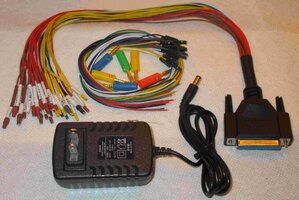
I'm sorry if this Topic has been neglected by me since March 20th, 2018... but there always seem to be other more pressing projects and repairs that must supersede a project like this that, while interesting for the sake of exploring these ideas and possibilities... are not absolutely necessary in "The Grand Scheme of Things" when it comes to keeping up with the stream of fixes we always face.
Nonetheless... due in part to my investigating and finding an inexpensive repair path for another GMTN Member facing the possible need to get a Replacement BCM courtesy some very reasonable offer(s) on eBay... He declined to act on purchasing what is arguably... the ONLY Best Way to pursue owning one: WHENEVER POSSIBLE... BUY THE COMPLETE BCM UNIT...LOCK, STOCK ...AND TWO SMOKING BARRELS! After giving him "First Dibs" on obtaining this SAME unit... Once he declined... I made a fair offer of $75.00 on eBay for the system and won this item.
If you reviewed my last post from back in March... after I obtained just the upper section Module of this unit... I was concerned about how I was going to be able to attach just that small portion of the entire system to the Bench-Top Harness.... and with the acquisition of the ENTIRE UNIT... Will all of those problems disappear because my only issues henceforth will be to sort out the Connector Wiring Pin-Outs? I will need to figure that problem out and answer these additional Questions:
(1) Which Wires (Pairs) from the various Modules can be connected in isolation to the Complete BCM and what method should be used to insulate all of the Cut Wires emanating from every single Connector that will be dormant during this powered set-up?
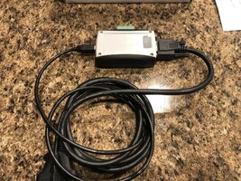
(2) What is the Primary Voltage DC and Amperage required to feed into the Large Red Power Input Wire of the Fuse/Relay Panel... and will the Power Source of the Tech 2 Clone AC/DC 12 Volt VDC @ 1 Amp be sufficient to power up BOTH the Bench Top PCM AND the Complete Bench Top BCM System?
(3) If not ...will using the much more robust Bench Top- External Power Supply I suggested and obtained for this contingency earlier in this Project be the Better Solution for Stable Power?
What is particularly important to mention about "Getting The Whole Ball of Wax" where the BCM is concerned was canonized in a comment made recently by @Mooseman that, "... Changing out and installing a BCM is NO TRIVIAL MATTER..." ... a complicated task which includes the requirement of using a Tech 2 Scanner to re-program in the VIN and get the BCM unit to be recognized by the PCM and logged onto the GM Data-Bus.
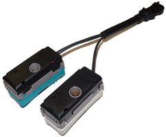
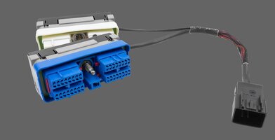
The attached images bear out the fact that THIS Full BCM System truly is"...Second Big Brain..." as @Mooseman basically described it and when held in the hand ...you can see that it is indeed... One, Big Chunk of Clunky Electronic Hardware... with numerous connectors,wire bundles and tangles of wiring.... and ALL of that Hardware that MUST be co-attached into a "Tesseract" -like Complete BCM System that includes Gold-Plated Flex Cabling, Multiple Discreet Harness Plugs and To and From Power to its very own Fuse and Relay Box ... all of which is ordinarily concealed from plain view where it hides under the Left Rear Passenger Seat. These attached images will bear out its odd Modular Complexity:
https://www.flickr.com/photos/126111508@N07/albums/72157675625128548


