ELM327 & Class 2 Serial Data

iddqd

Member
Oct 13, 2020
11
San Francisco, CA
My logs are gathered with Android App "Bluetooth Serial Terminal" by Kai Morich in the Google Playstore. Timestamp is an available option there.

View attachment 98096

Hey mate,

Sorry for a silence, I am a bit busy with work right now. I will get back to our research shortly.

Pavel
 

briesey

Member
Dec 8, 2020
1
Australia
Hey guys, I've been diving into class 2 data as an attempt to run a custom cluster in my 1985 Range Rover that I have converted to LS1-4L60 with the standard 0411 P59 ECM thats out of a 2003 Yukon that ran a LM7-4l60 combo.

The car runs and drives as a standalone conversion, and I have been reading data from the ECM via an ELM 327 blutooth dongle and the Torque app on my android phone. I have since purchased an ELM327 USB device and have read the data over the OBD Request-Reply through a python library and displayed the data on my laptop screen. This was a big step forward but the data was rather laggy. With the want to lower latency, would it be less laggy to read the class 2 data stream and pick out the values I need, then re-display? The only module in the steam is the ECM.

I guess my real question is, would I have to send a data request to the ECM to get things such as RPM, coolent temp, current gear selector position etc. And at the end of all this, will it be quicker then the PID method of data acquisition?

My ultimate goal is to read the data from the elm over serial with a microcontroller and re-broadcast the info over CAN bus to a late model Land Rover cluster (I've programmed modules to convert GM lan to Land Rover CAN bus before to run clusters in engine conversion). I'm very well acquainted with CAN, but the class 2 stuff is proving more convoluted haha.

Any info would be HUGELY apreciated!

Cheers!
 

TJBaker57

Original poster
Member
Aug 16, 2015
2,897
Colorado
have read the data over the OBD Request-Reply through a python library and displayed the data on my laptop screen.

By this do you refer to the use of service 22, Read Data by Parameter ID?


The only module in the steam is the ECM.

I have no experience with standalone systems. I would expect there to be a near constant stream of requests from the ECM for things such as "network status". This is what I have seen when I have observed a PCM on the bench with no BCM present. How is vehicle security, which is normally handled by the BCM overcome?


I guess my real question is, would I have to send a data request to the ECM to get things such as RPM, coolent temp, current gear selector position etc. And at the end of all this, will it be quicker then the PID method of data acquisition?

In the few vehicles I have tinkered with, RPM has been a direct line transmitted from the PCM to the cluster. I have thought this was done for speed/accuracy and perhaps to reduce network traffic on the class 2 bus? I see RPM transmitted on the bus but only sporadically. Some other data points appear to be transmitted on the serial class 2 bus only when there is a change in value.

I suspect that the speed would be the same where either message at its basic level is just another message on the bus and goes through the same message arbitration, etc.

Now if I understand correctly you are doing these things programmatically, right? There is another way to get data from a module. Test instruments such as the Tech 2 use another service, '2A' as opposed to service 22. With service 22 a single request is made and a single response is received. With 2A a request is made to return a data 'packet' which has been configured by the use of another service. The packet can hold up to 6 bytes of data. The Tech 2 uses service 2C to configure the data packet(s). Additionally these packets can be streamed at various speeds using a sub function of service 2A. This streaming would require the sending of a 'test tool present' message periodically to keep the stream active, otherwise the stream lasts for just a few seconds.

Now here is the thing I don't know. For some operations a test tool alters the normal operation of the module. For example, when entering into the EBCM to view data, the Tech 2 warns that ABS will not be available. I do not know if this is the result of a specific command sent by the Tech 2 or is it simply calling up data by the use service 2C/2A?? I would not want to disrupt normal module operations where they may interfere with matters of safety. This looks not to be a concern in your specific case as there is but the one module, the ECM.

If we want to discuss the use of service 2C, 2A for polling data we should start another thread as I don't think there is anything existing in that realm here in the forums.
 

TJBaker57

Original poster
Member
Aug 16, 2015
2,897
Colorado
Thus far I have resolved or at least identified the following values in the class 2 serial data:

*Front Wheel Speed
*Vehicle Speed
*Odometer
*Incremental Odometer??

Well it took me quite some time, and several attempts but I finally cracked the "incremental odometer" nut. My 02 Trailblazer with 4.2 & P10 PCM does not report this value but my 05 Yukon with LM7 and I believe a P59 PCM does. The value is a 2 byte value that rolls over and reports miles at a resolution of 4000 bits per mile. The frequency of reports is about 4 times per mile.

Might this be the source of the odometer value accumulated in the IPC?? Or elsewhere? I have no idea.
 

jim carrier

Member
Jan 13, 2021
18
canada
like i said in the old thread, im trying to ask data out of the elm 327. im currently using hyperterminal to isolate data but it seem like i cant ask for those value back.


68 EA 10 0A 01 AE

he sample you posted "68 EA 10 0A 01 AE" breaks down as this...

68 means a priority 3 type 8 message.

EA (&EB) are the Primary ID Pair for the functional address for "Displays".

10 is the node address of the source of the message, in this case the PCM.

0A is a secondary ID of the Functional address Primary ID pair of EA & EB, (Displays). I do not know the official name of this secondary ID parameter "0A" but you are correct that it carries the data of what the current gear selection is to be displayed by the instrument cluster.

01 is the data byte. I have most often seen this to be 01=P, 02=R, 03=N, 09=D, 08=D3, 07=D2, 06=D1, however I have also seen 00 as P under certain circumstances.

AE is a checksum only. (Not of any value to us)
What engine and what ECM/PCM are you working with?
its on a p59 ecm, 2004 silverado with the 6.0 as for data byte you are right on touch thats exactly what i got figured. but like i said i dont seem to be able to "ask" ecm for those data like i would do for a regular pid, and then feed them back to torque/real dash.

im wondering if im just lacking of decode knowledge or if its just a "poping message" on bus whenever you put the gear on. im pretty sure it dont but well.. i mean original cluster would have to catch it everytime else it wouldnt display right ?. there gotta be a back and forth operation...


isnt there a way for those software to listen to specific data and use them ? that would solve a lot of trouble.

else i like the way you can read the code, is there any pdf / web that i could read to understand code better ?

i dont know if you have time to scool me up but i would be really thanksfull . i can pay too if you want, thats some new thing to me and i really want to dig in further into the stock ecm before going the easy aftermarket way...
 
Last edited:

TJBaker57

Original poster
Member
Aug 16, 2015
2,897
Colorado
its on a p59 ecm, 2004 silverado with the 6.0

I have a P59 on a 2005 5.3 LM7. Hopefully what works on mine will work on yours.

I would like to know what your current configuration is in Torque Pro. And yes, you need the Pro version, not the free "lite" version for this. Have you loaded the GM specific set of extended/enhanced/extra PIDs? Do you get any of the other data parameters from these "[GM]" PIDs. I ask this in order to confirm that the Torque Pro app is properly communicating with the vehicle.


but like i said i dont seem to be able to "ask" ecm for those data like i would do for a regular pid, and then feed them back to torque/real dash.

im wondering if im just lacking of decode knowledge or if its just a "poping message" on bus whenever you put the gear on. im pretty sure it dont but well.. i mean original cluster would have to catch it everytime else it wouldnt display right ?. there gotta be a back and forth operation...

Well,,, No. For these purposes there is generally NOT a controlled back and forth, request/answer sort of traffic. For most of these data points the information is broadcast either on a periodic interval or only on a change of status. For example, if you move the shifter the PCM detects the change in the transmission range sensor and then broadcasts a message with this new position. The message is addressed NOT to a specific device (like the network address of the instrument cluster) but instead the message is sent to what is termed a "functional address". A functional address means the message is identified as having to do with a specific system, like the displays, or the fuel system, or parameters related to the HVAC, or even the tires. So in the case of a transmission range position change the PCM sends a message out addressed to "Displays" and any module that needs such information will be monitoring the message traffic looking for just such a message. The instrument cluster will recognize that this message has data it should display and will process the message and make the needed change to the shift position indicator. Some messages also sent to the "Displays" address might be picked up by the radio for display on its screen.

Getting back to using Torque Pro using this communication method... I have had some success doing this. But it is good to remember that Torque Pro was never intended to work this way. Yes, there is a specific message format that would need to be entered into Torque Pro to do a request for the data. It is somewhat complicated. Examples are seen in a few posts on this thread. One such example comes to mind where a fellow with a corvette was trying to call up tire pressure information.

This may seem confusing but I am going to jump back to the Torque PID thread to discuss the use of true PIDs as this thread is primarily intended to discuss Class 2 serial message traffic, not the use of Torque and PIDs. True enough, there will be a great deal of overlap between the two threads but I am going to at least try to keep the two threads focused on the thread title subjects as best I can.
 

ssndk

Member
Apr 2, 2021
2
Sweden
Hi,

I've been reading this thread with great interest! I have been wanting to do a project where I replace all the warning chime sounds in my 2007 Corvette. I upgraded the head unit recently and by that you lose all the warning chimes (the old head unit took care of those). I got a converter, the RP5-GM11, that interfaces/converts many of the functionalities from the old head unit. It even comes with a separate chime module, that sounds awful though.

My plan is to splice in an arduino or rpi to the class 2 serial line on the head unit and listen for audible warning commands. From J2178-4 I can see there is an address for audible warnings (96/97), but in order to be able to play different chimes based on different warnings (door ajar, seat belt etc) I need to know how to identify and differentiate the warnings. I have not been able to find any detailed information on how these warnings are processed. Do you know where I could maybe find additional information on this?

Thanks for this thread! It's really getting me started.

Soren
 

TJBaker57

Original poster
Member
Aug 16, 2015
2,897
Colorado
Hi,

I've been reading this thread with great interest! I have been wanting to do a project where I replace all the warning chime sounds in my 2007 Corvette. I upgraded the head unit recently and by that you lose all the warning chimes (the old head unit took care of those). I got a converter, the RP5-GM11, that interfaces/converts many of the functionalities from the old head unit. It even comes with a separate chime module, that sounds awful though.

My plan is to splice in an arduino or rpi to the class 2 serial line on the head unit and listen for audible warning commands. From J2178-4 I can see there is an address for audible warnings (96/97), but in order to be able to play different chimes based on different warnings (door ajar, seat belt etc) I need to know how to identify and differentiate the warnings. I have not been able to find any detailed information on how these warnings are processed. Do you know where I could maybe find additional information on this?

Thanks for this thread! It's really getting me started.

Soren
We might not get you all the way there but we can surely set you off in the right direction.

Some of what you will need is an understanding of "extended addressing" it is in the J2178-4 you have, in the 1999 version have a look at I think it's page 34. You will see a listing of extended address assignments for doors and door locks. So in the case of your example of door ajar switches. Here is a sample snippet from a spreadsheet of mine...

Screenshot_20210402-165227.png

Have a look at row 12. There we have a priority 4, type 10 message which uses extended addressing. The message is from module A1, the passenger door module and the target of the message is C7, External Access which you will find in J2178-4. Data byte 1 is a secondary ID of 21 which is 'ajar sw active', also found in J2178-4 Table 34 of the 1999 edition. In Table 34 it can be seen that this secondary ID of '21' uses external addressing listed as 8.5. That is a typo, the ext addr assignments are actually in section 9, not 8 so they are really at 9.5! So going down to section 9, find Table 56 and we will find the next data byte, the extended address of '26' is for the passenger side front door.

I think I have done a horrible job of explaining this here but just maybe you get the gist of it?

This much just identifes what the message is for, it still leaves the deciphering of is the switch open or closed to be discussed.
 

ssndk

Member
Apr 2, 2021
2
Sweden
We might not get you all the way there but we can surely set you off in the right direction.

Some of what you will need is an understanding of "extended addressing" it is in the J2178-4 you have, in the 1999 version have a look at I think it's page 34. You will see a listing of extended address assignments for doors and door locks. So in the case of your example of door ajar switches. Here is a sample snippet from a spreadsheet of mine...

View attachment 100048

Have a look at row 12. There we have a priority 4, type 10 message which uses extended addressing. The message is from module A1, the passenger door module and the target of the message is C7, External Access which you will find in J2178-4. Data byte 1 is a secondary ID of 21 which is 'ajar sw active', also found in J2178-4 Table 34 of the 1999 edition. In Table 34 it can be seen that this secondary ID of '21' uses external addressing listed as 8.5. That is a typo, the ext addr assignments are actually in section 9, not 8 so they are really at 9.5! So going down to section 9, find Table 56 and we will find the next data byte, the extended address of '26' is for the passenger side front door.

I think I have done a horrible job of explaining this here but just maybe you get the gist of it?

This much just identifes what the message is for, it still leaves the deciphering of is the switch open or closed to be discussed.

Yes, makes sense, I can see how I can verify the door position this way (with a bit of reverse engineering with the door open and closed.). Where did you originally see that A1 is the passenger door?

One thing that I noticed in your OBD2_Class2_TrailBlazer_Startup is line 28 to 34, specifically 30 and 31, it has a target address of 96 and 97 (AudibleWarning). I guess all data bytes are unknown information? What I was hoping for was that the logic of what audible warnings get raised are done somewhere else and all I have to do is catch calls for audible warnings and then decipher what triggered it. I will of course check this on my car, but looks like line 28 and down (maybe even line 26 and down) the process causing an audible warning is taking place.

One thing that would be great is to script the conversion from the raw data to the format in your excel sheet. I think I will look into this as well. It would make debugging a lot easier. Thanks again!
 

TJBaker57

Original poster
Member
Aug 16, 2015
2,897
Colorado
Where did you originally see that A1 is the passenger door?
This was a combination of first seeing this post which very well may be where I got my start on this endeavor....


And then I captured data from my vehicle and using spreadsheet formulas I isolated a listing of module addresses active in my vehicle. The next step was some simple testing where I would monitor an address on the bus and say press a button like a door lock and see what address sent data out. If you look at the tab 'Nodes' in the spreadsheet there is a listing of what I have identified in my vehicles.
 

TJBaker57

Original poster
Member
Aug 16, 2015
2,897
Colorado
One thing that I noticed in your OBD2_Class2_TrailBlazer_Startup is line 28 to 34, specifically 30 and 31, it has a target address of 96 and 97 (AudibleWarning).


I have a problem in that I have many copies of that spreadsheet. The one shared on this thread at post #117 doesn't have that line in the location you mentioned?? Are you using that link from post #117?

Just this morning I did some testing and I can now turn the chime on and off in my truck by sending the appropriate message.

I added a short data sample to the spreadsheet linked in post #117 as an example of chimes turning on and off and switched the spreadsheet 'Output' tab to display that data sample. This is done by changing the value in cell A1 of the 'Output' tab to correspond to the column letter in tab 'Sheet 1' that contains the desired properly formatted data log and giving it a minute or two to switch over.
 

TJBaker57

Original poster
Member
Aug 16, 2015
2,897
Colorado
Just for the fun of it....

Using an OBD2 adapter and a serial terminal app like Bluetooth Serial Terminal by Kai Morich...

Set your header like this...

ATSH6896F1

Then send this message...

915D01

Your chime will sound once. The final hex byte is a count of the number of chimes to send. Send 915D06 and you will get six chimes, send 915D10 and you will get 16 chimes (it's hexadecimal, remember).

And if you send 915DFF you will be sending chimes for about a minute and a half!!

To cancel if you don't feel the need to wait you must send 115DFF or 115D00 or the like. The last byte doesn't really matter here because the '11' in place of the '91' is turning it off instead of on.

 
Last edited:
  • Like
Reactions: Mooseman

BriggTrim

Member
Aug 12, 2021
1
California, USA
Hi...I haven't had a chance to play with it however. I ought to numerous ventures on my work area at the minute but I did message NSFW around it since it is his github.. Arranging on attempting it out within the following few weeks. I have tried matafonoff's J1850VPW library it didn't work. I Moreover attempted connorwm's extend on github. His optocoupler circuit didn't work so I didn't bother with the script he clearly never tried it.
 

mike66175

Member
Apr 24, 2022
1
The Netherlands
Hi All, Foremost, I want to thank everyone for going to such detail on the Class 2 serial data for GM trucks.

Buy I need a little help with sending some "commands" to the modules first a little background information (I want to go in detail in my own thread),

A few yes back, I bought a Chevrolet Avalanche II from 2005 equipped with OnStar, but unfortunately this does not work in The Netherlands, So I have been planning on how to overcome this problem at first I wanted to emulate button presses by connecting to the buttons itself on the HVAC unit for example,
But I came across "Bypass modules" that can control existing features by using the Class 2 :smile:
So I thought if after market devices can do this, then I would be able to do so too.

After a lot of time reading online (including this thread) and trying to understand the j1850 protocol, I started to probe around in the console of the ELM327 and got the easy stuff working pretty quickly just by sniff the traffic for example locking and unlocking the doors:

68 C4 97 -> 11 00 01 UNLOCK DRIVER
-> 11 1F 1F LOCK
-> 11 00 1E UNLOCK ALL
(note, I used the OnStar address, so I don't have duplicate addresses on the bus)

But here is where I get stuck, I Would like to turn on the HVAC, but I don't really understand how to build the "message"

If I take a look on 
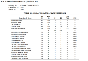
J2178-4 page 23 it talks about Primary ID, Command ID, Status ID: and then a table describing the different "functions" I would do the following, thinking the message type should be 10 priority 3, But I am not sure if this is correct :

Set the header > AT SH 6A B2 F1
Send message > 0A ?? ?? Then I am lost. (0A should be Set temp)

I hope someone can point me in the right direction :rolleyes:
 

Attachments

  • Climate Control (HVAC)—.png
    Climate Control (HVAC)—.png
    94.8 KB · Views: 27
  • Like
Reactions: santon

TNT3530

Member
Sep 17, 2021
1
USA
Does this work on any older OBD2 GM car? Ive gone through two bluetooth adapters and neither will read from my 1998 Firebird. It either just echos the ATMA command or gets stuck on searching... I know at least one of the adapters supports MA as it works (though sporadically) on my CAN bus car.
 

azswiss

Member
May 23, 2021
860
Tempe, AZ
Most GM cars produced in 1996-2003 use the J1850-VPW interface (ELM327 protocol 2). Before attempting to monitor you might want to do a reset by entering ATZ and then set the read protocol to automatic by entering ATSPA2 (this enables auto detect, but starts off with J1850-VPW). Alternatively you could specify J1850-VPW directly by entering ATSP2.
 
Last edited:

santon

Member
Jun 3, 2020
94
Israel
Hi all,
I want to implement the Arduino for sending Serial class II data. There is a matafonoff's J1850-VPW on Github written for Chrysler and mentioned above. Does this library works on TB or on GM in general? I noticed at least 2 suspicious things with this library: 1) the hardware interface is inverting, i.e., the HIGH signals will appear LOW; 2) the baud rate in the example code is 11.52kbps while in J1850-VPW it should be 10.4kbps. Is there any other working library and interface for Arduino?
 

santon

Member
Jun 3, 2020
94
Israel
Hello,
I am trying to figure out the J1850VPW commands for door lock/unlock and windows roll up for 2006 Chevy Trailblazer. I recorded some messages during doors locking/unlocking and window rolling up/down. Based on bytes 2 and 3, I believe these commands are related to the doors and windows:
Doors:
68 C4 40 11 1F 1F EF
68 C4 40 11 00 01 93
68 C4 40 11 00 1F F8
(since $C4 door locks, $40 is a BCM).

Windows:
68 CB A0 09 02 11 00 00 70 41
68 CB A0 09 08 11 00 00 70 E2
68 CB A0 09 04 11 00 00 70 20
68 CB A0 09 01 21 00 00 70 90
68 CB A0 09 01 41 00 00 70 4E
68 CB A0 09 01 12 00 00 70 45
68 CB A0 09 01 14 00 00 70 2C
(since $CB is windows, $A0 is driver module)
However, I am not sure about the meaning of the following bytes, and how they are related to the particular door or window. Also, should I change anything while sending a command to the car, mimicking the activation of the door locks or windows? For example, should I use byte 2 [$F1] (scan tool) instead of [$40] or [$A0], or anything else?
 
Last edited:

Mooseman

Moderator
Dec 4, 2011
25,257
Ottawa, ON
@TJBaker57 is currently MIA on a cross country trek. Hopefully someone else is able to answer.
 
  • Like
Reactions: santon

azswiss

Member
May 23, 2021
860
Tempe, AZ
As @Mooseman says, @TJBaker is the definitive source on all things ELM327/Class 2 Serial Data. That said, after a little experimentation I got the following data by opening the locks using the key fob and by using the door lock/unlock switch.

Capture.JPG

The key command sequence for each method is circled.

Using a serial terminal app I can open the locks by replicating the command string generated by using the lock switch on the driver's side door: 8A C5 A0 A1 22 5F

Additional details on J1850 messaging structure & addressing can be found here:

SAE J2178-1 Revised MAR1999

SAE J2178-2 Revised MAR1999

SAE J2178-3 Revised MAR1999

SAE J2178-4 Revised MAR1999

Edit: This data is from a 2003 Suburban so there may be some differences versus your vehicle.
 
Last edited:
  • Like
Reactions: santon and Mooseman

santon

Member
Jun 3, 2020
94
Israel
Thanks to @azswiss and @mike66175, I was able to lock and unlock the doors. Here are the commands that I used:
AT SH 68 C4 F1
11 1F 1F >>> lock all doors

AT SH 68 C4 F1
11 00 1F >>> unlock all doors

I was also able to roll down and up the front right window:

AT SH 68 CB F1
09 08 11 00 00 70 >>> window roll down

AT SH 68 CB F1
09 04 11 00 00 70 >>> window roll up

I need to find a way to do the same thing with other 3 windows. I believe the bytes 5 and 6 need to be changed. However, I don't understand how to change these bytes yet.
 

azswiss

Member
May 23, 2021
860
Tempe, AZ
Windows:
68 CB A0 09 02 11 00 00 70 41
68 CB A0 09 08 11 00 00 70 E2
68 CB A0 09 04 11 00 00 70 20
68 CB A0 09 01 21 00 00 70 90
68 CB A0 09 01 41 00 00 70 4E
68 CB A0 09 01 12 00 00 70 45
68 CB A0 09 01 14 00 00 70 2C
Assuming you have most of the data already so this will be a trial & error exercise. Monitor the bus traffic as you cycle each window up & down using the switches on the driver's door with the key on and the engine off (minimizes bus traffic). Judging from the data it looks like A0 is the Drivers Door Module and CB is the Windows (not sure if it is a Command, Request or Query). Looking forward to hearing about your observations.
 

santon

Member
Jun 3, 2020
94
Israel
@azswiss, among these codes, only the following were working:

68 CB F1 09 02 11 00 00 70 (rolls down the right front window)
68 CB F1 09 08 11 00 00 70 (also rolls down the right front window)
68 CB A0 09 04 11 00 00 70 (rolls up the right front window).

It seems like byte 2 $CB is a status request. It should probably be $CA (command).
However, I don't see $CA in the sniffed data. In general, my data seems weird since I cycled the windows in this order: left front, right front, left rear, right rear.
Thanks!
 

azswiss

Member
May 23, 2021
860
Tempe, AZ
I observed a similar phenomenon when I unlocked the door from the lock switch on the driver's side door (8A C5 A0 A1 22 5F); byte 2 (C5) is Door Locks Status yet it opens the door versus an expected byte 2 value of C4 - Door Locks Command.

Question: what data do you see when cycling just one window other than the right front?

I will experiment with the windows tomorrow and post what I find.
 

santon

Member
Jun 3, 2020
94
Israel
Question: what data do you see when cycling just one window other than the right front?

The data that I posted above (post #138) was sniffed during cycling all 4 windows, from the switches of the driver door module, in a following order: left front, right front, left rear, right rear.

I also tried to cycle right front window from its switch on the right front door module. Maybe this does not make sense since the window motor probably receive the voltage directly from its module. Here are the commands:

8A CA A0 03 28 C1
8A CA A0 03 28 C1
8A CB A1 03 26 75
8A CB 40 03 28 CC
6A CA A0 03 26 1A
 

azswiss

Member
May 23, 2021
860
Tempe, AZ
Note: Post edited to reflect new data

I monitored the data while opening & closing the windows starting with Front Left Driver, Front Right & Rear Left and then holding the button for several seconds. (cannot use Rear Right as the motor is broken). I then parsed the data thru Excel to eliminate the non-window data. Here is what I observed:

All window data traffic is of the form of 68 CB A0 09 XX YY 00 00 70 QQ
Data Byte 2 (XX) = 01, 02, 04
Data Byte 3 (YY) = 11, 12, 14, 21, 41
Check Byte (QQ)

Holding the switch to either lower or raise the windows results in multiple instances of the same command which leads me to suspect that it represents an incremental movement.

My analysis suggests that Bytes 2 & 3 are combined to produce the the desired motion (Up, Down) in the desired window (front/rear, left/right).

Front Left Down: 68 CB A0 09 02 11 00 00 70 41
Front Left Up: 68 CB A0 09 04 11 00 00 70 20

Front Right Down: 68 CB A0 09 01 12 00 00 70 45
Front Right Up: 68 CB A0 09 01 21 00 00 70 90

When a switch is released the following string is sent one time:
68 CB A0 09 01 11 00 00 70 FF
 
Last edited:

santon

Member
Jun 3, 2020
94
Israel
My analysis suggests that Bytes 2 & 3 are combined to produce the the desired motion (Up, Down) in the desired window (front/rear, left/right).
I will try to experiment with these bytes next week.

Some things are still not clear. For example, in my case, the command 68 CB F1 09 02 11 00 00 70 that I sent from the OBD adapter moved the front right window down. You observed that the same message 68 CB A0 09 02 11 00 00 70 41 was running during the rolling down the front left window. Also, I was expecting the second byte of the header be CA (load command) and not CB (status request).
 

santon

Member
Jun 3, 2020
94
Israel
All window data traffic is of the form of 68 CB A0 09 XX YY 00 00 70 QQ
Data Byte 2 (XX) = 01, 02, 04
Data Byte 3 (YY) = 11, 12, 14, 21, 41
Check Byte (QQ)
I tried different combinations, substituting byte 2 and 3 with these numbers. I can only move the front right window with several different commands (i.e., there is more than one command for the up and down movement). Today we (me and my friend) did the following: we hooked up the Arduino setup that I built for J1850 sniffing, to the pin#2 of the OBD port. Also,we connected the friend's GM Tech2 tool to the OBD port and activated the front windows from the GM Tech2 menu. At the same time, we montored the traffic on the serial data bus with the Arduino. Amoung the sniffed commands, we found two commands that moves the front left and right windows up:
6C A0 F1 AE 02 00 00 00 00 01 01 (front left window up)
6C A1 F1 AE 02 00 00 00 00 01 01 (front right window up).
These are the commands that GM Tech tool ($F1) sent to driver module ($A0) and the passenger module ($A1). These commands actually work - we were able to activate the windows by sending these commands to the car. All I need to find is the same commands for the rear windows. Unfortunately, we did not find the possibility to control the rear windows from GM Tech. I believe it could be done since these windows could be controlled from the drivers module, and this control is probably also done through Class 2 serial data bus. The electrical diagram does not show the Class 2 serial connection of the rear door modules. However, these modules are connected to the BCM with the "LR Lockout Control" and "RR Lockout Control" wires so I suppose there should be a command to BCM that can activate these windows.
 
Last edited:

santon

Member
Jun 3, 2020
94
Israel
An update: I managed to figure out the commands for rolling up the rear windows. If anybody is interested, here the commands:
6C 40 F1 AE 01 00 00 01 01 08 08 (rear left up)
6C 40 F1 AE 01 00 00 00 00 81 81 (rear right up)
The commands are sent to BCM ($40).
 
Last edited:
  • Like
Reactions: azswiss

gigawatts

Member
Apr 30, 2022
1
Earth
Anyone know what command(s) to send to trigger the ABS auto-bleed / test function? I know the Tech2 and clones can do this, but I don't have one, figured the ELM327 should be able to send the same command.

If someone wants to sniff what command the Tech2 sends out during this test, that would be awesome!
 
Last edited:

TJBaker57

Original poster
Member
Aug 16, 2015
2,897
Colorado
An update: I managed to figure out the commands for rolling up the rear windows. If anybody is interested, here the commands:
6C 40 F1 AE 01 00 00 01 01 08 08 (rear left up)
6C 40 F1 AE 01 00 00 00 00 81 81 (rear right up)
The commands are sent to BCM ($40).


A word of caution here....

These two commands seen here are using service AE, "request device control". This is vastly different then what was previously discussed in this thread and detailed in SAE J2178.

Service AE is what a Tech 2 or equivalent scantool would use to test out various outputs of a module.

While the specifcations laid out in SAE J2178 may be the same across many platforms/manufacturers the details of a service AE request can vary greatly perhaps even within a platform? And if the request is executed there is no telling what might happen as these details are proprietary and at the whims of GM as opposed to an SAE standard. The upshot is that what works on one year/make/model may do something entirely different on another.

I have explored a bunch of these and have done things like activate an injector or disable one, turn on the fuel pump, engage the front axle disconnect, close the EVAP vent valve, move HVAC actuators, activate the ABS pump and so on. Two reasons I haven't posted about this are 1: I have no clue whether the commands that work on my truck would work on others and 2: this is likely highly proprietary information.

My advice to anyone experimenting with service AE messages is proceed with a good deal of caution.
 
  • Like
Reactions: santon

04colyZQ8

Member
Apr 23, 2019
19
Bc
Hey guys we’re can I find that excel template that organizes the class 2 messages so nicely?

I was trying to get the lock unlock to work on my 04 Colorado, but because we don’t have an external door lock module those posted earlier don’t work, and my bcm class 2 network is dead until key on.

Is there a wakeup message to be sent ?
 

TJBaker57

Original poster
Member
Aug 16, 2015
2,897
Colorado
because we don’t have an external door lock module

If the vehicle has (or had) a keyless entry (keyfob) then the vehicle must have a module that receives the signal from the keyfob. That module would then send the bus wakeup message and after that it would send the message that causes the BCM to activate the door unlock relay(s).

Have you monitored and recorded the serial data traffic when pressing a keyfob door unlock button?
 

04colyZQ8

Member
Apr 23, 2019
19
Bc
If the vehicle has (or had) a keyless entry (keyfob) then the vehicle must have a module that receives the signal from the keyfob. That module would then send the bus wakeup message and after that it would send the message that causes the BCM to activate the door unlock relay(s).

Have you monitored and recorded the serial data traffic when pressing a keyfob door unlock button?
No it’s all internal to to the bcm, bcm has rfa antenna built in, and it’s directly wired to the door locks, no other modules.

I can lock and unlock via mode AE, tech 2 commands but the bcm has to be awake first!

Tried sending 68 FF F0 02 this should wake up all nodes right?

Tried sending 28 FF F0 28 00 thought this also woke up modules than they report the address. But that also didn’t wake it up.

Btw bcm is also power mod master and is responsible for waking up all other non switched class 2 modules such as the cluster
 

Mooseman

Moderator
Dec 4, 2011
25,257
Ottawa, ON
No it’s all internal to to the bcm, bcm has rfa antenna built in, and it’s directly wired to the door locks, no other modules.
Uh no. The RKE receiver is in the tailgate control module (TCM) and it sends the command to the BCM to lock/unlock, at least on the 360/370.
 

TJBaker57

Original poster
Member
Aug 16, 2015
2,897
Colorado
Tried sending 68 FF F0 02 this should wake up all nodes right?

In SAE J2178 that secondary ID of "02" is defined as "bus wake-up". In a Trailblazer the first byte is 88 instead of the 68 you have there but I don't imagine message priority should matter all that much here. Also I don't often see the address "F0" used, the most common being "F1" though my Tech II does use "F0" here and there.

In a Trailblazer that bus wake-up message is most often sent by either a door module or the liftgate module and is followed by a power mode message from our BCM and that as you know gets all the other modules into the desired operating state. Your Colorado is of course different in that you don't have such modules.

How are you sending your messages? (what hardware & software(s) etc)


Tried sending 28 FF F0 28 00 thought this also woke up modules than they report the address. But that also didn’t wake it up.

Where did you see the secondary ID of "28" used with the status ID of "FF"??

Have you tried a header of "6C FE F1" with a secondary ID of "20"? I sometimes use that twice to get modules to come up.
 

04colyZQ8

Member
Apr 23, 2019
19
Bc
Uh no. The RKE receiver is in the tailgate control module (TCM) and it sends the command to the BCM to lock/unlock, at least on the 360/370.
Sorry I’m not meaning to confuse anyone! It’s my fault for not properly declaring my project ...
2004 Colorado with 07 ctsv pcm v8 swap , and 08 Colorado bcm/theft deterrent module swap.
 

04colyZQ8

Member
Apr 23, 2019
19
Bc
In SAE J2178 that secondary ID of "02" is defined as "bus wake-up". In a Trailblazer the first byte is 88 instead of the 68 you have there but I don't imagine message priority should matter all that much here. Also I don't often see the address "F0" used, the most common being "F1" though my Tech II does use "F0" here and there.

In a Trailblazer that bus wake-up message is most often sent by either a door module or the liftgate module and is followed by a power mode message from our BCM and that as you know gets all the other modules into the desired operating state. Your Colorado is of course different in that you don't have such modules.

How are you sending your messages? (what hardware & software(s) etc)


Where did you see the secondary ID of "28" used with the status ID of "FF"??

Have you tried a header of "6C FE F1" with a secondary ID of "20"? I sometimes use that twice to get modules to come up.
So send
Atsh 6c fe f1
20

?

I see 28 used for high priority like ignition events so I tried it and it worked. But ignition seeks to have to be on?
 

04colyZQ8

Member
Apr 23, 2019
19
Bc
So send
Atsh 6c fe f1
20

?

I see 28 used for high priority like ignition events so I tried it and it worked. But ignition seeks to have to be on?
Oh and I am using putty with a cheap Ford elm327 at 38400 baud.

I also have a mongoose pro, avt 852, elm329, efi live, tuner cat, hp tuners, universal patcher master, avt term, vpw logger, pcmhammer ip hammer and my own python and c# scripts, plus some C programs.

Trouble with coddling the elm is getting the timing just right, so long a pause between commands controller times out.. to short a time elm sends garbage ..
 

04colyZQ8

Member
Apr 23, 2019
19
Bc
Ok I made some progress..

My obd2 port was only hot switched on, made pin 16 Hpt at all times now modules wake up, using several commands!

Also logged this
88 C7 40 20 12 happens when I press lock on the key fob
88 C7 40 20 11 happens when I press unlock on the key fob

Trouble is it’s not super reliable and I can’t replicate it by sending it on my elm327 nothing happens!

I thought it’s maybe arming or unlocking but it’s not doing anything?

Any ideas?
 

Forum Statistics

Threads
23,273
Posts
637,488
Members
18,472
Latest member
MissCrutcher