ELM327 & Class 2 Serial Data

AmpOverload

Member
Jul 10, 2023
148
USA
I believe there is a message running on the network since the instrument cluster has the coolant temperature gauge.
Then you should see a "49 10 10" somewhere in your scans, assuming they cover a long-enough time period. (Things like ECT and transmission fluid temperature will not be seen very often since they obviously don't change as fast as something like engine speed.)

Where can I find the detailed info on all of the bytes of the serial commands? I found this website but it is not so detailed (or I don't understand this info enough).
That website you linked to is a good starting place, but your question is too vague to answer. There are way too many cases of "serial commands" to give you a sensible, succinct reply. Are you interested in sending commands to make queries of well-documented, non-manufacturer-specific vehicle parameters (e.g. engine coolant temperature, mass air flow, etc)? If so, then you want Mode/Service $01 and should probably start by reading SAE J1979. If you mean something else, please clarify.

OK, an update -I finally found the messages 68 49 10 10 XX CS. Thanks!
Excellent! (I had already composed the above reply before I saw this post of yours, so I went ahead and included that reply anyway.)
 

santon

Member
Jun 3, 2020
113
Israel
Are you interested in sending commands to make queries of well-documented, non-manufacturer-specific vehicle parameters (e.g. engine coolant temperature, mass air flow, etc)? If so, then you want Mode/Service $01 and should probably start by reading SAE J1979. If you mean something else, please clarify.
Yes, I meant the document that I could use as a "dictionary" to interpret the commands that I get from the vehicle network and create my own commands to the car. It seems that SAE J1979 is such a document. Thanks a lot.
 

azswiss

Member
May 23, 2021
984
Tempe, AZ
Some additional reading material - J2178: Class B Data Communication Network Messages
Part 1: Detailed Header Formats and Physical Address Assignments
Part 2: Data Parameter Definitions
Part 3: Frame IDs for Single-Byte Forms of Headers
Part 4: Message Definitions for Three Byte Headers
 

Attachments

  • SAE-J2178-1-1999.pdf
    237.2 KB · Views: 12
  • SAE-J2178-2-1999.pdf
    379.4 KB · Views: 9
  • SAE-J2178-3-1999.pdf
    806.2 KB · Views: 7
  • SAE-J2178-4-1999.pdf
    198.6 KB · Views: 10

TJBaker57

Original poster
Lifetime VIP Donor
Member
Aug 16, 2015
3,076
Colorado
OK, an update -I finally found the messages 68 49 10 10 XX CS. Thanks!

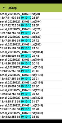
I was getting ready to post up a reply and I see @AmpOverload and @azswiss took up the reins and jumped in and you have it already solved! I am not really surprised at that. Anyway, Here is a screenshot from that same data file I used just recently showing Engine Coolant Temperature messages...


Screenshot_20240429-141920_aGrep.jpg
 

TJBaker57

Original poster
Lifetime VIP Donor
Member
Aug 16, 2015
3,076
Colorado
Where can I find the detailed info on all of the bytes of the serial commands? I found this website but it is not so detailed (or I don't understand this info enough).


I think my journey into this arena began with that website / document many years ago.


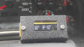
I am building a small setup with an OLED display - a gear position indicator. Attached is the picture of the setup. Here is the video of the gear indicator in action. The final version will be smaller, and I am going to put a display in some visible place on the dash.

I for one would be very interested in details of your project. Particularly with the circuitry and Arduino code. I cobbled together both circuitry and code snippets from many sources for my J1850 project. Not having any formal training in programming or electronics resulted in me spending a lot of time getting something that works! Perhaps if you have the time you could post over in the Arduino Chat thread??

https://gmtnation.com/forums/threads/arduino-chat.22775/
 

bryanbc

Member
May 20, 2024
2
California
Hi all,

I am new here, I have a 2005 GMC Sierra and a 2004 GMC Yukon Xl. With the heat starting to move in I wanted to be able to control my AC remotely, as I’m installing remote start in the future. While I could hardwire the HVAC to turn on I want a bit of a more elegant solution. I found this thread and I think tapping into the serial data and sending a command through there will be the perfect solution. I could wire in with an Arduino and have my alarm fob send commands through the auxillary outputs. Or through my phone Hopefully I can program the heated seats as well in the winter, as well as the folding mirrors. Basically I want to give it the functions that the newer 2007 and up have. I think the member iddqd had a similar goal.

I bought an OBD adapter from QUALLY on Amazon, unfortunately I get an Unknown Driver message and my dash and radio turn off, so I’m guessing the serial port gets shorted out on the adapter. It worked fine the first time with but I couldn’t establish a connection with the Serial Bluetooth Terminal.

Backstory aside, any recommendations on an ODB bluetooth scanner that can send commands and receive data? And any recommendations on communicating with it on windows or Mac?
 

TJBaker57

Original poster
Lifetime VIP Donor
Member
Aug 16, 2015
3,076
Colorado
any recommendations on an ODB bluetooth scanner that can send commands and receive data?


I have good luck with devices from Veepeak which I usually buy on Amazon.

The device you bought 'should' be capable of doing the same things.

What app(s) have you tried with your device?

unfortunately I get an Unknown Driver message

This much sounds like your device is interfering with the serial data network. Perhaps it is defective. I assume you only get the "Unknown Driver" message while the device is plugged into the DLC?

I think tapping into the serial data and sending a command through there will be the perfect solution.

Easier said than done I'm afraid. Any module you wish to command via serial data needs to have been designed and programmed to respond to such message/commands. In the case of the HVAC control module pretty much all the operational switches/buttons are integral to the module itself and thus have no need to monitor and react/respond to serial messages.

An exception is my 2002 Trailblazer. It has steering wheel switches for the HVAC fan speed and drivers temperature settings. These steering wheel switches wire to the BCM and thus the BCM must send messages to the HVAC module to adjust these two parameters.

Even so, there is no ON/OFF or Mode switching available on the steering wheel so the best I could do is adjust the fan speed or drivers temperature settings.

Then also is the range of a bluetooth connection. Just about 30' is all I could expect.

Now I suppose I could use a WiFi OBD adapter that could give me better range. And I could build an Arduino project to recieve serial data messages and code that to provide switch outputs that I might then be able (possibly) to tie-in in parallel to the HVAC modules switches.

But all that is getting pretty extreme.
 
  • Like
Reactions: bryanbc

bryanbc

Member
May 20, 2024
2
California
I have good luck with devices from Veepeak which I usually buy on Amazon.

The device you bought 'should' be capable of doing the same things.

What app(s) have you tried with your device?
Will try that brand, thank you. I tried Car Scanner ELM OBD2, DashOBD, and Torque. It worked well the first time on most apps when I tried it, except for the transmission temperature which was stuck at -40F, at least on my Yukon. I didn’t get to test it on my Sierra as the scanner stopped working by the time I got to it. All the apps seemed to work fine, DashOBD needed PID’s so I was going to research them. I do want to get the transmission temperature on my radio screen with DashOBD.
This much sounds like your device is interfering with the serial data network. Perhaps it is defective. I assume you only get the "Unknown Driver" message while the device is plugged into the DLC?
Yeah I believe it is defective, it would return back to normal when I turned it off or took it out of the OBD port. Except that the PASSlock light was stuck on until I restarted the truck, this happened on both my Yukon and Sierra. May upload a video if interested. Did verify it wasn’t my port being broken with another wired OBD scanner I’ve had for years.
An exception is my 2002 Trailblazer. It has steering wheel switches for the HVAC fan speed and drivers temperature settings. These steering wheel switches wire to the BCM and thus the BCM must send messages to the HVAC module to adjust these two parameters.
I believe that was the only year too haha, I think 2003 and on the buttons were the same on the trailblazers and the full size trucks.

Now I suppose I could use a WiFi OBD adapter that could give me better range. And I could build an Arduino project to recieve serial data messages and code that to provide switch outputs that I might then be able (possibly) to tie-in in parallel to the HVAC modules switches.
Interesting wifi could be an option. Yeah my original plan was to have an alarm system with auxiliary outputs and wire one to an Arduino, so I wouldn’t have to mess with attaching a SIM card, yet, maybe in the future.

Easier said than done I'm afraid. Any module you wish to command via serial data needs to have been designed and programmed to respond to such message/commands. In the case of the HVAC control module pretty much all the operational switches/buttons are integral to the module itself and thus have no need to monitor and react/respond to serial messages.
I see, I do wonder if the temperature sensor above the drivers seat is connected through the serial data. And I know that there is at least one thing connected with the rest of the system.
Not sure if you have played with it but switching the odometer to metric also switches the HVAC to Celsius. It could be that that is the only things that it scans for.

Either way will play around with it once it comes in. I have been reading up on the documents and excel sheets you and others have posted on this thread.
Thank you!
 

TJBaker57

Original poster
Lifetime VIP Donor
Member
Aug 16, 2015
3,076
Colorado
It worked well the first time on most apps when I tried it


There is a quirk of many of these devices in the details of how the device determines which protocol to use when connected to a vehicle. Often the device will default to using the protocol it last used succesfully. This can lead to the device using an incorrect protocol.

I have had this happen where I had previously used the device on a CANBUS ISO 15765-4 vehicle and then tried to connect to a SAE J1850 VPW vehicle and experienced a failure to connect to an ECU. The device reports a connection but no communication is possible due to an incorrect protocol.

This is a good reason to setup vehicle specific profiles in your apps and select the specific OBD protocol for that vehicle.

transmission temperature which was stuck at -40F


At least in Torque Pro there are like 3 variations of transmission fluid temperature. These are found in the extended GM PID set which users must load in the app.

I do wonder if the temperature sensor above the drivers seat is connected through the serial data

As far as I know the temperature sensors are directly wired to the HVAC module. As such there is no need for serial data messages there.

Practically ALL sensors use SI units natively. So temperatures are reported in Celsius. Scantools and display systems can be set to convert to Fahrenheit.

have been reading up on the documents and excel sheets you and others have posted

The real key to getting traction in understanding the serial data messages is the SAE J2178 specification. That and a large amount of free time :wink:
 

yoterone

Member
Jun 4, 2024
2
Washington
Not sure where to post my question as this is my first post here but here it goes...

I'm trying to find out some information on a specific message on the class 2 bus. I'm looking for the message that tells all the modules that the TCCM is all good and functioning normally.

A little background: 05 Tahoe with a NP246 to NP241C swap. Out with AutoTrak and in with manual shift transfer case. I also removed the TCCM and associated t-case switch. I knew there would be a DIC message to Service 4WD. I want to be able to spoof the TCCM. I have an Adafruit Feather 328P and SparkFun OBD2 to UART sending and receiving messages on the class 2 bus to monitor torque convertor lockup. So the parts are there to spoof the TCCM, just need the message and header if that style of message even uses one. Any help would be appreciated!
 

TJBaker57

Original poster
Lifetime VIP Donor
Member
Aug 16, 2015
3,076
Colorado
looking for the message that tells all the modules that the TCCM is all good and functioning normally.


As you might know, all factory modules on a class 2 serial data bus are required to send a "State of Health" message no less than every 2 seconds.

Shall I assume this is what you are looking for?

That SOH message is not the only messaging the TCCM does.

It also reports about the current mode of operation it is in (2 High, 4 High, 4 Lo, Nuetral). The PCM acknowledges these messages so I would assume the PCM uses this information somehow.

If the information from the TCCM is considered "critical data" you may get a communications error code from the PCM.

Other messaging occurs between the IPC and the TCCM.

Here is a sample of messages sent by a TCCM in a 2005 Yukon, 5.3 LM7.

The logfile is filtered to show only messages sent by the TCCM.

The second highlighted item is the SOH message: "08FF1A03". The last byte shown in each message is a checksum byte. Note the approximate 2 second repetition of this message.

Screenshot_20240904-224904_aGrep.jpg
 

yoterone

Member
Jun 4, 2024
2
Washington
Thank you TJBaker57! I think that is the message I am seeking! I'm looking to send that message on the bus every few seconds to spoof an operational TCCM. Is 1A 03 the data and 08 FF the header? Reason I ask is the current arduino code I have running on my Tahoe has to set the header before it sends the message. Below is a snippet of code from my TCC lockup indicator..

myELM327.sendCommand("ATSH6C10F1"); // $6C,$10,$F1,$22,$PID-hsb,$PID-lsb,$01
delay(250);

myELM327.sendCommand("22199101"); // Request TCC slip speed PID
delay(250);

Each command has to begin with AT as far as I'm aware. Is the message all inclusive? Meaning is it sent as is since it's a SOH message meant for every module?
 

TJBaker57

Original poster
Lifetime VIP Donor
Member
Aug 16, 2015
3,076
Colorado
You may already know this but it is worth reiterating.

Lines that begin with "AT" are strictly for configuration of the ELM type device, they are not put out on the vehicle data bus at all.

The GM serial data bus uses the 3 byte header form of the SAE J1850 VPW specification.

As you say, the header must be set separately with the "SH" instruction. (ATSHxxyyzz)

Your 3 byte header for a SOH message from a TCCM is "08FF1A" so the configuration message to the ELM type device is "ATSH08FF1A".

The data byte(s) for the SOH message is simply "03".

Your ELM type device will add the checksum byte automatically.

The specification is clear in that the message is required to be sent every 2 seconds.

Modules that require data from a TCCM may still set trouble codes if certain TCCM specific data is not broadcast on the vehicle data bus.
 

Riley_UwU

Member
Oct 7, 2024
17
Madison, MS
I noticed a potentially useful bit here....

Recording during startup captures the voltage drop seen by the BCM. In this filtered view it can be seen at row 2 my voltage drops to 8.21 volts! Happens for a second maybe and way too fast to be seen accurately just watching the dashboard. I suppose a fancy multimeter could capture min and max values. But Hey! I'm getting all this with a $12 adapter!

View attachment 95634

Thus far I have resolved or at least identified the following values in the class 2 serial data:

*Front Wheel Speed
*Vehicle Speed
*Odometer
*Incremental Odometer??
*Oil Pressure (as faked by PCM)
*Charging Volts DC
*AC High Pressure
*Rear Blower Speed
*Rear Washer On/Off
*Engine Air Intake Temperature
*Outside Temperature
*Engine Torque
*An unresolved incremental value for fuel system (possibly fuel used?)
*Fuel Level as percent
*Engine Coolant Temperature
*Engine RPM
*Transmission Shift position from PCM (PRND321)
sorry if im reviving an old thread but i cant find much info on class 2 serial data and i found this and its exactly what i need but i need to be able to send data to a guage cluster from a 03 trailblazer. could you please provide that spreadsheet and let me know of how i could send this data to a gauge cluster?
 

TJBaker57

Original poster
Lifetime VIP Donor
Member
Aug 16, 2015
3,076
Colorado
sorry if im reviving an old thread but i cant find much info on class 2 serial data and i found this and its exactly what i need but i need to be able to send data to a guage cluster from a 03 trailblazer. could you please provide that spreadsheet and let me know of how i could send this data to a gauge cluster?


Not so old a thread, but traffic does ebb and flow here.

I/we can better advise you if you give me a little more info on your project?
 

Riley_UwU

Member
Oct 7, 2024
17
Madison, MS
Not so old a thread, but traffic does ebb and flow here.

I/we can better advise you if you give me a little more info on your project?
I'm building a driving simulator and I got the gauge cluster out of a 06 trailblazer without realising that all the warning lights, DIC, and 4 small gauges are all controlled by serial data so I need to connect that to an arduino or something that can send the appropriate data to the cluster to match the game. I can handle the sending of the data I just need to know what data to send.
 

TJBaker57

Original poster
Lifetime VIP Donor
Member
Aug 16, 2015
3,076
Colorado
I'm building a driving simulator and I got the gauge cluster out of a 06 trailblazer without realising that all the warning lights, DIC, and 4 small gauges are all controlled by serial data so I need to connect that to an arduino or something that can send the appropriate data to the cluster to match the game. I can handle the sending of the data I just need to know what data to send.


OK, this limits the scope of what you need significantly.

The tachometer and speedometer are not natively driven by serial data but instead have dedicated wiring from an ECM/PCM.

The coolant temperature, oil pressure, battery voltage, and fuel level gauges all are driven by serial data where data is sent at changes of value for the most part. Natively it may only be sent at a given threshold of change but you can do whatever you like there.


I think many warning lamps are illuminted during initialization of the cluster and various control modules command them off by serial data messaging.


My spreadsheets are primarily put together for my own use and as such there is no documentation about how to make it work for you.

They are Google Docs Sheets so I can give you a link to a shared copy where I can load sample data and filter it for display system related data.

The spreadsheet shows some of the gauge displays broken out but not the warning lamps.

I have a listing of the warning lamp extended addresses also.


Riley_UwU

Member
Oct 7, 2024
17
Madison, MS
OK, this limits the scope of what you need significantly.

The tachometer and speedometer are not natively driven by serial data but instead have dedicated wiring from an ECM/PCM.

The coolant temperature, oil pressure, battery voltage, and fuel level gauges all are driven by serial data where data is sent at changes of value for the most part. Natively it may only be sent at a given threshold of change but you can do whatever you like there.


I think many warning lamps are illuminted during initialization of the cluster and various control modules command them off by serial data messaging.


My spreadsheets are primarily put together for my own use and as such there is no documentation about how to make it work for you.

They are Google Docs Sheets so I can give you a link to a shared copy where I can load sample data and filter it for display system related data.

The spreadsheet shows some of the gauge displays broken out but not the warning lamps.

I have a listing of the warning lamp extended addresses also.

i wont harm anything by sending the wrong data, right? i should just be able to send whatever and if it works then it works and if not then try again.
 
  • Like
Reactions: TJBaker57

TJBaker57

Original poster
Lifetime VIP Donor
Member
Aug 16, 2015
3,076
Colorado
It is highly unlikely, practically impossible to cause any harm sending these sorts of messages.

There are other, very specific message types not seen in normal vehicle operations that have the potential of damages if sent in a fully functioning vehicle. I once engaged my torque converter clutch lockup while idling in the driveway !! Instant stall.

I have not to the best of my memory sent data to a cluster with no other modules on the bus, except of course the interface. Not entirely certain of the scenario. I may try that tomorrow. I have a couple of clusters and can very easily give it a whirl.
 

Riley_UwU

Member
Oct 7, 2024
17
Madison, MS
It is highly unlikely, practically impossible to cause any harm sending these sorts of messages.

There are other, very specific message types not seen in normal vehicle operations that have the potential of damages if sent in a fully functioning vehicle. I once engaged my torque converter clutch lockup while idling in the driveway !! Instant stall.

I have not to the best of my memory sent data to a cluster with no other modules on the bus, except of course the interface. Not entirely certain of the scenario. I may try that tomorrow. I have a couple of clusters and can very easily give it a whirl.
Ok thank you so much for the help. I've only ever messed with an older cluster and I never did anything with the data lines. I don't even know how the 06 trailblazer cluster operates normally because I don't have it yet and can't find any wiring diagrams or known pinouts.
 

TJBaker57

Original poster
Lifetime VIP Donor
Member
Aug 16, 2015
3,076
Colorado
Ok thank you so much for the help. I've only ever messed with an older cluster and I never did anything with the data lines. I don't even know how the 06 trailblazer cluster operates normally because I don't have it yet and can't find any wiring diagrams or known pinouts.


We can show you where to get all of that.

Here is a little video where I manipulate a fuel level gauge using my android phone and an inexpensive bluetooth obd2 adapter. It's sort of a silent video but there is a brief description in the text.


Riley_UwU

Member
Oct 7, 2024
17
Madison, MS
We can show you where to get all of that.

Here is a little video where I manipulate a fuel level gauge using my android phone and an inexpensive bluetooth obd2 adapter. It's sort of a silent video but there is a brief description in the text.

Asking before I read the books you sent because I'm thinking about it, how would it send data to all 4 gauges and all the lights at the same time? Does it just read the header of the packet and know its for that gauge or do I have to do it in an order or some weird thing?
 

TJBaker57

Original poster
Lifetime VIP Donor
Member
Aug 16, 2015
3,076
Colorado

TJBaker57

Original poster
Lifetime VIP Donor
Member
Aug 16, 2015
3,076
Colorado
Asking before I read the books you sent because I'm thinking about it, how would it send data to all 4 gauges and all the lights at the same time? Does it just read the header of the packet and know its for that gauge or do I have to do it in an order or some weird thing?


The data bus is a single wire using the vehicle ground to complete the circuit. All modules in the vehicle have an equal standing. There is no bus master. GM uses the 3 byte variation of header. Within the 3 byte header is defined the message type, the priority of the message, the target address, and the source address. After the header there can be additional byte to further define the target. For example a message can be sent to activate a warning lamp, but then another byte is sent to define WHAT warning lamp to light.

Only one module can transmit on the bus at a time and only one message is sent at a time. Every module on the bus receives every message and decodes the message to see if it pertains to them or not. Even the sending module receives its own sent messages.
 

Riley_UwU

Member
Oct 7, 2024
17
Madison, MS
The data bus is a single wire using the vehicle ground to complete the circuit. All modules in the vehicle have an equal standing. There is no bus master. GM uses the 3 byte variation of header. Within the 3 byte header is defined the message type, the priority of the message, the target address, and the source address. After the header there can be additional byte to further define the target. For example a message can be sent to activate a warning lamp, but then another byte is sent to define WHAT warning lamp to light.

Only one module can transmit on the bus at a time and only one message is sent at a time. Every module on the bus receives every message and decodes the message to see if it pertains to them or not. Even the sending module receives its own sent messages.
So if I wanted to change the fuel gauge I would send like "xxx" for instrument cluster "xxx" for fuel gauge and "xxx" for the amount? Obviously filling in the x for the correct data that I don't know yet.
 

TJBaker57

Original poster
Lifetime VIP Donor
Member
Aug 16, 2015
3,076
Colorado
So if I wanted to change the fuel gauge I would send like "xxx" for instrument cluster "xxx" for fuel gauge and "xxx" for the amount? Obviously filling in the x for the correct data that I don't know yet.

So here is an example message:

A8 83 10 12 80

I have added spaces between the bytes for readability.

A8 defines the message type and priority (importance) of the message

83 is the target functional status address for "fuel system".

10 is the physical hardware address of a PCM which is receiving the sensor data from the fuel tank sending unit and sending the above message.

12 is the secondary address that further defines "fuel system", in this case "fuel level - percent".

80 is the fuel level in percent expressed as hexadecimal.

Transmitting this should cause the IPC to drive the fuel level gauge stepper motor to the 50% position.
 

Riley_UwU

Member
Oct 7, 2024
17
Madison, MS
So here is an example message:

A8 83 10 12 80

I have added spaces between the bytes for readability.

A8 defines the message type and priority (importance) of the message

83 is the target functional status address for "fuel system".

10 is the physical hardware address of a PCM which is receiving the sensor data from the fuel tank sending unit and sending the above message.

12 is the secondary address that further defines "fuel system", in this case "fuel level - percent".

80 is the fuel level in percent expressed as hexadecimal.

Transmitting this should cause the IPC to drive the fuel level gauge stepper motor to the 50% position.
OK wait so would I put the physical hardware address of the device that's sending the data or receiving? Since I only have the gauge cluster I assumed I would put in the gauge cluster hardware ID
 

TJBaker57

Original poster
Lifetime VIP Donor
Member
Aug 16, 2015
3,076
Colorado
OK wait so would I put the physical hardware address of the device that's sending the data or receiving? Since I only have the gauge cluster I assumed I would put in the gauge cluster hardware ID

No, you do not send this data to a physical address. The message is sent to a functional address depending on what the data in the message holds. These Functional addresses are defined in SAE J2178 volume 4.
 

Riley_UwU

Member
Oct 7, 2024
17
Madison, MS
No, you do not send this data to a physical address. The message is sent to a functional address depending on what the data in the message holds. These Functional addresses are defined in SAE J2178 volume 4.
ive been staring at that spreadsheet for hours and cant figure out how to read it, could you please explain how its set up?
 

TJBaker57

Original poster
Lifetime VIP Donor
Member
Aug 16, 2015
3,076
Colorado
ive been staring at that spreadsheet for hours and cant figure out how to read it, could you please explain how its set up?

Learning to record and decode the J1850 VPW message traffic is not a small undertaking.

Likewise learning to make and use spreadsheets in depth is also no small task.

Have you read through this thread yet? In post #33 there is a brief explanation of what is happening in the spreadsheet.
 

Riley_UwU

Member
Oct 7, 2024
17
Madison, MS
Learning to record and decode the J1850 VPW message traffic is not a small undertaking.

Likewise learning to make and use spreadsheets in depth is also no small task.

Have you read through this thread yet? In post #33 there is a brief explanation of what is happening in the spreadsheet.
i read the first page but its alot to take in. ill read through the whole thing in a bit. im just glad i have a pretty good starting point with this thread and the resources you provided.
 

TJBaker57

Original poster
Lifetime VIP Donor
Member
Aug 16, 2015
3,076
Colorado
i read the first page but its alot to take in. ill read through the whole thing in a bit. im just glad i have a pretty good starting point with this thread and the resources you provided.


I would suggest not trying to "take it all in" at first, but rather just get the bigger picture.

Years ago when I first became interested in this subject there was a document that was a beginning cheat sheet of sorts for the J1850 communications and so on . Having no formal computer science or programming training of any sort I was at quite a disadvantage. On of several specifics baffled me for at least a year til one day a light went on. That was one of several "DOH!" moments for me.
 
  • Like
Reactions: Riley_UwU

Riley_UwU

Member
Oct 7, 2024
17
Madison, MS
I would suggest not trying to "take it all in" at first, but rather just get the bigger picture.

Years ago when I first became interested in this subject there was a document that was a beginning cheat sheet of sorts for the J1850 communications and so on . Having no formal computer science or programming training of any sort I was at quite a disadvantage. On of several specifics baffled me for at least a year til one day a light went on. That was one of several "DOH!" moments for me.
See i want to learn how to do all this but I learn by trial and error so my method of learning would be to connect the data line to a digital pin on an arduini and send random bs down the data line until it did what I want. Unfortunately I can't do that right now because I don't have the cluster yet and the ebay guy I bought it from won't ship it. I don't feel like taking the cluster out of my truck and the only other thing I have that uses that vpm data is the stock radio on a shelf but as far as I know all it uses on the data line is the vehicle speed to adjust the volume and the vin number for theftloc so I can't even practice yet.
 

azswiss

Member
May 23, 2021
984
Tempe, AZ
Additional reading/reference material just in case you get bored!
 

Attachments

  • SAE-J2178-1-1999.pdf
    237.2 KB · Views: 1
  • SAE-J2178-2-1999.pdf
    379.4 KB · Views: 2
  • SAE-J2178-3-1999.pdf
    806.2 KB · Views: 1
  • SAE-J2178-4-1999.pdf
    198.6 KB · Views: 1

TJBaker57

Original poster
Lifetime VIP Donor
Member
Aug 16, 2015
3,076
Colorado
don't feel like taking the cluster out of my truck

What is your truck? If it uses the same data protocol as the 2006 cluster you are buying there is little to nothing stopping you from experimenting with the cluster in your truck. I do it regularly. All you need is a android device and I recommend the Veepeak Mini Bluetooth OBD2 adapter which is like $15 on Amazon. Then there is a free android serial terminal app and you are in business as far as getting a handle on the subject of learning what to send.
 

Riley_UwU

Member
Oct 7, 2024
17
Madison, MS
What is your truck? If it uses the same data protocol as the 2006 cluster you are buying there is little to nothing stopping you from experimenting with the cluster in your truck. I do it regularly. All you need is a android device and I recommend the Veepeak Mini Bluetooth OBD2 adapter which is like $15 on Amazon. Then there is a free android serial terminal app and you are in business as far as getting a handle on the subject of learning what to send.
Well the plan is to do it with an arduino so I'd like to use that. Would it be ok to plug the arduino digital pin into the obd port on my truck or would that mess something up. Its a 2000 s10 LS. The coolant temp and fuel level and probably gear indicator are all that's controlled over serial but they all come from the ecu I would assume but I want to replicate the data the ecu sends to the cluster not what goes into the ecu. I don't even know if that's the same data line that goes to the DLC, I'm pretty sure it's not.
 

Riley_UwU

Member
Oct 7, 2024
17
Madison, MS
What is your truck? If it uses the same data protocol as the 2006 cluster you are buying there is little to nothing stopping you from experimenting with the cluster in your truck. I do it regularly. All you need is a android device and I recommend the Veepeak Mini Bluetooth OBD2 adapter which is like $15 on Amazon. Then there is a free android serial terminal app and you are in business as far as getting a handle on the subject of learning what to send.
I might also have access to the cluster from a 1999 camaro if those would be similar in any way.
 

Riley_UwU

Member
Oct 7, 2024
17
Madison, MS
OK so i just tried to plug an arduino into the DLC and the whole network went down and then I realised that the network runs at 12v and arduino is 5v and it was shorting it to ground so nothing worked. So arduino isn't going to work period.
 

Forum Statistics

Threads
23,624
Posts
641,216
Members
18,996
Latest member
jobhouse5

Members Online

No members online now.