Does it have to learn to idle?

Sqrly

Original poster
Supporting Donor
Member
Apr 2, 2024
214
Livingston CA
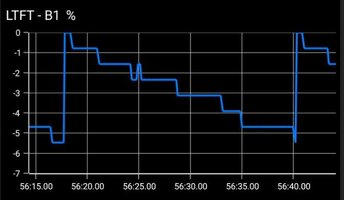
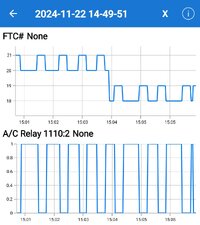
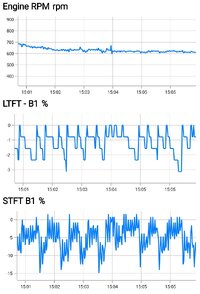
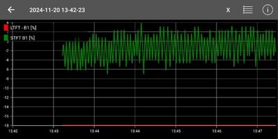
The capture is good and as expected for a hot idle vehicle. Your "observed" LTFT is the problem.... no way it should be sitting in that far negative. In fact, when the STFT swings negative, the sum is almost at coding (-25%)... running too rich.

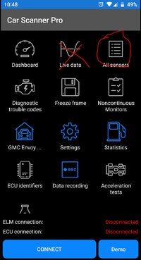
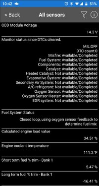
So what could make it idle rich? Is there something to find with my scanner app?

I checked the pressure regulator vacuum line, there's no gas in it, not even the smell. The air filter was changed in march. I put in a stock one.

When I fixed the gas tank, because the cracked/leaking rollover valve had been replaced with a giant hose barb that was still leaking, I checked the charcol canister and it was dry.

I haven't changed the fuel filter yet, could a dirty one cause an issue like this?

Note: Same log as in post #78
Capture.JPG
 
Last edited:

budwich

Member
Jun 16, 2013
2,190
kanata
For a speed density fuel control system, the MAP and intake air temp are the main inputs. My guess would be the MAP. You have shown a trace of the air temp which is somewhat easy to confirm based on "known" outside temperature athough that could be less than good as intake usually comes by a "hot engine component" (ie. rad). The MAP on the other hand would need a vacuum gage to confirm the readings. I think mooseman suggested pulling the map connection while the truck was running to see how it response. I don't recall, but it should stumble and maybe stall.

I think the other area is the throttle position sensor. The reading might indicate that the system is more open than it actually is... meaning less air is being taken in but the system "calculates" that it should be getting more according to the position. How to know... I don't know without actually using a "command function test tool".
 

Sqrly

Original poster
Supporting Donor
Member
Apr 2, 2024
214
Livingston CA
For a speed density fuel control system, the MAP and intake air temp are the main inputs. My guess would be the MAP. You have shown a trace of the air temp which is somewhat easy to confirm based on "known" outside temperature athough that could be less than good as intake usually comes by a "hot engine component" (ie. rad). The MAP on the other hand would need a vacuum gage to confirm the readings. I think mooseman suggested pulling the map connection while the truck was running to see how it response. I don't recall, but it should stumble and maybe stall.

I think the other area is the throttle position sensor. The reading might indicate that the system is more open than it actually is... meaning less air is being taken in but the system "calculates" that it should be getting more according to the position. How to know... I don't know without actually using a "command function test tool".

How would I go about checking the map .... NVM took like 2 seconds to find a video. I don't have a vacuum pump.
 

Sqrly

Original poster
Supporting Donor
Member
Apr 2, 2024
214
Livingston CA
I reread the entire thread.

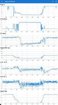
Right after the 2nd TB Relearn (Post #24) when it was idling correctly with the defroster on and the AC compressor turning on and off the LTFT looked like this.

cap1.JPG

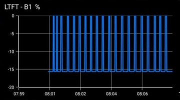
Now it's stalling again and it looks like this.

cap2.JPG

What is happening to make it change?
 

Forum Statistics

Threads
23,686
Posts
642,038
Members
19,152
Latest member
Lihhim

Members Online