ConeKilrAutoX
Member
- Joined
- Dec 8, 2011
- Posts
- 1,179

gmcman said:It needs to go between the TB and the air filter. I would try to locate it closer to the TB. Can you post a pic of the current configuration?
Sparky said:How well is that going to work with positive intake pressure though instead of vacuum?
ConeKilrAutoX said:sure thing. its dark but this is an older pic from a few days ago with my testing intake with MAF sensor and the hose leaving the intake tube goes to the fpr. thanks for the help!

 thank you
  It sounds like some people want this build done almost as much as me haha! waaaa pssssh!
ConeKilrAutoX said:Hi. Thanks for the question and concern I appreciate any suggestions and help. I believe my tune is set atmospheric and the MAF sensor (when the turbo is installed) will pick up higher than atmospheric psi and will inject fuel accordingly based on the tables limquat has set up for me. After a scan I should hopefully have an idea of what is causing the problem.
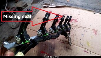
gmcman said:Why is it wet that far from the nozzles? Not sure what type of DMM you have but can you measure the pulse width of the injectors? Can you find out what the tune is calling for?
How limited are the stock injectors for 7-8 PSI of boost?
Just a hunch but it sounds like you need to cut the pulse width way down for these high flow injectors if they are functioning properly.
Is your FPR functioning properly?
bruhaba said:fpr - if you have a return style system, these typically run referenced to manifold pressure, so the vacuum line on the regulator should come straight from the manifold(behind the throttle body). Same whether you run boost or not. As I said earlier, the point is to have the injector seeing the same differential pressure between the rail and the intake all the time. This is how every boosted/non boosted vehicle with a return line has been for me and also how my supercharged 06 is setup now with an AFPR and return line. What kind of system do you have? Did you put in an aftermarket regulator?
ConeKilrAutoX said:Ok. stock fpr with vacuum line connected to a vacuum block distributer that is connected to the intake maniold via the manifold port that was under the stock intake resonator.

bruhaba said:fpr - if you have a return style system, these typically run referenced to manifold pressure, so the vacuum line on the regulator should come straight from the manifold(behind the throttle body). Same whether you run boost or not.
ConeKilrAutoX said:Ok. stock fpr with vacuum line connected to a vacuum block distributer that is connected to the intake maniold via the manifold port that was under the stock intake resonator.
throttle body evap vent is hooked up stock
the crankcase vent hose I have running to an oil catch can
the breather for the crankcase is to the intake pipe post MAF and pre TB.
thanks for the help!
ConeKilrAutoX said:damn sorry I was getting confused I have the catch can installed to the PVC side
View attachment 14664
not the crankcase vent ... sorry about that. the crank case vent I have hooked up to the intake pipe post MAF but pre throttle body.
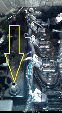
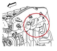
gmcman said:I'm curious as to why the crankcase vent hose wasn't kept in it's stock location? Did you use a different intake without the provision for the tube? I don't know for sure but did all the years have the crankcase vent tube on the left side of the intake?
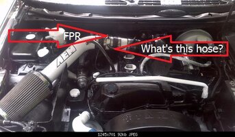
What's the other hose in the pic on the intake? Does this hose require manifold vacuum? gmcman said:OK, all coming together now...
I assume the FPR hose is the FPR?
Reason I'm asking all this is the motor ran in this setup based on the earlier video you posted when you removed the A/C from the belt routing.
limequat said:That's a 1 bar MAP, right?