05 Envoy XL 5.3 Won't Crank

budwich

Member
Jun 16, 2013
2,052
kanata
Could you tell me what wires should be energized at the ignition switch given the key position?
This is from the GM SI dealing with the BCM and the power modes. Beyond this, my pay grade goes to zero... :smile:
 

Attachments

  • bcmpowermode.pdf
    16 KB · Views: 11
Last edited:
  • Like
Reactions: azswiss and mrrsm

EnvoyMan

Original poster
Member
Jan 27, 2023
87
Parkdale
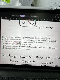
an update, I checked a bunch of fuses I saw on another forum post with similar issues and this is what I found: IMG_1937.jpeg

I did checks 6&7 shown above, and the fuses underlined/checked with green showed power at the appropriate states, but the ones marked with x (engine bay fuses 16,22,28) did not show 12V. The fuses weren’t blown, and the J case fuses (IGN A and B) had 12V at all times.

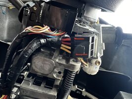
Another observation, which I don’t really know is right or wrong, was that the following wires NOT marked with a red line on the ignition switch had 12V in ACC:
IMG_1935.jpeg

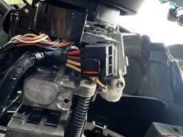
And the following wires NOT marked with red had 12V in RUN:
IMG_1936.jpeg

Let me know what you guys think. I haven’t checked the remaining wires on the upper half of that connector, but lmk if I should and what I should expect. I’m moving on to reading the front splice pack with an oscilloscope. Do you guys know where the rear seat splice pack is for the XL? I can’t find it from the videos I’ve seen so it may be different between the SWB and LWB models.
 

EnvoyMan

Original poster
Member
Jan 27, 2023
87
Parkdale
Guys! I have another update but I’m a bit confused now. I noticed by rear fusebox post bolts were loose, so I went ahead and tightened them up to see if my car would work, but it didn’t. As I was preparing to probe the different class 2 lines on my scope, I took the comb out to see how it works, and I put it back in. I went ahead and then turned the key forward one notch to see that I did have data being read, but then putting it in the run position, I suddenly have all my dash lights again and my PRNDL screen and DIC are back on when they weren’t turning on previously. However, my passlock light is on even though I still have the original PCM in, but that may be because I did swap with the spare I bought when I went to the shop yesterday to see if it made a difference (it wasn’t programmed), which it didn’t. I’m going to do the passlock learn and report back if she’s happy again.
 

EnvoyMan

Original poster
Member
Jan 27, 2023
87
Parkdale
The weird thing is, the passlock light won’t turn off after 11 minutes (I set a stopwatch). After I cycled the key off for 30 seconds and then back to run, the passlock light was gone for several seconds unlike before when it would come on immediately, but it did still come back. I’m going to try this a few more times.
 

EnvoyMan

Original poster
Member
Jan 27, 2023
87
Parkdale
Okay, I misdiagnosed a little. My dash lit up because the comb fell out while I wasn’t looking. My radio, windows and nothing else worked which made sense. As soon as I put the comb back in, my dash reverted to its infamous CEL and battery light only state but my power windows, radio, etc started working. Going to hunt down which data line is bringing me down
 

EnvoyMan

Original poster
Member
Jan 27, 2023
87
Parkdale
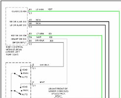
I’ve narrowed it down to the BCM, with fuse 58 (TBC 1) and the connection at fault is within the green ribbon that goes into the BCM, but that may just be because it powers the BCM on. Removing either the fuse or the ribbon causes my instrument cluster and everything else to light up again, but obviously passlock is keeping me from starting it since the pcm and bcm need to see each other. Without the fuse/connector, my power windows, locks, etc don’t work anymore. Referring to the splice 205 pack diagram, it doesn’t matter if pin H (joins SP205 and SP206) is connected or not, connecting pin M (BCM) and only pin M to the rest of the class 2 network screws things up. Connecting in the BCM, however, doesn’t take down the class 2 network. On my scope, I continue to get nice square pulses with a 7.5V peak.

All door locks, remote lock, power window switches (for the driver and individual doors), seat adjustment, and rear quarter glass still work, but without pin H connected to pin M they won’t operate, so the BCM works to an extent. At this point, I am stuck. Is there a way I can single out if it’s the BCM that’s ruined or if there’s anything else I could look at related to the BCM?
 
  • Like
Reactions: movietvet

movietvet

Member
Dec 21, 2022
458
Oregon
I ordered my GM ignition switch from NAPA and had it pretty quick. I still think you either have a defective switch from AZ or is not cammed right. My 2 videos at you tube explain this. This is such a long thread, you may have already replaced with another switch and I did not see it.
 

EnvoyMan

Original poster
Member
Jan 27, 2023
87
Parkdale
I ordered my GM ignition switch from NAPA and had it pretty quick. I still think you either have a defective switch from AZ or is not cammed right. My 2 videos at you tube explain this. This is such a long thread, you may have already replaced with another switch and I did not see it.
I have replaced the switch already. The car’s state changes when I turn my key so I’m positive it is indexed right. Did you see my bit about the BCM?
 
  • Like
Reactions: movietvet

mrrsm

Lifetime VIP Donor
Supporting Donor
Member
Oct 22, 2015
7,748
Tampa Bay Area
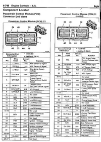
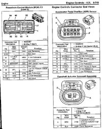
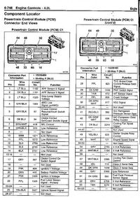
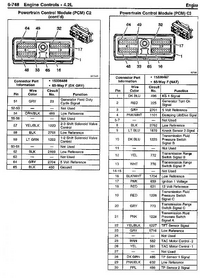
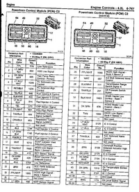
Besides having these PCM Pin-Out Diagrams for Continuity Tracing between the PCM and the BCM, the link to the On Topic Thread may assist you with more information about Diagnosing BCM Issues:


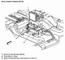
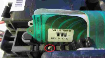
Also... Investigate completely removing (Cleaning and Replacing) the Under Seat Rear Fuse Block and BCM and check for any Debris, Detritus, Liquid Invasion and Broken Wiring at the Harness and Connectors, too:

upload_2017-4-25_20-37-25.pngupload_2017-4-25_20-34-43.pngupload_2017-4-25_20-34-21.pngupload_2017-4-25_20-33-51.png2004trailblazerpcm4-jpg.73337.jpegDUALCALSS2ATHEBCM3.jpgBODYCONTROLMODULE.jpg45145449694_6aa90e05da_c.jpg

This Can of CRC Electrical Circuit Cleaner is indispensable in such situations:


618DEAhKusL._AC_SL1500_.jpg
 
Last edited:
  • Like
Reactions: movietvet

EnvoyMan

Original poster
Member
Jan 27, 2023
87
Parkdale
Besides having these PCM Pin-Out Diagrams for Continuity Tracing between the PCM and the BCM, the link to the On Topic Thread may assist you with more information about Diagnosing BCM Issues:


Also... Investigate completely removing (Cleaning and Replacing) the Under Seat Rear Fuse Block and BCM and check for any Debris, Detritus, Liquid Invasion and Broken Wiring at the Harness and Connectors, too:

View attachment 108896View attachment 108897View attachment 108898View attachment 108899View attachment 108900View attachment 108901View attachment 108902View attachment 108903

This Can of CRC Electrical Circuit Cleaner is indispensable in such situations:


618DEAhKusL._AC_SL1500_.jpg
I do have the electronic cleaner, but I’ve already sprayed the pcm connectors so I’ll go ahead and do the fusebox connections. I also have a 5.3 so my pcm connectors are different. Which pins should I be checking for continuity, for example? Also what am I looking for with the APP and cam position sensor? My CPS also has a different connector since it’s a 5.3.
 
  • Like
Reactions: movietvet

budwich

Member
Jun 16, 2013
2,052
kanata
In all of this, I don't think that I have seen you check fuse 17 although maybe you mentioned it somewhere that the pcm was getting a start signal (12v).
 
  • Like
Reactions: movietvet

EnvoyMan

Original poster
Member
Jan 27, 2023
87
Parkdale
In all of this, I don't think that I have seen you check fuse 17 although maybe you mentioned it somewhere that the pcm was getting a start signal (12v).
That doesn’t sound familiar, what is fuse 17 supposed to be? I do remember getting 12v out of the NSS and constant 12V on the starter relay. I’m definitely not going to get the pcm ground on that relay since the bcm is misbehaving. Do you have any thoughts on fuses 16, 22, and 28 not being energized in ACC?
 
  • Like
Reactions: movietvet

mrrsm

Lifetime VIP Donor
Supporting Donor
Member
Oct 22, 2015
7,748
Tampa Bay Area
Try *Pin Tracing* the Class 2 Network Connections for Continuity (and Powers and Grounds) in between the P10 PCM and the BCM using THIS Bench Top Programming Harness Diagram originally conceived and shared here at GMT nation ...by Bill Reid:

Benchtop P10 Rev0_1.jpg
 
Last edited:
  • Like
Reactions: movietvet

movietvet

Member
Dec 21, 2022
458
Oregon
I have replaced the switch already. The car’s state changes when I turn my key so I’m positive it is indexed right. Did you see my bit about the BCM?
Yes, did you see both of my you tube videos about install and a correction of the install for the teeth being cammed/aligned wrong? It would still start and run but the no crank/no power was intermittent.
 

EnvoyMan

Original poster
Member
Jan 27, 2023
87
Parkdale
Yes, did you see both of my you tube videos about install and a correction of the install for the teeth being cammed/aligned wrong? It would still start and run but the no crank/no power was intermittent.
My car’s dash light behaviors are repeatable if I connect/disconnect the data line for the BCM. I did see your videos but I’m not having the same issues as the ones in the videos. Admittedly, the shop I got this back from did say my switch was one tooth off but I haven’t touched it since. Perks of being in a rush.
 
  • Like
Reactions: movietvet

EnvoyMan

Original poster
Member
Jan 27, 2023
87
Parkdale
Try *Pin Tracing* the Class 2 Network Connections for Continuity in between the P10 PCM and the BCM using THIS Bench Top Programming Harness Diagram originally conceived and shared here at GMT nation ...by Bill Reid:

View attachment 108904
Thank you, I’ll give that a look. How does this translate to the 5.3 though? The connectors aren’t the same on the PCM. Will the pin names match?
 
  • Like
Reactions: movietvet

mrrsm

Lifetime VIP Donor
Supporting Donor
Member
Oct 22, 2015
7,748
Tampa Bay Area
Correct... but if you read through Post #2, Post #38 and Post #40 of THIS Thread... the same concept of a Bench Top Programming Diagram for the P01 LS PCM unfolds in great detail as well. You may have to research the BCM portion just a little further:


More Information for users of LSDroid and Tuner-Pro:


Last edited:

TJBaker57

Member
Aug 16, 2015
2,900
Colorado
This will be a somewhat rushed and limited response and may be not fully fleshed out but there is a point I wish to make here. Today I did an experiment. No big surprise there I do this all the time.

I took one of my spare clusters and connected it to one of my Bluetooth OBD2 adapters and recorded the message traffic as I proceeded. There are NO OTHER modules involved or connected, this is a stand alone cluster right now. I connected the appropriate ground and then the 12 volt always hot power. The cluster cycled as expected, no lights at all but the stepper motors did the expected drop to zero as a reset and there is about 5 seconds of message traffic. One way traffic of course as there are no other modules here.

Next I powered the "hot in RUN and START" line which is the only other power to the cluster. This causes a lot of traffic and lights. Not ALL the lights but a good many. There was a 'click' heard but no gauge zero resets. Some lights go out after a few seconds then later some other lights go out and then the check gauges light comes on. Oh, also the DLC comes on displaying the expected unknown driver message followed by odometer.

In the above state the cluster continues to send its awake status message every 2 seconds all other traffic stopped.

At this point I added a BCM to the test, properly supplying the ground(s) and all of the "hot at all times" BCM powers. There are a handful of them. Within milliseconds all of the remaining lighted items on the cluster went off leaving the cluster dark.

WHY??

Well I'll tell you why. In the data traffic when the cluster was all alone on the network it repeatedly asks what is the current network status (power mode) but there was no BCM to answer so the cluster stayed in what I assume is a default state of awake and operating. The cluster also was seen asking for a VIN number but again there was no-one to answer. But within milliseconds of powering up the BCM broadcast the current power mode. Since there were no ignition switch powers coming to the BCM (key off position) the BCM announced that status. The cluster received that power mode message and complied. It made NO DIFFERENCE that the cluster still had the "HOT in RUN and START" signal still applied as the BCM power mode message takes precedence.

Oscilloscopes are nice tools and can verify the presence of a signal but they cannot tell you what module is sending that signal, who is receiving the message, nor what the message is conveying. Sometimes it can help a great deal.

I need to study your info from today and see what I can see. One thing I noticed is an error in the stated power status for the key in the ACC position. And it may have been my own error there as it looks familiar to me. Fuses 16, 22, and 28 should be powered in RUN but NOT in ACC.

If the BCM is not seeing all the signals it uses to determine key state then it may be possible that the BCM is sending a power mode message that is shutting down modules.
 
  • Like
Reactions: movietvet

TJBaker57

Member
Aug 16, 2015
2,900
Colorado
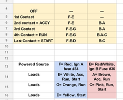
This is what I made and use for reference of a GMT360 Ignition switch. I made this as I disassembled said switch and explored the inner workings along with identifying circuitry using the wiring diagrams.

Screenshot_20230701-192734.png


The top panel showed the results of ohmeter/continuity tests as the switch was rotated. Some contacts were seen to close before others with regards to the location of detents in the switch.

The red and blue panels show the wire colors at the switch, the terminal designations, and the key positions when said wire is powered. Example: Terminal "E" is the white wire and it is powered in ACC, RUN, and START. Looking above you see it is powered from terminal "F" and that is the red wire, OGN A, powered from fuse 34.
 

EnvoyMan

Original poster
Member
Jan 27, 2023
87
Parkdale
This is what I made and use for reference of a GMT360 Ignition switch. I made this as I disassembled said switch and explored the inner workings along with identifying circuitry using the wiring diagrams.

View attachment 108905


The top panel showed the results of ohmeter/continuity tests as the switch was rotated. Some contacts were seen to close before others with regards to the location of detents in the switch.

The red and blue panels show the wire colors at the switch, the terminal designations, and the key positions when said wire is powered. Example: Terminal "E" is the white wire and it is powered in ACC, RUN, and START. Looking above you see it is powered from terminal "F" and that is the red wire, OGN A, powered from fuse 34.
Just to make sure I understand correctly, for the top half in the ACC position, F&E are shorted together, and B&A are shorted together? Furthermore, F&E are sorted at all times? Thanks for putting this together!

It looks like my ignition switch behaviors in terms of powered wires for ACC and RUN are consistent with your spreadsheet, at least for the lower 4 wires.
 
  • Like
Reactions: movietvet

EnvoyMan

Original poster
Member
Jan 27, 2023
87
Parkdale
This will be a somewhat rushed and limited response and may be not fully fleshed out but there is a point I wish to make here. Today I did an experiment. No big surprise there I do this all the time.

I took one of my spare clusters and connected it to one of my Bluetooth OBD2 adapters and recorded the message traffic as I proceeded. There are NO OTHER modules involved or connected, this is a stand alone cluster right now. I connected the appropriate ground and then the 12 volt always hot power. The cluster cycled as expected, no lights at all but the stepper motors did the expected drop to zero as a reset and there is about 5 seconds of message traffic. One way traffic of course as there are no other modules here.

Next I powered the "hot in RUN and START" line which is the only other power to the cluster. This causes a lot of traffic and lights. Not ALL the lights but a good many. There was a 'click' heard but no gauge zero resets. Some lights go out after a few seconds then later some other lights go out and then the check gauges light comes on. Oh, also the DLC comes on displaying the expected unknown driver message followed by odometer.

In the above state the cluster continues to send its awake status message every 2 seconds all other traffic stopped.

At this point I added a BCM to the test, properly supplying the ground(s) and all of the "hot at all times" BCM powers. There are a handful of them. Within milliseconds all of the remaining lighted items on the cluster went off leaving the cluster dark.

WHY??

Well I'll tell you why. In the data traffic when the cluster was all alone on the network it repeatedly asks what is the current network status (power mode) but there was no BCM to answer so the cluster stayed in what I assume is a default state of awake and operating. The cluster also was seen asking for a VIN number but again there was no-one to answer. But within milliseconds of powering up the BCM broadcast the current power mode. Since there were no ignition switch powers coming to the BCM (key off position) the BCM announced that status. The cluster received that power mode message and complied. It made NO DIFFERENCE that the cluster still had the "HOT in RUN and START" signal still applied as the BCM power mode message takes precedence.

Oscilloscopes are nice tools and can verify the presence of a signal but they cannot tell you what module is sending that signal, who is receiving the message, nor what the message is conveying. Sometimes it can help a great deal.

I need to study your info from today and see what I can see. One thing I noticed is an error in the stated power status for the key in the ACC position. And it may have been my own error there as it looks familiar to me. Fuses 16, 22, and 28 should be powered in RUN but NOT in ACC.

If the BCM is not seeing all the signals it uses to determine key state then it may be possible that the BCM is sending a power mode message that is shutting down modules.
For a quickish rundown of stuff that is relevant to this problem, check out posts 69, 73, 82, 86, and 87. 86 and 87 are the most important ones in my opinion.

Since my BCM isn't interrupting my Class 2 line, I think it would be a good idea to get a data readout to see what happens when the BCM joins the party of other modules, since clearly the BCM isn't playing nice with other modules except for the ones dealing with door functions, lights, liftgate, radio, and all windows. My oscilloscope has a logic analyzer and it can read UART, 1Wire, and CAN among others, but I'm not sure which would work best with Class 2. Would that be sufficient? Without the BCM in the Class 2 network, none of those above things function and the radio doesn't turn on (which from an early post I believe you made in this thread it makes sense).

I'll recheck fuses 16, 22, and 28 in RUN, I must have misread.

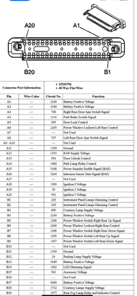
Your second set of paragraphs is pretty eye opening and very informative. So if the BCM doesn't see all the expected ignition powers, it'll think the car is shut off and it'll shut down other modules even if my key is in ACC/RUN? Are these key states determined by pins A18-A20 on the ribbon connector for the BCM:
1688263915999.png
 
  • Like
Reactions: movietvet

TJBaker57

Member
Aug 16, 2015
2,900
Colorado
Just to make sure I understand correctly, for the top half in the ACC position, F&E are shorted together, and B&A are shorted together?

That is correct.

In another sheet I tried to list the various circuits that are powered by each of the ignition switch wires. There were some issues with having variations like a 5.3 vs a 4.2 and other such ciruit differences.

Ithink you posted a video maybe of your BCM tests? I will have a look there next. That ribbon cable is mission critical as it carries most (maybe all?) of the ignition switch signals to the BCM.
 
  • Like
Reactions: EnvoyMan

EnvoyMan

Original poster
Member
Jan 27, 2023
87
Parkdale
That is correct.

In another sheet I tried to list the various circuits that are powered by each of the ignition switch wires. There were some issues with having variations like a 5.3 vs a 4.2 and other such ciruit differences.

Ithink you posted a video maybe of your BCM tests? I will have a look there next. That ribbon cable is mission critical as it carries most (maybe all?) of the ignition switch signals to the BCM.
Yes, in post 86 I posted a short test video showing how adding in the BCM screws everything up, and disconnecting it lets the IPC power on and show me more dash lights and the fuel gauge readout. I later progressively added all the other modules on the splice pack in one by one minus the BCM and everything was still behaving as expected. My HVAC panel even started working and my airbag systems were online. No radio though, only the chimes were active without the BCM. Here's a video of that: https://photos.app.goo.gl/9fGK9PNg5Jm9YPpp6

The BCM being present in the class 2 network always kills power to the IPC and HVAC, regardless of whether pin H (connection for the rear splice pack to the front splice pack) is present in the network or not. Therefore I don't believe any of the modules from the rear splice pack are causing this, which I honestly was hoping to be the case.

About the ribbon, disconnecting it let the IPC and HVAC work again, but it seems to provide power to the BCM so it probably just went offline.

Edited for clarity.
 
Last edited:

TJBaker57

Member
Aug 16, 2015
2,900
Colorado
I'll recheck fuses 16, 22, and 28 in RUN, I must have misread.

I may have erred when I posted that data as well.


My oscilloscope has a logic analyzer and it can read UART, 1Wire, and CAN among others, but I'm not sure which would work best with Class 2


The Class 2 message protocol in use here is SAE J1850 VPW. I don't actually know much about oscilloscopes so I cannot say if any can decode this J1850 data stream.

Your MX+ can do it but I have zero iPhone knowledge so cannot advise there. You would need 2 things to work there. First the iPhone needs to allow an app to connect to the MX+ as a serial device and secondly you would need a serial terminal app that will work with that MX+ and allow you to record a logfile.

The serial terminal does not need to be anything automotive specific or the like, all that is needed is a 'dumb' terminal that will record a text logfile. Timestamps are nice but not essential.


Are these key states determined by pins A18-A20 on the ribbon connector for the BCM:

Yes, that is at least some of them. Also the Accesory Voltage at B15 comes from the ign switch. Also there are several "hot all the time" 12 volt signals that should be there. I cannot say with certainty that these latter supplies are strictly essential but I would want them there.
 

EnvoyMan

Original poster
Member
Jan 27, 2023
87
Parkdale
I may have erred when I posted that data as well.


The Class 2 message protocol in use here is SAE J1850 VPW. I don't actually know much about oscilloscopes so I cannot say if any can decode this J1850 data stream.

Your MX+ can do it but I have zero iPhone knowledge so cannot advise there. You would need 2 things to work there. First the iPhone needs to allow an app to connect to the MX+ as a serial device and secondly you would need a serial terminal app that will work with that MX+ and allow you to record a logfile.

The serial terminal does not need to be anything automotive specific or the like, all that is needed is a 'dumb' terminal that will record a text logfile. Timestamps are nice but not essential.


Yes, that is at least some of them. Also the Accesory Voltage at B15 comes from the ign switch. Also there are several "hot all the time" 12 volt signals that should be there. I cannot say with certainty that these latter supplies are strictly essential but I would want them there.
UART is related to serial data. I will do some research to see if I can have my iPhone see the MX+ as a serial device. What would be your preferred Android app to do this? My aftermarket radio is an android radio which came with the Torque app preinstalled so I may be able to load your app and connect to my OBDLink MX+ through there if I can still use BT to get serial data.
 

TJBaker57

Member
Aug 16, 2015
2,900
Colorado
What would be your preferred Android app to do this?

Hands down I recommend Serial Bluetooth Terminal by Kai Morich.


I remember that recent versions of the Torque Pro App added a terminal feature with 2 variants but I don't think it offered logging abilities therein. The logging is essential. But nonetheless the addition of a terminal mode in Torque Pro is a great addition for advanced users.
 

TJBaker57

Member
Aug 16, 2015
2,900
Colorado
What would be your preferred Android app to do this

As an addendum in case the terminal app works on your android radio...

You may need to adjust some app settings for things like end of line characters, buffer size and so on. But to get started pair the MX+, select the MX+ in "devices", the app will try to connect to the MX+, once connected you should see an "OK". Enter the following at the prompts pressing return/enter after each entry. (don't type the content in parenthesis)

ATTP2 (try protocol 2)
ATH1 (display message headers)
ATS1 (display a space between each byte)
ATAL (allow long messages)
ATMA (monitor all)

If everything works you will see all message traffic on the class 2 serial data bus. It will be scrolling fast. If it works we can proceed from there.

edit: the above instructions are for ELM based devices or clones. I read that the MX+ has additional slightly different command set but also read they are mostly backward compatible units so it may work just as shown above. Or weay need modifications if any of the above "AT commands" fail.
 
  • Like
Reactions: movietvet

EnvoyMan

Original poster
Member
Jan 27, 2023
87
Parkdale
As an addendum in case the terminal app works on your android radio...

You may need to adjust some app settings for things like end of line characters, buffer size and so on. But to get started pair the MX+, select the MX+ in "devices", the app will try to connect to the MX+, once connected you should see an "OK". Enter the following at the prompts pressing return/enter after each entry. (don't type the content in parenthesis)

ATTP2 (try protocol 2)
ATH1 (display message headers)
ATS1 (display a space between each byte)
ATAL (allow long messages)
ATMA (monitor all)

If everything works you will see all message traffic on the class 2 serial data bus. It will be scrolling fast. If it works we can proceed from there.

edit: the above instructions are for ELM based devices or clones. I read that the MX+ has additional slightly different command set but also read they are mostly backward compatible units so it may work just as shown above. Or weay need modifications if any of the above "AT commands" fail.
Great, I'll give that a shot tomorrow. If the radio doesn't work, I'll go buy a cheap android tablet off Marketplace or Walmart and use that. Anything else I should test while I'm there? For example, if you knew what pins the BCM gets its power states from the key position I could backprobe them to see if I get the right voltages.
 

mrrsm

Lifetime VIP Donor
Supporting Donor
Member
Oct 22, 2015
7,748
Tampa Bay Area
More excellent "Grist for The Serial Data Mill " from @TJBaker57 :

 
  • Like
Reactions: movietvet

EnvoyMan

Original poster
Member
Jan 27, 2023
87
Parkdale
@TJBaker57 another thing I wanted to mention, which I’m not sure is obvious from the video, but when the BCM is connected to the network while my key is already in the run position and the cluster lights and HVAC panels are okay, it takes a power cycle from the key to make the issue I was having come up again. That is, my cluster will then only light the battery light and CEL light, no HVAC panel. When the BCM is disconnected while my key is already in run, the instrument panel lights up a few seconds after and my restraint lights flash, and the fuel gauge turns on. NO voltmeter comes on though. This’ll continue to work through power cycles as long as the BCM is not connected again. Lmk if that makes sense.
 
  • Like
Reactions: movietvet

EnvoyMan

Original poster
Member
Jan 27, 2023
87
Parkdale
Did some wire diagram tracing and made a few observations. For one, the TBC 1 fuse supplies battery power to the BCM to one of the plugs, not the ribbon. Removing other fuses that provide battery power to the BCM has no effect, but removing this shuts down the BCM (no door locks, windows, accessories). It also lets my IPC (including the fuel gauge) and HVAC panel work again, but my car won't crank since no BCM-PCM comms. Does anyone know if this is the main power to the BCM?

That leaves me asking: why does removing the ribbon cable have the same effect as removing TBC 1, even though those two aren't related? I removed all TBC fuses yesterday that send power through the ribbon to no change in the bad behavior, so at the very least they aren't mission critical power sources, but the ribbon DOES contain various signals such as the Class 2 wire that goes into splice pack SP205 (the pack I messed with yesterday). Since the Class 2 network isn't being brought down, I think it is working as it should, relaying what the BCM is telling everyone else. It ALSO contains IGN 0, 1, and 3 voltage, which are from fuses 50 (rear block), 16 (front block), and 52 (rear block) respectively. I confirmed all those have power except 16, which I didn't correctly test yesterday but I will get to it today. So that leaves me a bit lost, as I thought one of those sources would be down, causing the BCM to incorrectly determine the power mode. I will still check to see if the ribbon is getting the appropriate power and signals, but I have a feeling I'm going to be disappointed.
 
  • Like
Reactions: movietvet

EnvoyMan

Original poster
Member
Jan 27, 2023
87
Parkdale
My data shows the the Class II signal on Connector 1, pin B1, not the ribbon cable.
You are right. My bad. I think my best move at this point would be to dump the class 2 network traffic and see what's going on rather than chasing different powers. Would it be a good idea to get a dump with JUST the BCM connected and another with the rest of the network connected?
 
  • Like
Reactions: movietvet

EnvoyMan

Original poster
Member
Jan 27, 2023
87
Parkdale
Best to see all traffic.

Assuming we can get that working we could then record certain events, like what is happening when you connect the BCM and the cluster and HVAC drop out.
That's the thing though, connecting the BCM doesn't cause them to drop out until after I power cycle the key. On the other hand, disconnecting the BCM while the key is in run and the cluster and HVAC are dropped out causes them to come back on after a few seconds.
 
  • Like
Reactions: movietvet

EnvoyMan

Original poster
Member
Jan 27, 2023
87
Parkdale
This interests me. I am unfamiliar with the "theft deterrent module" as my 2002 apparently does not have such a module. It makes me wonder just what does it do and how does it do it.
I think his scan tool has some limitations, since his $6k scan tool told him that he couldn't even communicate with the BCM when it is almost certainly talking in the Class 2 line. The 2006 wiring diagrams mentioned theft deterrent systems, so I'm guessing my 2005 does too as they are very similar vehicles electrically.
 
  • Like
Reactions: movietvet

Forum Statistics

Threads
23,336
Posts
638,058
Members
18,541
Latest member
33chevyrod

Members Online