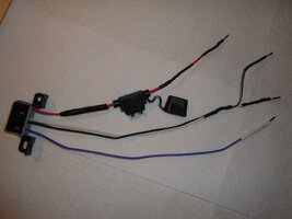
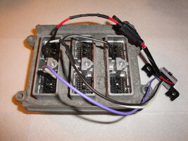
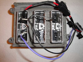
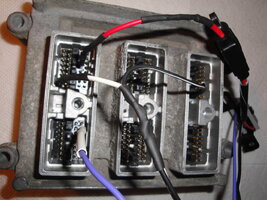
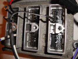
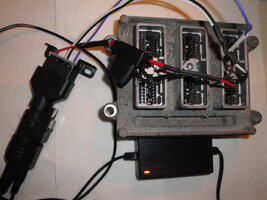
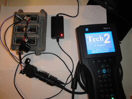
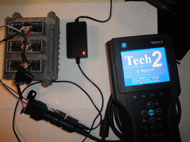
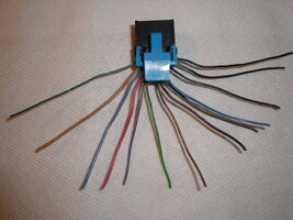
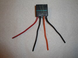
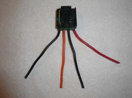
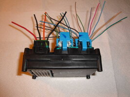
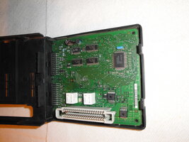
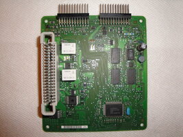
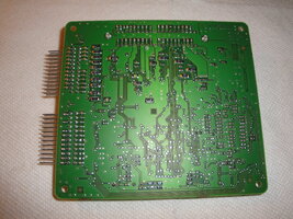
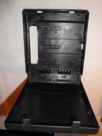
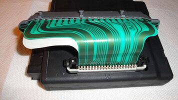
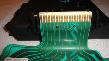
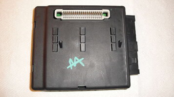
SOLVED! How to Make A "GYMKO" Tech 2 Bench-Top Test Harness

mrrsm

Original poster
Lifetime VIP Donor
Supporting Donor
Member
Oct 22, 2015
8,202
Tampa Bay Area
BIGGER EDIT: 04/24/2019

For THE BEST On Topic Solution ...Go Directly to Post # 42...


BIG EDIT:

This Thread originally was to cover creating a Test Harness to use exclusively for diagnosing and repairing the GM Trailblazer and Envoy, etc Instrument Panel Cluster and Components... but eventually it achieved a life of its own for Testing and Repairing ANY of the Many GM Modules... as long as they are added properly to the "GYMKO" Bench-Top Harness via the precise mirrored PCM and Harness Pin-Outs. More work needs to be done to take each of these ... The BCM, The TCM, The LGM...etc.... one at a time...and document each and every one of the "Most Likely To Fail" among all of the 'Myriad Modules' residing on the Class 2 Databus.

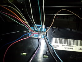
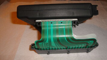
This is an interesting Instrument Panel Cluster Rebuild-Repair Job involving a Professional Re-Fitter of Instrument Clusters receiving essentially a Bag of FUBARed Cluster Components from one of his embarrassed Customers and then essentially performing an UN-FUBAR job and an R&R of misplaced, missing or damaged Stepper Motors. This kind of video is nothing new to those who have had to perform this repair. But what is particularly interesting is the way the E-Tech uses his "GYMKO" Tech2 Scanner to run Bench Top Post Diagnostics to show whether or not his work was successful.

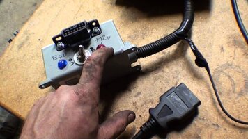
What is Cool also about this video is that this Dude sort of "lifts his skirts" a little to show a separate Homemade Diagnostic Harness that includes the OEM Vehicle Cluster Connector AND a separate OBD2 DLC Connector mated up with some sort of a Half-Assed Wire Breadboard job to allow the use of his "GYMKO" Tech2 to run some neat Bench Tests. I have not looked over any of his other videos to see if he describes how he built this Instrument Cluster-To-Tech2 Powered Test Harness... but it sure would be nice to have one of these for doing these kinds of repairs.

I cannot say that I would blame him for sitting on the secret... as he would be shooting himself in the foot business-wise if the rest of us "GYMKO" Owners knew how he did it. If we have any Members with the 'E-Circuit Savvy' to watch his videos and sort of dope out his Wire Harness connections and choices... perhaps we can reverse engineer it here and then be able to buy the inexpensive OEM IC & OBD2 Connectors and make our own versions of it. Nonetheless... Even if you just did the solder repairs and then plugged it right back into the Truck Harness Cluster Connector... you could power up the Cluster in the Truck B4 completely re-assembling it inside of the Cluster Case... and use Your Own "GYMKO" Scanner to run those very same tests after fixing the Dial Gauges and know for certain...all works well. This would be a very cool thing to be able to do! Many Thanks to the VOP for showing us yet another way to use our "GYMKO" Hand Held Scanner(s). :>)


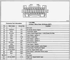
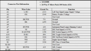
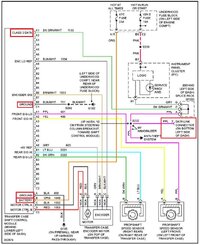
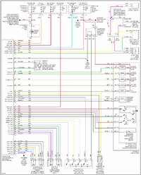
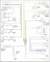
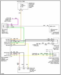
This Attached Image is for the 2004 Instrument Cluster Wiring Schematic for future reference during soldering repairs... (Click on the Image to Enlarge it):
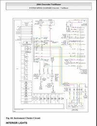
2004 trailblazer instrument cluster wiringcolor.jpg
 
Last edited:

mrrsm

Original poster
Lifetime VIP Donor
Supporting Donor
Member
Oct 22, 2015
8,202
Tampa Bay Area
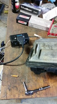
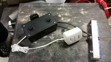
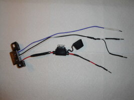
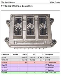
While this idea of running Diagnostics on the Instrument Cluster using the Electrical Harness Connector is just too good to pass up… it seems that something similar could be Doped Out for the One, Two or any Necessary Combination of All Three P10 Style Connectors on the GM 4.2L PCM … and this following set up shows great promise that this could be accomplished if the proper Three Connector Pin-Outs and Power Connections can be translated over to this OBD2 Port Harness Connector as shown in this layout. If sorted out correctly… this same kind of Bench Harness for the GM Tech2 (GYMKO) Hand Scanner for the Bench Top examination and Re-Flashing of the LL8 PCMs should function nicely as a “GYMKO” Tech2 Interface ...IF… Only The Four Wire and Power Supply Connections covered below are the Barest Necessities Required to Make It Work:

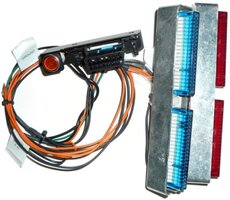
This is a “How To Build” of a Generic GM LS Style PCM-To-OBD2 Bench Top Test-FLASH Harness as listed at the below link.

Disclaimer:

For my own understanding… It was necessary to edit the writing and expressions (but not the content) of this material over to a common standard for describing all of these components and their connections, as I found the original writing very difficult at times to decipher. I make no Claim to being the Originator of these Ideas, Designs or the attached Images and all First Person References that follow in the text pertain strictly to those of The Original Author and Creator of All This Material.

If you prefer reading the Author’s original text... it can be found here:

https://sites.google.com/site/sloppywiki/tuning-information/obd2-bench-harness

Sloppy Mechanics Bench Flashing harness build sheet and instructions for obd2 (blue red/green) style LS ecu's (and some more)”

Components:
1. 12-19 VDC Power Supply, 1amp min ( I have used 500ma, but would recommend staying above One Amp

a. These are very easy to find in old hardware, chargers, external computer components like hard drive enclosures and modem power supplies etc.
b. I have tested 12-19 volts without a problem, that being said, I would stay closer to 12-14 VDC as this is Voltage Levels that most cars use.

2. GM Blue ECU/ECM/PCM(80 Pin Connector)

a. This Connector directly interfaces the ECU.
b. The Connector is usually held in place with a 7mm Bolt to prevent Accidental Disconnection during FLASH and avoiding Unplugging and Bricking anything.

3. In-Cab OBD2 Connector

a. These can be found in JY inside GM Blazers and Cavaliers and so are already Pinned for GM ECMs.
b. Make certain it has Orange, Black and Purple Wires. If so… The rest is EZ.

Component Assembly:

1. On the Power Supply, strip the wires and test them with a Volt Meter to ensure that it works.

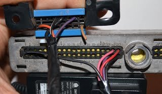
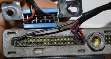
2. You’ll have to flip the connector’s wire side towards you. On the BlueECU Connector wherePin 1 is located in the upper left corner, Pin 20 is located at the Far End of that same Row. Pins 41-60 are likewise located on the Bottom Row. Only 4 Pins are necessary for this to function … the rest can remain in there, or they can be de-pinned to clean everything up.

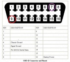
3. Position the OBD2 Port Connector, with the Wider Side Facing Up and the wire contact points facing you displayed as Pins 1-8 situated at the top, and Pins9-16 located at the Bottom. You are only using 4 wires on this Connector…with the others mentioned below dedicated to the 12 VDC issues.

4. Take the Positive Power Wire from the Power Supply, and connect it to Pins 19 and 20 on the Blue ECU Connector, (in the Upper Right Two Pins) and then connect it to the OBD2 Portat Pin 9 (Located at Bottom Left).

5. Then take the Ground Wire and connect it from the Pin 1 (upper left) on the Blue ECU Connector over to Pins4 and 5, (upper middle) on the OBD2 Port Connector.

6. Then take the Purple Serial Data Wire and connect it from Pin 58 on the Blue ECU Connector(lower right side) over to the OBD2 Port Connector Pin 7 (upper right side)

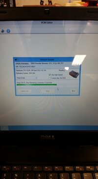
Now before doing anything else, Plug it in and see if you can access the ECU with whatever you are using on the OBD2 Side. Ifyou can Connect/Read/Write,then You Are Set.


In Brief… USING JUST THE FOUR WIRES and the POWER SUPPLY CONNECTIONS:

Connect the 12VDC (+) Power Wire over to OBD2 Port Pin 9 (Orange) and to Blue ECU Pins 19 and 20 (Pink/Red)
Connect the Ground (-) Wire from the OBD2 Port Pins 4-5 over to Blue ECU Pin 1
Connect OBD2 Port Pin7 (Purple) over to Blue ECU Pin 58 (Serial Data Line)

Done!

Note:
As shown in the Image…Pin 60 does NOT need to be used (It was attached during testing and just left it in there). The same applies to Pin 16 (Brown Wire on the OBD2 Port) ...as it was clipped off during the JY Claim and it was just never de-pinned.
 

Attachments

  • 13124573_10154201566269588_3997395948406816225_n.jpg
    13124573_10154201566269588_3997395948406816225_n.jpg
    134.4 KB · Views: 50
  • 13174173_10154201566214588_94650853115629874_n.jpg
    13174173_10154201566214588_94650853115629874_n.jpg
    139.8 KB · Views: 46
  • 14507217_0.jpg
    14507217_0.jpg
    287.7 KB · Views: 46
  • images.duckduckgo.com.jpeg
    images.duckduckgo.com.jpeg
    182.5 KB · Views: 47
  • number2.JPG
    number2.JPG
    14.8 KB · Views: 55
  • OBD2PINOUTS4HARNESS.jpeg
    OBD2PINOUTS4HARNESS.jpeg
    57 KB · Views: 63
  • 13173822_10154201566364588_8367075051893275183_n.jpg
    13173822_10154201566364588_8367075051893275183_n.jpg
    74.4 KB · Views: 54
  • number1.JPG
    number1.JPG
    386.8 KB · Views: 43
  • number 3.JPG
    number 3.JPG
    23.3 KB · Views: 41

mrrsm

Original poster
Lifetime VIP Donor
Supporting Donor
Member
Oct 22, 2015
8,202
Tampa Bay Area
This is a bit of a H/J of my own thread... But I want to eventually try to make contact with this VOP and see if he will spring for a Free Wiring Diagram of his Home Made "GYMKO" to OBD2 to Instrument Cluster Harness Wiring and Component Schematic and since his Skill Set is something that we value very highly over here at GMTN... It might be nice if some of our folks paid a visit to his Youtube Channel and Joined if possible so he can bounce over 1,000 people and keep his monetization level now that Youtube has stricter rules in playing in their ball park.

Just take this FUBARed Instrument Cluster Repair he is doing in this next video for example. This Guy is performing Damaged and Missing Copper Pad Ray-Trace Jumper Wire Surgery with ultra-thin wire and fine solder to resurrect an absolutely DOA Cluster Logic Board. Not only does he show how this can be accomplished... but he takes the time to display ultra-close up work that will save his customer a Ton of Money since other repair shops had told the customer "No Way...". I seriously doubt there is anyone at GMTN who has not experienced some kind of Instrument Cluster failure over the years... so having the chance to be shown how this gets done at an Atomic level... is a pretty good reason to want to join his Channel. This video is an Education in and of itself with how fine grained his instructions and demonstrated techniques are... with yet another "Guest Appearance" of his "GYMKO" Tech2 Hand Held Scanner to show that once finished ...The Proof of his Work really is in The Solder Pudding:

 
Last edited:
mrrsm

Original poster
Lifetime VIP Donor
Supporting Donor
Member
Oct 22, 2015
8,202
Tampa Bay Area
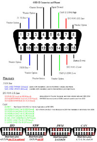
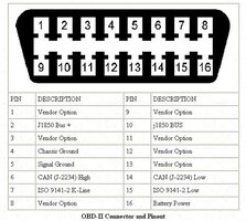
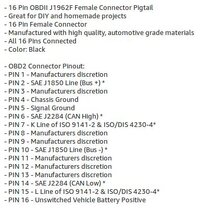
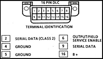
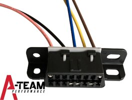
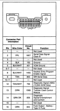
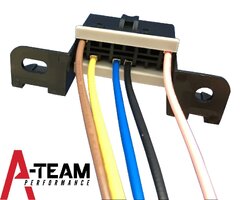
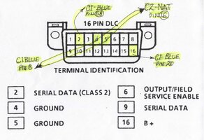
I'm still very curious about how the VOP managed to get the GM Instrument Cluster 24 Wire Delco Connector... feeding data through a common Female DLC Port so the "GYMKO" Tech2 Hand Held Scanner can communicate well enough to command individual Sweep Hand Dials and run other specific Cluster Panel Diagnostics. To that end... I have researched the information that shows the graphic and textual images and Pin-Outs Diagrams for the Delco 24 Pin Instrument Cluster Connector...and the OEM Common Female DLC Port Interface with Wire and Pin Layouts as well. All that remains is for someone very astute to figure out "Which Wires Go Where... What They Do When They Get Attached... And Why...", See the attached images for all the graphic details:

NOTE:

A while back... I picked up a Used GM 4.2L LL8 PCM that included the C1,C2 and C3 Connectors. Upon arrival... I noticed that these Item(s) were sooted up pretty bad and smelled like Burnt Pine Logs... so I am guessing that this device came out of a vehicle that was abandoned in a Forest Fire somewhere and this would explain why the whole apparatus only cost me $20.00 with Free S&H. THIS PCM will be my "Guinea Pig" for Testing this GM PCM P-10-C1,C2,C3 Connector(s)-to-OBD2 Female Port Connector Harness so I can use the 12 VDC Power feeding into the DLC Connector from the "GYMKO" Tech2 Scanner's Power Supply to wake the damned thing up and determine if this arrangement allows them both to enjoy Bi-Directional Communication. If this Harness works and the "GYMKO" Bench Test of a PCM idea pans out... I'll Document the Components, the Wiring and the Assembly Procedures and take some images of the "GYMKO" Blue Screen Reads of it performing... and perhaps even shoot a video of it in action. I've ordered all of the Connectors and a Complete AWG Quality Set of Color Coded Automotive All Copper Wiring to use for this Harness Build... Nothing Ventured... Nothing Gained... Right? :>)
 

Attachments

  • OBD2USB.jpeg
    OBD2USB.jpeg
    203.6 KB · Views: 82
  • OBD2PORTCONNECTORPINOUTS.jpeg
    OBD2PORTCONNECTORPINOUTS.jpeg
    44.3 KB · Views: 70
  • OBD2FEMALEPINOUTS.jpg
    OBD2FEMALEPINOUTS.jpg
    34.3 KB · Views: 68
  • GMDLC16PINSERIALDATAPINOUTS.jpg
    GMDLC16PINSERIALDATAPINOUTS.jpg
    65 KB · Views: 62
  • DLCWIREDPORT.jpeg
    DLCWIREDPORT.jpeg
    29.8 KB · Views: 50
  • DELCOINSTRCLUSTRPINOUTWIRES.jpg
    DELCOINSTRCLUSTRPINOUTWIRES.jpg
    116.8 KB · Views: 59
  • DELCOINSTRCLUSTRPINOUTS.jpg
    DELCOINSTRCLUSTRPINOUTS.jpg
    32.5 KB · Views: 76
  • DELCO24WIRECONNECTORPINOUTS2.png
    DELCO24WIRECONNECTORPINOUTS2.png
    208 KB · Views: 84
  • DELCO24WIRECONNECTORPINOUTS.png
    DELCO24WIRECONNECTORPINOUTS.png
    444.3 KB · Views: 65
  • 61djYCsj0oL._SL1441_.jpg
    61djYCsj0oL._SL1441_.jpg
    110.1 KB · Views: 51
  • IPC_CON_21_1024x1024.jpg
    IPC_CON_21_1024x1024.jpg
    58.7 KB · Views: 52
  • GM16PINDLC.jpg
    GM16PINDLC.jpg
    64.8 KB · Views: 55
  • 61Ucj-rHSML._SL1392_.jpg
    61Ucj-rHSML._SL1392_.jpg
    118.1 KB · Views: 48

mrrsm

Original poster
Lifetime VIP Donor
Supporting Donor
Member
Oct 22, 2015
8,202
Tampa Bay Area
If you have a “GYMKO” Tech2 or a Laptop equipped with a USB to OBD2 Cable and whatever flavor of Scanning-Programming you favor … For you folks who own GM Vehicles equipped with either the GEN III or GEN IV V8 Engines instead of the GM 4.2L LL8 I-6… some of this harness equipment can allow you to fairly easily do 12 VDC powered PCM Bench Diagnostics and Custom Bench Top PCM FLASHING with some well explained and easy to understand designs created to work with the “411” Style PCMs with BLUE and RED 80 Pin Connectors.

Now… If I can only figure out how to do this for the GM 4.2L LL8 PCMs via their P10 Style C1, C2 & C3 Connectors:

https://www.lsenginediy.com/tuning-software-equipment/
http://www.gmtruckcentral.com/articles/2014/Bench-harness/bench-harness.html
http://www.gmtruckcentral.com/articles/12200411.html

Custom LSX Bench Tester Wire Harness Builds:

http://www.superchevy.com/how-to/engines-drivetrain/1401-custom-lsx-wiring-harness-build/

THIS is how expensive these things can get when somebody else having the parts, the knowledge and the wiring schematic… puts these parts together… Just like THAT and sells these for a small fortune:

https://vcmstore.com.au/products/ls1-bench-programming-harness

And likewise… from PAINLESS has a similar device ...for somewhat less money:

https://autoplicity.com/92171-painl..._medium=CSE&utm_campaign=ShoppingComNOFITMENT

And from another GM Forum… another HOW-TO on the work the same project with some variations on the build and with an Excellent Wire to Component(s) Builder Schematic for reference:

https://www.gmforum.com/tuner-139/making-offboard-tuning-278839/

Oh… and for the sake of a little entertainment… Here is an interesting Youtube Video of a “Poor Man’s GM LS Engine Rebuild Break-In Stand” with some surprising and clever ideas displayed on manipulating only “Two Wires” on the OEM Factory Engine Harness to get it to work! The Very Cool VOP (Video Original Poster) Strongly urges Caution and Care while doing this as there is some very obvious danger involved while working with this set up… So Beware the The Ill-Informed about what unrestrained “Engine Torque” is really capable of for those with no Common Sense about Safety:

 
  • Like
Reactions: notevenbro

mrrsm

Original poster
Lifetime VIP Donor
Supporting Donor
Member
Oct 22, 2015
8,202
Tampa Bay Area
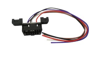
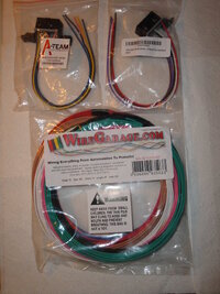
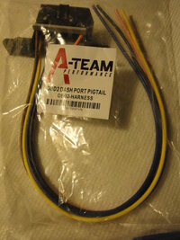
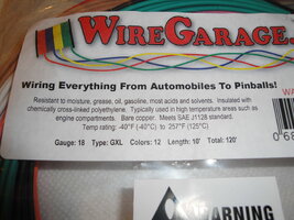
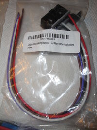
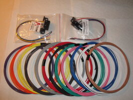
The two OBD2 Port-with-Wire-Connectors and The WireGarage.com Kit containing 120 Feet of AWG (American Wire Gauge) 18 Full Copper Automotive Wire Bundle made up of (12) 10 Foot Length Segments and with (12) Unique Colors that I ordered a few days ago arrived this evening from Amazon. As with everything else that I work on... I hate leaving anything to chance where using the right materials in the proper application is concerned. Using Quality Products along with clear thinking and a decent skill-set are the only ways to work on such projects.

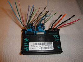
If you intend on modifying or repairing ANY under-hood or critical wiring either on your engines (and components)... or inside of your vehicles... THIS is the stuff you will want to work with and avoid easily overheating sub-standard wiring and inviting fire hazards. I took a few images of these items that will soon find a home in a harness that will solve the inter-connectivity problems of bi-directional communication between my "GYMKO" Tech2 Scanner ..and the GM 4.2L P-10 Style PCM via the C1,C2 & C3 Connectors in a Bench-Top setting. All that remains now is to dope out a proper Wiring Schematic and carefully assemble and test out this "The GYMKO PCM Bench Harness":

DSC01269.jpgDSC01271.jpgDSC01270.jpgDSC01272.jpgDSC01274.jpg
 
Last edited:
mrrsm

Original poster
Lifetime VIP Donor
Supporting Donor
Member
Oct 22, 2015
8,202
Tampa Bay Area
Last edited:
mrrsm

Original poster
Lifetime VIP Donor
Supporting Donor
Member
Oct 22, 2015
8,202
Tampa Bay Area
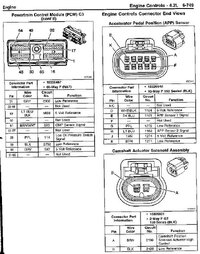
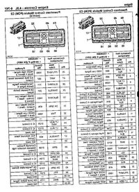
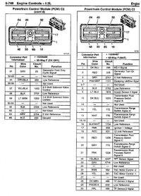
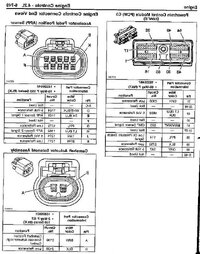
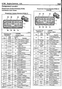
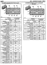
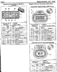
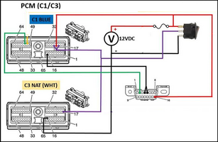
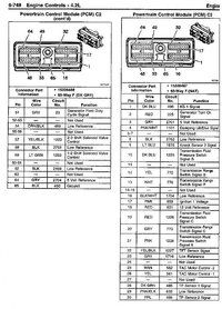
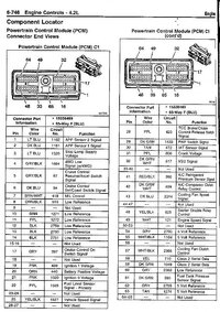
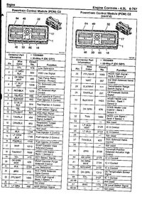
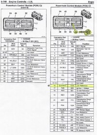
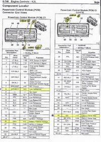
Okay... I just got finished Mapping out the Wire Connections between The GM 4.2L P-10 Style PCM using ONLY Connectors C1 Blue and C3 NAT to make all of the necessary Tie Ins. Connector C3 (GRAY) is NOT employed in this Harness. I marked these wire connection positions on the PCM Connector Print Outs and Highlighted them in Yellow Marker for others to use. The notations over the involved Pins showing the locations of each Individual Pin being selected from within the Pin Matrix using a with a line ending as a Tiny Black Dot resting directly over them and then writing out the information about each of the corresponding connections made between each Connector and The 16 Pin OBD2 (female) PORT out in the Margins of each page.

I've been up all night working on this ... so it might take me a day or so to mock up all of the Hardware Connectors and related Mapped Wiring to create a durable and useful GYMKO Bench Harness... but there is certainly nothing preventing anyone else possessing these Connectors and the proper AWG Wire Segments from making their own version of the Harness from the attached set of images.

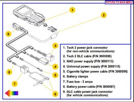
If this comes to pass... and the User has a "GYMKO" Hand Held Scanner... as long as the Tech2 AC/DC Power Supply is Fed Into the VCI-OBD2 Tech2 Cable Adapter right at the Power Connection point where the OBD2 Male component plugs into the Female OBD2 Harness Connector... rather than via the Power Connection Port Located on the Bottom Right Hand Side of The "GYMKO" Tech2 Scanner... then there should ample and sufficient 12 VDC present to Power UP the GM 4.2L P-10 PCM ...AND ALSO.... Power up the "GYMKO" Scanner as well... and then it should NOT be necessary to use an External 12 VDC Power Supply to wake up the PCM during the Diagnostic Procedures and Keep It Running. I emphasize that if the 12 VDC Power Plug is directed instead through the bottom of the "GYMKO" Hand Held Scanner... then this procedure WILL NOT WORK. It follows that if you are using any other type of Scanner or Laptop... Then the GYMKO Harness will need to be re-worked to include the necessary FUSED (+) Positive and (-) Negative Power Lead Connections and unfortunately... at the moment... the attached Diagrams DO NOT INCLUDE THOSE MAPPED POWER CONNECTIONS:

TECH2POWERMETHODS.jpg


C2WHITETOOBD2.jpgC1BLUETOOBD2.jpgBESTGM42LPCMTOOBD2PINOUTS.jpgOBD2TOC1BLUEANDC2NAT.jpg
 
Last edited:
mrrsm

Original poster
Lifetime VIP Donor
Supporting Donor
Member
Oct 22, 2015
8,202
Tampa Bay Area
Okay... This is a Perfect Point to Pause in this Thread for a Better Clarification... It is NOT Absolutely Necessary to have the C1, C2 & C3 PCM Electrical Connectors to Make This Set-Up Work! You would simply have to Create Individual Pin Connectors that need to be carefully Soldered onto the proper contact ends of the GYMKO Bench Test Wiring from Harness leading from The OBD2-Female Port Wires over to the PCM. Of course, each Wire Contact would require a Taped On Set of Simple Instructions as to Which of the Three PCM Pin Matrix (BLUE,GRAY or NAT (TAN) gets these wires attached firmly... by Carefully plugging them in... one at a time so as not to damage the Pins receptacles inside of the PCM. (I can't tell you at this very moment whether or not these Individual Connectors would have to be either Male or Female... as I don't happen to have the three of them removed from the "Guinea Pig PCM" ...Yet... But... please read on for more details).

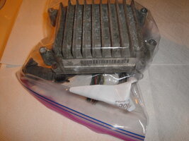
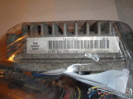
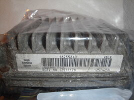
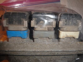
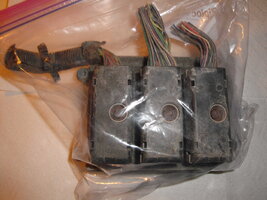
This morning... I brought out the Used and Well-Worn Donor GM 4.2L PCM ...which I will affectionately refer to henceforth as "Old Smokey" because it very much appears that the Trailblazer of Envoy this PCM came from ...Died an Ignominious Death at the Hands of a Raging Forest Fire...and the resultant Sooty exterior and Pungent Burnt Pine Odor is a dead evidential giveaway that this is what happened. Nonetheless... it suits our purposes in its "After-Life" as a Test Bed for The Gymko Bench Test Harness. I took some snaps of the Damned Thing just before I discovered that it was impossible to remove the Rusted On Three Fasteners that seem to have an odd 6.5MM Hex Bolt Head Dimension and I was reluctant to bear down too much without first soaking the Lil Devils down with a healthy dose of CRC "Freeze-Off" Rust Busting Stuff ... (This is NOT Recommended for Use on PCMs Installed and In Use on ANY Working Vehicle...!). I'll give them some time to mend their rusty ways before I venture out into the garage and try to unwind them... so that We can get on with our Autopsy of "Old Smokey" :>)

DSC01275.jpgDSC01276.jpgDSC01277.jpgDSC01279.jpgDSC01278.jpg
 
Last edited:
mrrsm

Original poster
Lifetime VIP Donor
Supporting Donor
Member
Oct 22, 2015
8,202
Tampa Bay Area
Okay… I finally got the rusted on Trapped Fasteners for all three PCM Connectors to ‘relax and unwind’ and allow me to pull all three. I decided since the suggested Schematic and Diagram designated that only the BLUE and the NAT (TAN… but it looks WHITE to me…) Connectors are involved in the making of the GMYKO Bench Harness… that I would concentrate my efforts into taking only the GRAY One apart to determine how much of a hassle it will be to de-construct the other two ...then ‘de-pin’ the both of them and build those two right back up with only the (4 Pins) necessary cross-connected wires that feed back into the back side of the OBD2 Port portion of this Harness. It became necessary to use a Center Punch and Plastic Mallet to drift out the Lockdown Trapped Fastener, ruining the Spring Steel Keeper Washer but allowing further disassembly afterwards.

These things are a lot more complicated than you might think they would be... on first blush… But actually they behave like a Chinese Puzzle Box… the more you take them apart… the more you find left that you have to take apart! In any case… I wanted to faithfully record this procedure and I wound up needing 42 digital images to get all of the gory details… ergo… you can view this work over on my Photobucket via this link:

http://s557.photobucket.com/user/60...ENGINEREPAIR/GM42LPCMCONNECTORS?sort=2&page=1

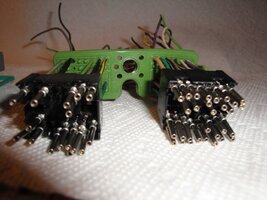
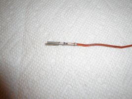
One of the images shows how I selected out one, thicker Orange Colored Wire that obviously is intended for carrying the Full 12 VDC versus the other wires which appear to a lot less ‘chubby’ and in all likelihood only have to carry 5 VDC for signaling and communication with all point and contacts within the Vehicle. The other significant observance here is how incredibly robust and “gummy” the Outer Connector Seal and the Inner Wire Matrix Guide Seal are… sort of an OD Green and apparently… virtually indestructible. The individual Wire Female Post Connectors also look very sturdy… nonetheless… being as tiny as they are… I’d suggest using a pair of Needle Nose Pliers when installing them onto and over the (4) requisite Male Pins once they are connected to the right source wires coming from the OBD2 Port.

When next I can attempt that portion… I will use some Black Heat Shrink Insulators and make them all as durable and protected from short circuiting as possible. I will attach just two images to this post; one that shows a‘straight down the barrel of the gun’ view of these blocks of Pins and the other is of a Single Female Pin Connector and attached Wire. I stress that it makes perfect sense to use just these individual Pin-Wires rather than attempting to De-engineer the brilliance Delphi brings to their manufacture of such lasting and functional components… and more or less, it allows me to take the EZ Way Out and still hope for absolute success when building the GYMKO Bench Test Harness in this abbreviated way. This may be one of those rare instance where my doing it thusly will make the doing of this job for anyone else interested in attempting it ...just as easy:

DSC01326.jpg

DSC01325.jpg
 
Last edited:
mrrsm

Original poster
Lifetime VIP Donor
Supporting Donor
Member
Oct 22, 2015
8,202
Tampa Bay Area
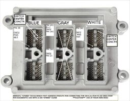
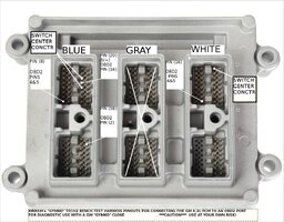
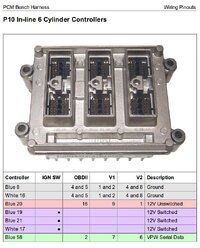
I spent some time this morning pondering the fact that the GM 4.2L P-10 Style Connector Diagrams for C1,C2 and C3 were showing the positions of each Pin as they sit inside of each Connector while looking straight down at them to give a True Positional Reference of them and indicate what they look like with each individual Pin-Wire poking through from the OUTSIDE of each Connector... But what they DO NOT Show is the PCM side of the interface which... unless I have my Spatial Orientation wrong.... should be a MIRROR-RORRIM Image of each Plug-In Connector...and therefore ... the Diagrammatic References for each of the (4) Special Pin Connection points for each of the In-Coming Wires (Female Pins) to the PCM will be BACKWARDS.

To clear up any confusion about what this means until I can dope out all of these weird realities and create a PCM Side Pin Attachment Image Map... I decided to create Mirror Images of all of the Original PCM Connectors and name them so... just to make sure that anybody building their own versions of this GYMKO Bench Test Cable does not go to all of this trouble only to find that they accidentally Burn Up their PCMs by not realizing that the two sides of the Interface between these components... are Dopplegangers. My advice is to wait until I set mine up and have a chance to test these ideas out on "Old Smokey" first... and either confirm that the cable works well with the "GYMKO Tech2 Scanner... or that it fails to do so. Please be assured that I will keep at it until I am certain that it all works reliably before saying that it is an absolutely Fool Proof GYMKO Bench Test Harness... (See the Attached Updated and Mirrored Images)
 

Attachments

  • img049AMIRRORED.jpg
    img049AMIRRORED.jpg
    133.7 KB · Views: 3
  • img050A.jpg
    img050A.jpg
    139.8 KB · Views: 3
  • img050AMIRRORED.jpg
    img050AMIRRORED.jpg
    141.7 KB · Views: 3
  • img051.jpg
    img051.jpg
    117.6 KB · Views: 3
  • img052AMIRRORED.jpg
    img052AMIRRORED.jpg
    111.9 KB · Views: 2
  • img049.jpg
    img049.jpg
    139.2 KB · Views: 3
  • img051AMIRRORED.jpg
    img051AMIRRORED.jpg
    112.1 KB · Views: 2
  • img052.jpg
    img052.jpg
    117.5 KB · Views: 2
Last edited:
mrrsm

Original poster
Lifetime VIP Donor
Supporting Donor
Member
Oct 22, 2015
8,202
Tampa Bay Area
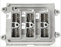
Okay... Just as I suspected... indeed the GM 4.2L PCM Pin-Out Diagram (which I have just finished preparing) is an actual "Mirror Image" of the Three BLUE, GRAY & WHITE Connectors. I was very careful to use a Flashlight shining through the front side of the "Positive Pin-Out" views of the Blue and White Connectors so I would have a better understanding of how to create the PCM Version and not make any mistakes with all of the bewildering possibilities staring right back at me. I have double and triple checked my referencing on this image so that I would not make any mistakes in Pin Choices and decided that for the sake of the Viewers and Users of this information... Laying out an overlay of those locations Literally in Black and Gray and White seems to make a lot of sense in helping to "PIN" Down the Connections coming from the OBD2 Port (Female... Pre-Wired) Connector. It only remains for me to finish the "autopsy" of the GRAY Connectors and after scavenging (4) Pins and Mocking Up their marriage to the OBD2 Port Harness Wires.

I will probably finish sorting out out those Pins to the OBD2 16 Pin Female Port and after Soldering Up and Heat Shrinking Down their Insulations... I'll Take a Deep Breath... then get out the New "GYMKO" Black Case and after setting everything up... I'll plug everything into this new GYMKO Bench Test Harness... Hook up the 12 VDC 1.5 Amp AC-DC House Power Adapter and Press the "ON" Button on the Scanner and just hope I don't get a "BSOD" or wind up Deep Fat Frying my New Scanner in the offing as a reward for all of my efforts. Fingers crossed... and I'll be certain to shoot plenty of images of the Soldering Mock Ups as well. If "Old Smokey" wakes up and behaves himself... I hope to have some good news (and some interesting Screen Shots) for everyone to see that this idea panned out ...and that if I can do it... anybody can.

FWIW... This has always been my philosophy: Don't EVER be Afraid to FAIL!

"A Ship in The Harbor... Is SAFE... But THAT is NOT What Ships are made for..."

GYMKOBENCHTESTHARNESSTOPCMPINOUTS.jpg
 
Last edited:
m.mcmillen

Member
Apr 29, 2016
556
Wisconsin
I made up one of these set ups a year or so ago just to see if I could re-flash a pcm. It worked BTW. When I first tried it out, I used a simple code reader to connect to it so if I messed up, I wouldn’t be out much.
 
  • Like
Reactions: mrrsm

mrrsm

Original poster
Lifetime VIP Donor
Supporting Donor
Member
Oct 22, 2015
8,202
Tampa Bay Area
Encouraging words, Brother... Was it for the same PCM? Does anything look wrong so far in the layout I am using right now that leaps out at you as being something I need to modify? Is there anything I can simplify further? My insistence on using only the OEM Pin Wires has to do with not wanting any of them to loosen up at any time during the Binary Hexadecimal Transfers if I do as you did to either Clone or re-flash this style of PCM.

I had thought about placing an inline Fuse for 3 Amps or lower using an Audio Style Glass Cylinder fuse in between the PCM and the OBD2 Port ... but with using the OEM 12 VDC @ 1.5 Amps I am hoping no damage will occur. If you still have your harness and it has this feature... it would helpful to see what you created. Using the Delphi sub-components is my own personal preference for this project... but that is not very encouraging to others to follow suit since the C1, C2 & C3 OEM Connectors are not ubiquitous... So a less expensive component “recipe” that will still offer reliability would be very welcome here. I always appreciate your ideas.
 

mrrsm

Original poster
Lifetime VIP Donor
Supporting Donor
Member
Oct 22, 2015
8,202
Tampa Bay Area
I'm irrationally superstitious about certain numbers... and since this posting will "Get Me Off The Schneid" of the worst combination among the 'rational numbers'... I'm adding this post so I can put it behind me and not be bothered by its presence as "The Number of The Beast".

It is probably a good thing that I haven’t got a linear inch of Rosin Core Tin Solder to my name right now so that I can Tin Solder the final Mock Up of the GYMKO Bench Test Harness… giving me enough pause to consider installing a (2) Amp Fuse Block on the B+ 12 VDC 1.5 Amp Hot Lead between the Pin (16) Red Wire leading from the back side of the OBD2 Port Connector over to Pin (20) on the PCM. Even after having no ordeal whatsoever in obtaining the Complete “GYMKO” Tech2 Scanner Kit from OBDFox via AliExpress… I’d still rather not lunch the Main Logic Board by mistake for the sake of a mere experimental idea when such protections are readily available and quite inexpensive as well.

This robust ‘Kit and Kaboodle’ contains what we should all have sitting silently under the Back Lids of our Trailblazers and Envoys, should the need arise for replacing a whole variety of Fuses on short notice... (...better to have them and NOT need Them... etc...) By having the Fused Link 18 Gauge Red Wires acting as an intermediary will make me feel a lot better when I finally ‘put the music on’ and power these things alive after completing the Harness:

https://www.amazon.com/dp/B075PNDW58/?tag=gmtnation-20
 

mrrsm

Original poster
Lifetime VIP Donor
Supporting Donor
Member
Oct 22, 2015
8,202
Tampa Bay Area
Considering that with the PCM and the “GYMKO” Tech2 would ordinarily be running off of a Cheap, plug-in style AC-DC 12 VDC @ 1.5 Amp Power Supply… I figure that in the advent that my GYMKO Bench Test Harness FAILS TO POWER BOTH UNITS with stability, then the option to modify the Test Harness to have its own a dedicated DC Input is a must to accommodate. Why take a chances when for a little more money…(Under $80.00)… I can have these other options easily available? Besides that… who knows how much Legacy Computer and Laptop Hardware I’ve got stacked up around in my office that can be run off of a device like this… capable of mixing and matching their often idiosyncratic power and amperage requirements… (18 Volts @ 3K mA? 21 Volts @1.5 Amps?) You get the idea.

THIS Eventek Variable Voltage (0-30 Volts) Variable Amperage (0-10 Amps) Power Supply will guarantee having a steady DC power stream to maintain these two items during testing and use. Considering the sensitivity that FLASH Programming places upon having ‘washed and metered’ electricity during the TIS2000 Laptop PASS-THRU operations… I think this device actually BELONGS on anyone’s Bench for doing this kind of work if they want to avoid “Bricking” their PCM(s). Eventek does make another version of this VPS for around $60.00 that handles 0-30 Volts @ 0-5 Amps… but I wanted the Higher 10 Amps capability in the advent of other requirements for testing use with different and/or more demanding DC electrical Components.

https://www.amazon.com/dp/B073TW8H2S/?tag=gmtnation-20

EVENTEKVPS.jpg
 

mrrsm

Original poster
Lifetime VIP Donor
Supporting Donor
Member
Oct 22, 2015
8,202
Tampa Bay Area
Okay... This afternoon... all of my new Soldering Supplies and a better Bench Soldering Iron HW came in around 2:30 PM EST so I laid out the GYMKO Bench Test Harness and soldered and Shrink Insulation Wrapped and Heat Gunned everything together nice and tight. It does not look like much as a finished product... but all of the Materials are High Quality and I am certain not to be putting any of the hardware (PCM AND "GYMKO" Tech2 Scanner) at risk for any unforeseen melt down issues. Subsequently, I used a large full screen print out of the PCM Pin-Outs I created for the purpose with the Overlay being used to refresh me on where the (4) Four Pin-Wires needed to be carefully inserted onto the PCM Pins. All of my best guesses about not cutting the wires neither too short and nor having them too long panned out perfectly. I also installed a Weather Pack In-Line 2 Amp Fuse for Peace of Mind. No special tools were necessary to perform the individual Pin insertions.

Next... Since I had a good open spot to lay everything out on my kitchen counter top... I decided to try out the Clone Tech2 with the wall AC-DC 110 Volt to 12 VDC @ 1.5 Amp Power Supply and see if the connected components would light up and work. Prior to that, I ensured that no power was connected to the Power Supply since presently... I followed the Build Schematic from EFILive and have no In-line ON/OFF Switch installed to prevent the direct flow of 12 VDC once the PS is plugged in. I wanted to have everything hooked up before plugging in the PS and the turning on the Tech2 Clone. That said... Once plugged into the wall outlet... The Power Supply Light came on and then I pressed the "ON" Button on the bottom right hand side of the Tech2 Scanner...and the Normal Blue Screen with past-post BIOS diagnostics came on and were running properly.

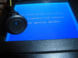
At this point I realized that without knowing the VIN to this PCM... I might not be able to follow the bouncing ball of the screens to run any Bench Diagnostics on this "Roasted PCM" just yet... and sure enough I hit a wall where I could not get the DLC to allow any communications without having an SUV wrapped around it and be plugged into the Truck Wiring harnesses. At one screen, the prompt advised to "Turn the Ignition Key to the ON Position..." so at this point I will have to step back and determine whether or not I'll have to add some sort of Ignition Key security bypass using a resistor of some sort to allow the thing to talk to the Tech2 Clone. I don't think it is a Power Issue, because the B+ Circuit from the OBD2 wiring works well enough to fire up the Tech2 Clone without any glitches and there were no screen flutters of power fluctuations when I commanded it to search for the PCM.

I don't know exactly what to do to remedy these issues yet... But I think I have something working here well enough to continue to sort these problems out and come up with a satisfying resulting Bench Diagnostic Harness. The progress today proves that my wire layout and pin-outs and connections seem to get along and that 12 VDC power is making it completely in and out of the PCM, with enough left over to run the Clone Hand-held Scanner. It may also just turn out that all of these problems are occurring because this unfortunate PCM was turned into a "Fire Brick" in some unknown wooded area prior to being salvaged already and so "Old Smokey" might be electronically Dead as a Door Nail. I'll need to investigate further and leave this matter as a partial success that needs quite a bit more thrashing out before I can declare a victory with this damned idea and I may need to ask @Bill Reid to scour what has been done and tell me if he sees any errors or has some other ideas that will remedy the situation.. See the Attached verification images on the project's progress to date:
 

Attachments

  • DSC01331.jpg
    DSC01331.jpg
    351.4 KB · Views: 13
  • DSC01332.jpg
    DSC01332.jpg
    450.7 KB · Views: 10
  • DSC01333.jpg
    DSC01333.jpg
    418.7 KB · Views: 9
  • DSC01334.jpg
    DSC01334.jpg
    421.2 KB · Views: 8
  • DSC01336.jpg
    DSC01336.jpg
    397.4 KB · Views: 8
  • DSC01338.jpg
    DSC01338.jpg
    411.4 KB · Views: 9
  • DSC01339.jpg
    DSC01339.jpg
    542.6 KB · Views: 11
  • DSC01340.jpg
    DSC01340.jpg
    634 KB · Views: 12
  • DSC01341.jpg
    DSC01341.jpg
    500.4 KB · Views: 11
  • DSC01342.jpg
    DSC01342.jpg
    592.8 KB · Views: 11
  • DSC01347.jpg
    DSC01347.jpg
    519.6 KB · Views: 11
  • DSC01348.jpg
    DSC01348.jpg
    447.1 KB · Views: 14
  • DSC01349.jpg
    DSC01349.jpg
    457.2 KB · Views: 13

mrrsm

Original poster
Lifetime VIP Donor
Supporting Donor
Member
Oct 22, 2015
8,202
Tampa Bay Area
Last night… I studied the Wiring and Harness Schematics designed and used successfully by @Bill Reid after visiting his Photobucket on this topic… I downloaded some of those originals he created and then snagged just a small portion I needed to clean up and isolate just the Switching Circuit. The idea was to convert what he documented on a much grander and enterprising scale in comparison to my small attempt at just establishing communications between the PCM alone… and the Clone Tech2 Scanner and make it easier for me to understand. Then I likewise printed out this edited version and after shining a bright flashlight through the paper from front to back… I was able to trace out the way these Wire Pin-Outs appear; not to the C1, C3 External Connectors, mind you… but on the PCM itself. This is what the foreshortened Schematic I edited for this purpose from his work looks like:

BULLREIDSSUBSET.png

...and THIS is what my adjusted PCM Schematic Pin-Out Image with the New Overlay looks like after the addition of this much needed modification of the Switched Power Feature. Apparently, the inclusion of this sub-circuit is quite necessary to be “switched” on at the point where the Clone Tech2 Screen Instructions displays, “Turn the Ignition Key to the “ON” Position...” assuming of course that this very Switch is playing a substitute role as the Key and Ignition Wiring inside of the SUV:


FINALGYMKOHARNESSPINOUTS.jpg

At the moment, I don’t happen to have the Three Connector Lighted Rocker Switch on hand… but after browsing Amazon and making up a modest shopping list order that included it ...and a few other electrical components that I might need in order to proceed… that stuff is on its way to me as of this writing. I doubt that I would have been able to figure this part out on my own… and so My Thanks and Kudos to @Bill Reid for his having plowed this ‘Electrical Field’ so thoroughly for the rest of us to appreciate.

The only defense against such a Genius… is to admire him….” Johann Wolfgang von Goethe
 
Last edited:

Mooseman

Moderator
Dec 4, 2011
26,026
Ottawa, ON
Since I had a good open spot to lay everything out on my kitchen counter top...

Ooooohhhhh. MRS_RSM must have liked that!
 
  • Like
  • Haha
Reactions: mrrsm and Redbeard

mrrsm

Original poster
Lifetime VIP Donor
Supporting Donor
Member
Oct 22, 2015
8,202
Tampa Bay Area
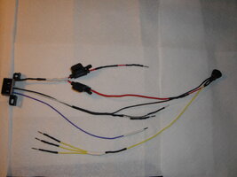
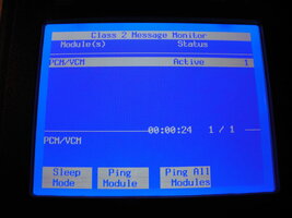
Well… to my very great surprise… IT WORKS! I took my time going over the original GYMKO (4) Wire Harness and added in the other (3) Switched Power Connections without making the harness too unruly. Compared to the very comprehensive apparatus that was designed and assembled by @Bill Reid into what would probably cost around $500.00 at bare minimum to have him prepare such a thing for purchase and use… Mine? Not so much… It is limited to powered Bi-Directional Communication JUST between the PCM and the “GYMKO” Tech2 Clone Scanners… and I realize that when it is laid out loose on the Bench… it pretty much looks like a Dog’s Breakfast... Until you PLUG IT IN and find out that IT WORKS!

For this Post… I have only attached (3) “Proof of Concept” images of the Finished Harness and showing that when all plugged in, everything worked properly with “GYMKO” Tech2 Screen Images showing that IT and the PCM were able to get along just fine. By the way… the Rocker Switch has an in-dwelling “Blue LED” that lets the User know whether or not it has been accidentally turned on prematurely... when it should be switched OFF until the Tech2 Clone is connected and Fired Up FIRST. I tested the interaction between the PCM and the Clone Scanner… both with and without the Rocker Switch being turned on… and everything worked perfectly. I’ve posted the rest of the Final Harness Design, Tech2 Screen Images and the HW set-up images over on my Photobucket site linked here below:

http://s557.photobucket.com/user/60...KOTECH2CLONE/PCMBENCHTOPHARNESS?sort=2&page=1

I tried to measure out and cut all of the remaining wires in relation to the New Rocker Switch first, so their addition to the existing Harness would not need very much if any modifications to pipe in the (+) Power and (-) Ground wires to the PCM. I used three more of the OEM Sacrificial C2 Pins necessary to make it all the proper Pin-Out Connections function. I decided that since the Three Position Rocker Switch is sub-powering the PCM Ignition Switch Circuitry and that adding in another 2 Amp Fuse-able Link branched to the New Switch (side by side) with the original made good sense... just to be on the safe side.

If you are going to construct this type of Harness… you will need to Pre-Cut and Pre-Arrange EVERYTHING and make certain that all of your various colored Heat Shrinkable Wire Insulation Tubes are likewise, also cut to size and then slid onto the various individual and bundled wires groups FIRST… well in advance of your careful soldering. Avoid using Too High of a Heat Setting on your Soldering Iron as the innards of the Rocker Switch will overheat and Melt itself to Death with too much exposure to High Temp… (ask me how I know…).

When it comes time to TEST IT OUT... Be sure to PLUG THE OEM HOUSE AC/DC POWER SUPPLY CONNECTOR INTO THE OBD2 PORT ADAPTER FEMALE POWER INSERT... AND NOT INTO THE BASE OF THE "GYMKO" CLONE ITSELF...OR THIS HARDWARE ARRANGEMENT WILL NOT WORK! In a few days from now... I'll spark up the Dell Precision M65 Dedicated TIS2000 Laptop and attempt some SPS software Serial Port Communication and experiment on "Old Smokey" just a little and see if I am able to do anything worthwhile with this Derilict PCM.

All of the Related Wiring Diagrams, Component Pin-Outs and Wiring Placement Images are also Posted for future reference on my Photobucket. They will be easy to refer to and anyone can Download, Print and Follow them by those who decide to create their own flavor of:

The GYMKO Bench-Test Harness

***Whew*** Man…. Am I glad THIS Project is Done!

PROOFOFCONECEPT0.jpg


FINALGYMKOHARNESSPINOUTS.jpg


PROOFOFCONECEPT2.jpg

PROOFOFCONCEPT1.jpg
 
Last edited:
m.mcmillen

Member
Apr 29, 2016
556
Wisconsin
Was it for the same PCM? Does anything look wrong so far in the layout I am using right now that leaps out at you as being something I need to modify? Is there anything I can simplify further?

Yes, it was the same PCM. I’m kind of wondering through, why didn’t you just use the factory harness to plug into the PCM?

I didn’t get too fancy with the wiring. It was actually quite the opposite. I used wire nuts on a lot of connections and an alligator clip for the switched power. I was really more or less wondering if I could figure it out.

Sorry for the late reply. I’ve been out bus driving all over and it has been pretty busy.
 
  • Like
Reactions: mrrsm

mrrsm

Original poster
Lifetime VIP Donor
Supporting Donor
Member
Oct 22, 2015
8,202
Tampa Bay Area
Hello Mac… Welcome Back... :>)

What was the reason I avoided using the C1,C2 &C3 Connectors? “OCCAM’S RAZOR”. Basically that idea posits that: “The Simplest Explanation of Anything… Is Almost 100 % … Correct.”

You and I and many other Members might have the perspicacity to to seek and find these rare (64) Pin Connectors (Xs two needed for this project)… But most people won’t be haunting any Automotive Bone Yards to run across them. With perhaps 1.5 Million Trailblazers and Envoys manufactured from 2002 and onwards… I do agree that there are probably quite a large percentage of them sadly, lying pavilion all around the Local Junk and Salvage Yards… but for this project… I wanted it to evolve into the most basic way possible to create a Harness that really can work using the ubiquitous OBD2 Wired Female Port, just handful of multi-colored wires, some solder and the skill with applying it, some heat shrink insulation and the time and patience it takes to read the images I created as a proper road map to connect the Harness up to the PCM. The hard part is done now… as long as the builders download those few necessary diagrams and images… it should be a walk in the park for anyone to assemble.

As for the Pins being scavenged from “Old Smokey’s” Delphi OEM Connectors? In this initial build… they were an absolute necessity because I did not want any sketchy electrical contact issues happening to ‘spoil the party’ once I powered up the whole apparatus. The Pins… Hmmm… Yes … I still have to measure the Length, Depth, ODs and IDs of the Male Pins on the PCM and the (fe)Male (with hollow Female inserts inside) Pins on the Harness Connector side. When I have figured out those dimensions, that problem can be sorted out and probably sourced for some basic solder-on equivalent(s) via the on-line Electronic Supply Houses as substitutes for the pins I “Frankensteined” out of the Three OEM Delphi Connectors, thereby making them unnecessary to complete the Harness Build.

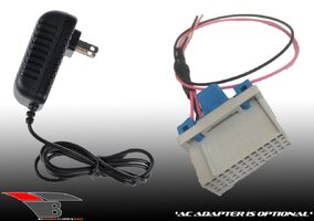
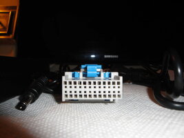
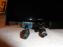
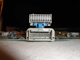
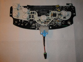
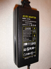
And getting back to the Origins of this Thread... since you ‘liked’ the the idea of the alternative, simple solution for diagnosing and repairing the Instrument Cluster versus using the “GYMKO” Tech2 Clone Scanner… I’ll mention here that last evening, the Special Delphi (24) Pin Adapter for the Instrument Cluster arrived after almost a two week delay. I was unprepared but very pleasantly surprised when I noticed how hefty the soft mailing package was for toting around such a lightweight connector… and opened it to find that the Vendor had not only thrown in the 12 VDC @ 5 Amps Power Supply, but he included the two proprietary plug-in connectors for the PS and the wiring leading to the (24) Pin Harness Main Logic Board Connector. I dragged out an Old Instrument Panel board that I’m certain came out of a Flood Vehicle and that I know to be Quite dead… just as a Prop to test how well the connector fits into the (24) Male Pin Socket on the board and found that it was decidedly correct and solid. I’ll have to rummage around a bit and find another panel that is at least barely working to test and shoot some additional images to prove that this Harness Adapter is not ‘Just Another Pretty Delphi Face’.

I powered up the PS and plugged the two special connectors together on the off chance that having 12 VDC @ 5 Amps might nudge it back to life… but unfortunately… No Soap. I took a raft of images and posted them on my Photobucket for everyone’s review. Initially I thought that the cost of this simple pre-wired (24) Pin Connector was a bit pricey at $35.00… but after receiving the device all wired up with connectors and the with power supply thrown in even though I failed to check the “Add Power Supply?” box on my order… THIS was a very satisfying outcome. In the future… I mean to study the Training Videos covered by the VOP (Video Original Poster) in Post #s 1-3 of this Thread… and perhaps fiddle around with my Weller Soldering Iron and try to resurrect another IC Board that is NOT as Manky as this Old Instrument Cluster MOBO turned out to be ...just for the Hell of it.

Now that BOTH Projects are done… I think what I would like to do is divide these Two Unrelated Projects in half...and create a New Thread that contains only the distilled essence of how to do these jobs without all of this wordy rubbish about the prelude of the design of The GYMKO Bench Test harness, et cetera ...and leave this Instrument Panel Diagnostic Thread here… all on its own.

http://s557.photobucket.com/user/60...EREPAIR/TRAILBLAZERINSTRCLUSTER?sort=2&page=1

DELPHINSTRCLSTRADAPTER1.jpgDELPHINSTRCLSTRADAPTER3.jpgDELPHINSTRCLSTRADAPTER4.jpgDELPHINSTRCLSTRADAPTER5.jpgDELPHINSTRCLSTRADAPTER7.jpgDELPHINSTRCLSTRADAPTER8.jpgDELPHINSTRCLSTRADAPTER9.jpgDELPHINSTRCLSTRADAPTER2.jpgDELPHINSTRCLSTRADAPTER10.jpgDELPHINSTRCLSTRADAPTER.jpg
 

Attachments

  • DELPHINSTRCLSTRADAPTER9.jpg
    DELPHINSTRCLSTRADAPTER9.jpg
    433.6 KB · Views: 6
Last edited:
mrrsm

Original poster
Lifetime VIP Donor
Supporting Donor
Member
Oct 22, 2015
8,202
Tampa Bay Area
Recently… @m.mcmillen (The Legendary Mac) raised an interesting question about my NOT using the PCM C1,C2 & C3 Delphi OEM Connectors… and I missed my chance when explaining in my reply that there are Three Features or Reasons present that would make me choose using the Discreet Pin-Wire Connections of the GYMKO Bench Test Harness over the use of the OEM Delphi Connectors:

(1) Ease Of Use: By following my PCM Pin-Out Diagram ...I can almost guarantee you that I can hook up the GYMKO Bench Test Harness Pin-Outs to the Gm 4.2L PCM in a Bench Top Setting… Faster and Easier than pretty much anyone trying to install just the Two-Out-Of-Three Delphi OEM Connectors and get everything ready to use.

(2) Modularity: Had my “GYMKO” Tech2 Scanner fired up and instantly recognized and accessed the PCM during my initial (4) Pin-Out Wire to PCM Schematic and Harness Build, I would not have come to appreciate having the ability to add in the Three Wire Switchable Link (Key/Ignition Circuit Substitute) that was needed to establish solid Bi-Directional Recognition between the PCM and the Clone Scanner. With that in mind… I realized that if it was the other way around… I would’ve had to once again completely take apart both C1 & C3 Connectors to accomplish the Three Wire Switched Link “add-in” and then put all of those parts back together again… What a PITA!

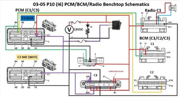
(3) Add-Ins: Having spent more than a little time looking over @Bill Reid ‘s work on his Schematics showing other Modular Connections such as the BCM and the Radio… I thought… WTH! I’ll check out eBay and Amazon and hopefully find a Cheap BCM to experiment upon and then re-arrange the necessary Wiring for the Add-In to the GYMKO Harness; extending the testing possibilities to include other Programmable Modules.

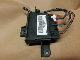
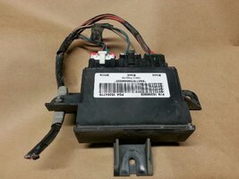
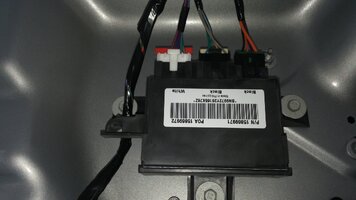
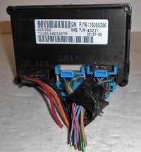
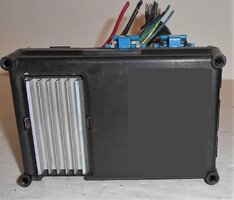
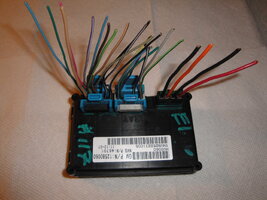
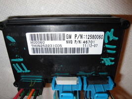
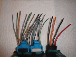
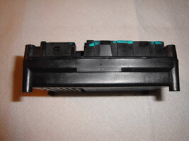
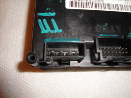
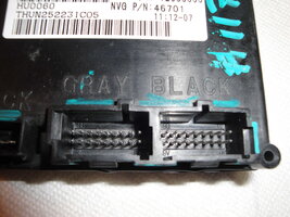
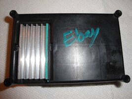
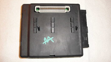
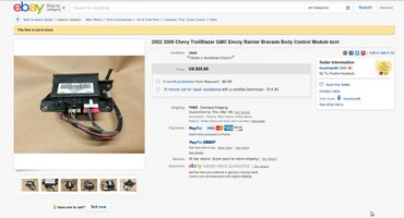
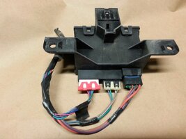
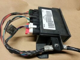
To that end… and for just under $26.00 with Free S&H… I located THIS GM Trailblazer-Envoy BCM ...which included The BCM… Three Harness Connectors, The OEM Wiring Pigtails and The Mount as a single Unit (See Attached Images). I bought it in hopes of adding it into the mix and allow for the chance of testing out using the GYMKO Bench Top Test Harness in a harmless way to learn how to use the SPS Programming coming FROM the Dell M65 TIS2000 Box… via PASSTHRU using the “GYMKO” Scanner and observe the Back and Forth, Give and Go between the Body Control Module and this whole innocuous Bench Test Harness apparatus... and see what happens.

If this effort works… it will extend my understanding SPS and it should be recognized here and now as an extension of the work @Bill Reid has previously done so well because I will be using HIS Schematic to re-design the GYMKO Bench Test Harness for the inclusion of the Add-In Module:

I Like It! :>)

Not ever having had the occasion to observe or service any BCM Components… I have yet to figure out whether the BCM I am getting off of eBay will be sufficient to prove out the idea that it and other Modules can be added to the Harness as needed and be tested over time. From the online research I did today and after watching the surprisingly edifying Youtube Videos covering the subject… These BCM Units seem to be are right up there with the PCMs in their enormous complexity. So if anybody can tell me whether this All Inclusive Unit I am getting is good enough to experiment with on its own… without requiring any other components, I’d like to know if this is the case. I love the fact that it LOOKS like it has everything included that I will need for this task… but I want to know for certain if this is true. Here is what is coming:

EBAYBCMSALE.jpgs-l1600E.jpgs-l1600D.jpgs-l1600A.jpgs-l1600.jpgBenchtop P10 Rev0_1.jpgs-l1600B.jpgs-l1600C.jpg
 
Last edited:
mrrsm

Original poster
Lifetime VIP Donor
Supporting Donor
Member
Oct 22, 2015
8,202
Tampa Bay Area
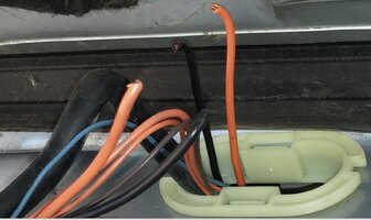
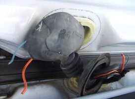
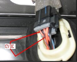
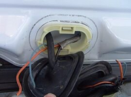
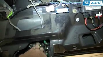
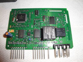
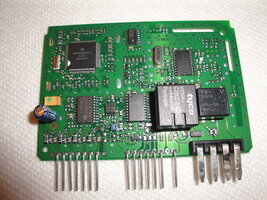
Okay... I am learning as I go... This Module is indeed a "BCM" ...but it is known more specificaly as an "LGM", as it turns out to be The Lift Gate Module and therefore is wired with greater simplicity than its more powerful and demanding brethren. I may not be able to do more with this thing than confirm communication between it and the "GYMKO" Scanner as I am not certain the SPS would do more than install the proper VIN inside to register it on the Vehicle Network. It is unfortunate that these attached images show the misfortune of a TB Owner who discovered after replacing the LGM and the Locking Mechanism of his Lift Gate without a solution, he later discovered that his problems occurred via the cutting of the harness wires nested in the tube and grommet seal between the Lift Gate and the Upper body of the SUV.

But we can profit from the fact that the OP of this issue took some excellent images of the wires openly exposed and this gives me a clue at to which of them are for (+) Power, (-) Ground and Signal Wires needed to perform Serial Data Communication with the "GYMKO" Scanner. If I can finish tracing these down... in the absence of having any available actual Pin-Out Diagrams of the Three Connectors of this LGM... at a minimum...I might be able to figure the correct Diagnostic Wiring of this thing... before the LGM component arrives via eBay:

LGMTHRUTHEBOOTWIRING.jpgLGMTHRUTHEBOOTWIRING1.jpgLGMTHRUTHEBOOTWIRING2.jpgLGMTHRUTHEBOOTWIRING3.jpg

LGM.jpg

LGMINSTALLED.jpgLGM.jpg
 

Attachments

  • LGM1.jpg
    LGM1.jpg
    259.3 KB · Views: 2
Last edited:
mrrsm

Original poster
Lifetime VIP Donor
Supporting Donor
Member
Oct 22, 2015
8,202
Tampa Bay Area
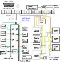
I was just thinking about the First Video in Post #1 of this Thread and I realized from a Still Shot Closeup that the VOP's "GYMKO" Scanner is NOT being parlayed through the Bench Top GM 4.2L PCM in conjunction with the Instrument Cluster... but rather it seems to be connected to Loom Connector Pad with the required wires running from the IC (24) Pin Wire Pigtails directly over to a dedicated OBD2 Female DLC Port... and the "GYMKO" plugs into it from that point.

So with this observation in mind... I see no reason not to use the second OBD2 Port Connector I have on hand to experiment by creating a separate, small dedicated harness... just to investigate the LGM (Lift Gate Module) All by its Lonesome! I'm still waiting for the eBay LGM order to arrive. Somewhere around here on this Linux Laptop... I have a Pretty Cool PDF that has a complete list of ALL the Modules for each of the GM Car Line and Light Truck Series that identifies ALL of the in-dwelling Modules on the there respective Vehicle Networks. I'll post that list up in here when I can find it. More to Follow...

EDIT:

Okay... Found them:

This Describes the Link for the Bosch J-XXXXX Tools and what their re-programming capabilities are:

https://www.boschdiagnostics.com/pro/j2534-faqs

....and this a PDF containing a list of (64) Pages full of the various GM Passenger Vehicles and SUVs showing what each of their re-programmable Named Modules are:

http://www.aa1car.com/library/gm_reprogrammable_modules.pdf

This is an interesting post from GMNT from way back in 2012 on the melting and failure of an LGM Unit with images the Circuit Board taken out of the case. When mine arrives and I can take it apart...perhaps the Logic Board has some Numbers I can cross-reference to find the Pin-Out designations for This Damned Thing:

https://gmtnation.com/forums/threads/almost-at-my-wits-end-with-the-lgm-please-help.5657/

One Last Link related to the re-programming update procedures involves this ACDelco TIS-Web Subscription Based Service Site for obtaining the latest updates. I am not sure it is necessary or if it even is currently working... but its a nice link to keep on hand, nonetheless:

https://www.acdelcotds.com/acdelco/action/home
 
Last edited:
mrrsm

Original poster
Lifetime VIP Donor
Supporting Donor
Member
Oct 22, 2015
8,202
Tampa Bay Area
This is an interesting video that correlates to that ACDelco TIS-Web Site:
https://www.acdelcotds.com/acdelco/action/home

... and in it, the Tech is actually using a separate PASS-THRU Device (it probably runs from $1,000 to $3,000) in order to Re-Program the PCM to solve a Phantom Code coming a Knock Sensor on a Chevrolet Cobalt, While not an actual "Bench Test" demonstration in line with what I am trying to accomplish... The Tech walks us through the use of the ACDelco login and PCM update as per the GM TSB on this problem using the ACDelco TIS-Web SPS System to Re-Program the PCM and get rid of the Cobalt's Code Error(s). In our situation... the "GYMKO" Tech2 Scanner connected to the TIS2000 Laptop set up would be the way to perform this task inside of the vehicle:


mrrsm

Original poster
Lifetime VIP Donor
Supporting Donor
Member
Oct 22, 2015
8,202
Tampa Bay Area
Okay… for any and all Users who have ever heard the word “Dongle” and besides laughing loudly and being momentarily distracted when saying the word out loud from the very real need to know about what this thing is and what it does… There is an Alternative. Besides the fact that in all of the History of Technology and being absurd to use, that name carries along with it the LEAST amount of insight as to "What The Hell is it supposed to MEAN?"

Well… Now we have an alternative expression that is ultimately much more memorable and descriptive when used in the context of setting up and using the TIS2000 Software on Users’ Laptop Computers. And now... people won’t look at you cockeyed when it becomes necessary to say it out loud and you hope to be taken seriously:

HWK” Designation Acronym Name = Hard Ware Key (Required during SW install and later SPS)
(I suppose it could be pronounced as… “Hawk”…..?)

And just so everyone knows, I only recently stumbled across this expression being used correctly in some other sites and blogs… but unfortunately, I never encountered from the very beginning of this “GYMKO” Trek and wish I had known about it sooner. I am tempted to go back through each and every prior post and edit that ridiculous “Dongle” word out of all required references ...save one ...just to mention the reason for its very deliberate deletion and the change in the expression over to HWK.

These are some additional Youtube Videos covering the Installation of the TIS2000 Software… One, albeit moving along at very high speed… but of such an extremely high quality that its lends itself to being played in SLO-MO as often as necessary to become very familiar with these procedures prior to committing to the actual TIS2000 installation onto Users’ Windows XP Pro SP3 Laptops:
TIS2000 Setup Instruction Video

How to Install a GM Tech2 TIS2000 USB Key:

Saab SPS “In Vehicle” Training Video:

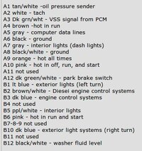
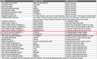
When the LGM from eBay gets here… my next task is to try and dope out the discreet Wire Harness Connectors necessary to attach to the OBD2 Female Port… and to that end, I copped this image from a more complicated table being used to set up a Keyless Wireless Entry and Alarm. The idea here is that without having a separate Connector Wiring Schematic… I have to resort to using a process of elimination to accomplish the task. This data relates to the LGM on a 2002 Trailblazer:

LGMWIRECOLORS.png
 
Last edited:
m.mcmillen

Member
Apr 29, 2016
556
Wisconsin
... and in it, the Tech is actually using a separate PASS-THRU Device (it probably runs from $1,000 to $3,000)

I use a pass-thru device and it is quite expensive. This is the one that I bought http://www.drewtech.com/technician/products/cdplus2.html I bought it because it will cover all US vehicles as far as re-flashing modules. It also covers many other OEM PC based scan tools (Honda, GM, and Toyota is what I use the most).

There is a cheaper option if you only want to stick with GM. http://www.drewtech.com/mongoose/gm2.html . I was just writing some long explanation about how this was a little more expensive option but there is good news! GM has changed their subscription packages! $40 for one specific vehicle for 24 months of service. That surely makes you think twice about having to go to a dealer and paying $100+ for them to do something. You can also now purchase Tech2Win for $249 instead of as a very expensive subscription.
 

Attachments

  • Screen Shot 2018-03-05 at 9.59.52 AM.png
    Screen Shot 2018-03-05 at 9.59.52 AM.png
    95 KB · Views: 9
  • Like
Reactions: mrrsm

mrrsm

Original poster
Lifetime VIP Donor
Supporting Donor
Member
Oct 22, 2015
8,202
Tampa Bay Area
Okay… A few words to the wise on the advance attack necessary before anyone attempts to simply blindly follow the trail of using this Harness or some version they build on there own by simply “Plugging In The Right Wires Into the Right Modules” and likewise attaching their “GYMKO” Clone Scanners and expecting all of the Best Readings to pop right up on the Blue Screen. This probably will not happen with anything that gets purchased off of eBay and more than likely … if they are investigating their own failed modules… the same results will probably occur.

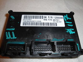
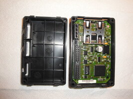
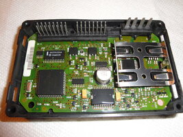
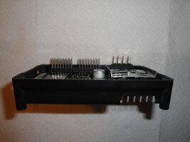
I cite this reality now after having received the eBay LGM (Lift Gate Module) for a 2002 Trailblazer and deciding to take the thing completely apart and examining each and every component for any existing problems that would throw the performance of the GYMKO Bench Test Harness into question when in fact testing any Modular Component without prior inspection for problems places ‘The Tester’ on a Fool’s Errand.

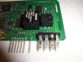
As I easily disassembled the LGM, I found damage and failure artifacts involved with what is probably called the C1 Black Connector in the form of extreme burning and melting on the Purple Heavy Caliber AWG Wire Blade of what must be the Primary 12 VDC Power and Ground Side of the Three Connector Plug configuration. I removed the PCB Circuit Board and looked over the surface mounted components and found nothing obvious in the way of swollen Capacitors or other burn marks to components… save the Galvanized Blade that services the said Purple Wire inside the Harness Connector. It showed signs consistent with repetitive Electrical Arcing between the Male Blade and the Female Internal Socket of the C1 Connector...which suffered from the same fate of Carbonizing and Melted Plastic of the Connector inside due to the sparking hot spot happening each time the circuit was activated. (See The Attached Images). Nothing will cause an Electrical Circuit to fail (...short of a "Dead Short") faster than a poorly made contact of higher amperage and strong current carrying ability... constantly trying to connect, break and then reconnect causing the contacts to get hot enough to burn everything around the arcs that occur in this manner.

Since the purpose of this purchase was to achieve a valid test of the Modular Interface between the “GYMKO” Scanner and the LGM… to avoid the ‘Mission Creep’ of having to rehabilitate this entire LGM as it fails to work on BOTH sides of the harness… instead I've found another identical LGM for even less money (under $15.00); again with Free S&H and I’m obtaining that item in lieu of trying to repair THIS one as a more practical approach to moving the Testing of the GYMKO Harness along.

While searching... I also came across a TCCM Module with a similar level of complexity, if not more so… but at least I will be able to find a decent TCCM Wiring Schematic of the Unit and the Module Connectors to dope out which wires will serve to be attached to a separate Test Harness (No PCM) as the (+) Positive (-) Negative and (S) Signal Wire wired to the OBD2 Female Port. Whichever one of these two Modules comes in first next will be the one I get back to work on for our purposes. The attached images give great evidence to “Look Before You Leap” by prematurely attaching such Damaged Modular Components to your version of this Harness and draw the wrong conclusions that any problems or malfunctions that occur afterwards are due to a poorly designed GYMKO Module Harness.
 

Attachments

  • DSC01451.jpg
    DSC01451.jpg
    633.3 KB · Views: 4
  • DSC01453.jpg
    DSC01453.jpg
    675 KB · Views: 4
  • DSC01455.jpg
    DSC01455.jpg
    396.9 KB · Views: 4
  • DSC01456.jpg
    DSC01456.jpg
    422 KB · Views: 4
  • DSC01461.jpg
    DSC01461.jpg
    407.1 KB · Views: 5
  • DSC01462.jpg
    DSC01462.jpg
    399.1 KB · Views: 5
  • DSC01463.jpg
    DSC01463.jpg
    389.5 KB · Views: 3
  • DSC01465.jpg
    DSC01465.jpg
    374.6 KB · Views: 6
  • DSC01466.jpg
    DSC01466.jpg
    424.3 KB · Views: 8
  • DSC01469.jpg
    DSC01469.jpg
    402.1 KB · Views: 5
  • DSC01471.jpg
    DSC01471.jpg
    407.1 KB · Views: 4
  • DSC01472.jpg
    DSC01472.jpg
    372.4 KB · Views: 4
  • DSC01450.jpg
    DSC01450.jpg
    457.2 KB · Views: 4
  • DSC01458.jpg
    DSC01458.jpg
    473.2 KB · Views: 3
Last edited:
mrrsm

Original poster
Lifetime VIP Donor
Supporting Donor
Member
Oct 22, 2015
8,202
Tampa Bay Area
This is a 64 Page List of the GM Re-Programmable Modules, Year by Year:

http://www.aa1car.com/library/gm_reprogrammable_modules.pdf

These images describe the TCCM (Transfer Case Shift Control Module) en route via eBay. The same careful inspection procedures awaits the arrival of this Module to sort out the bare minimum wiring prior necessary to design and building a separate GYMKO Bench Harness to interface with and examine it via the "GYMKO" tech2 Scanner:

s-l1600B.jpgs-l1600C.jpgs-l1600A.jpg2004ENVOYPROGRAMODULES.jpg2004TBPROGRAMODULES.jpg2007TBPROGRAMODULES.jpg2002ENVOYPROGRAMODULES.jpg2006TBPROGRAMODULES.jpg


These images cover the 2002-2007 TB, Envoy Re-Programmable Modules with variations per year listed:

2004ENVOYPROGRAMODULES.jpg
2004TBPROGRAMODULES.jpg
2007TBPROGRAMODULES.jpg
2006TBPROGRAMODULES.jpg
2002ENVOYPROGRAMODULES.jpg
 
Last edited:
mrrsm

Original poster
Lifetime VIP Donor
Supporting Donor
Member
Oct 22, 2015
8,202
Tampa Bay Area
Okay… Tonight, the 2nd LGM arrived from eBay and for costing only $14.95… it turns out to be in MUCH better condition than the first one was in and will now become the focus of my attention … at least until the TCCM finally arrives and then I can dive in and tear that one apart as well. Right now… The Big Mystery is… Why in The Name of God’s Holy Trousers… am I unable to find ANY specific LGM Connector Wire Pin-Out Diagrams to be able to decipher which one of “The BLUE Wires” is the Primary Network Signal Wire (and or the OTHER 5 Volt Low Reference if FOUR Wires are involved) needed to complete the basic Three or Four Wire Set Up needed to communicate with the “GYMKO” Scanner?

Really… Honestly… ALL I want to use this Damned Thing for is to continue to Add Several Different Modules to my Test Regimen and prove out this idea out that by using Simple, Discreet Module Wire-To-OBD2 Harnesses… any and all of these Modules can be interfaced with the GM Tech2 Clones using Class Two Data Streams and be adjusted or modified or uniquely REGISTERED on The Network of ANY appropriate vehicle by using the TIS2000 SW in a PASSTHRU configuration via the Dedicated Laptop; not inside any of the Trucks or SUVs during a Rain Storm Or a Snow Storm… BUT……...ON………THE…….BENCH!

Kansas Cows…! Why does THIS have to be so damned difficult? Fortunately… there are only about four different colors of “BLUE” amongst the Three Connectors available to test, but STILL… I am very reluctant to Power up the LGM Logic Board (which I know absolutely nothing about) and God Forbid, Screw up my Clone Scanner by grabbing the WRONG “Blue” Wire! These images will show a nice (better) contrast between the first LGM I picked up… and THIS one:

http://s557.photobucket.com/user/60dgrzbelow0/library/0000TRAILBLAZERENGINEREPA-IR/GMLIFTGATEMODULE?sort=2&page=1

More to Follow…
 

mrrsm

Original poster
Lifetime VIP Donor
Supporting Donor
Member
Oct 22, 2015
8,202
Tampa Bay Area
The General Motors TCCM (Transfer Case Shift Control Module) plays no part in its use on my 2WD 2002 Trailblazer… but nonetheless… I still like the idea of having the capacity to sit one of these units on top of my Bench ...and run Diagnostics and SPS PASS-THRU Updates if I decided to do so. Ergo... This makes THIS module perhaps even more important than the breakthrough use of my PCM GYMKO Bench Top Harness Success… precisely for the reason that IF I can get this simple Harness for the TCCM to function on this very basic “data-bus” between IT and a custom wired OBD2 Female Port chatting back and forth with my “GYMKO” Clone Scanner… the problem diagnosis and solving implications for the vastly greater numbers of 4WD Owners among our GMTN Membership could be very significant. Just imagine it... Having Your Very Own "Dealership" Capable Bench-Top Harness and Diagnostic Rig... right at your finger-tips!

To be honest, in the past… as far as having any Four Wheel Driving problems were concerned… I wouldn’t have pulled a hair to know more about how the Transfer Case, TCCM and Cabin Switching Mechanisms work. But having read many of the Absolute Horror Stories ever since then about people who live in Mountainous Terrain … losing Traction and Sliding Backwards over Ice Covered High Altitude Highways ... with The Abyss at their Elbows… it has given me enough pause to appreciate just how scary those event would be if I were driving a 4WD Trailblazer or Envoy and suddenly lost control of the vehicle. So my knowing as much as can be discovered here using this TCCM as yet another Modular Test Bed for study and updates using the “GYMKO” Scanner courtesy a Simple GYMKO Bench Harness ...seems very important to me now.

The attached images confirmed my suspicions that the TCCM ‘innards’ would have to made VERY robust to deal with the enormous electron flow and bi-directional communication traffic happening on the Logic Board, as well as having to dissipate the Thermal Overload that would occur if this thing was running the 4WD Three Ring Circus in Automatic Mode and there was no Heat-Sink to deal with this problem. My next foray into understanding how this device works electronically on the Network will be to use any updated Connector Pin-Out Diagrams I can find and try to figure out what the Basic Wiring for this GYMKO TCCM flavor Harness will turn out to be. Visit my Photobucket for the Complete Set of Images liked below:

http://s557.photobucket.com/user/60...0TRAILBLAZERENGINEREPAIR/GMTCCM?sort=3&page=1

More to Follow…

DSC01533.jpgDSC01534.jpgDSC01535.jpgDSC01538.jpgDSC01540.jpgDSC01541.jpgDSC01543.jpgDSC01544.jpgDSC01547.jpgDSC01548.jpgDSC01549.jpgDSC01550.jpgDSC01551.jpgDSC01552.jpgDSC01553.jpgDSC01554.jpgDSC01555.jpgDSC01556.jpgDSC01533.jpgDSC01536.jpg
 
Last edited:
mrrsm

Original poster
Lifetime VIP Donor
Supporting Donor
Member
Oct 22, 2015
8,202
Tampa Bay Area
These are a rare few Youtube using demonstrating “How to Use the “GYMKO” Tech2 SPS Feature to Download and Install an ECU Updates into the ECU/PCMs” … On The Bench:


This particular one is Pure Gold as it is a MUCH MORE INFORMATIVE VIDEO on Using BOTH the “GYMKO” SPS Technique AND the TIS2000 Laptop using the SPS PASS_THRU Feature(s):


While trying to track down the possible existence of an OEM Bench Test Harness, I found that one exists with the odd name of OBPA or The Bosch “Off Board Programming Adapter” Part # K&M J-41207-Cwhich seems to be a Bench Top EEPROM Re-Programming Device with Assorted Cable(s) that is interfaced by a GM Tech2 and will not be directly useful for the GMT360 Series of Vehicles. However, this Unit and its various harnesses would certainly find a home with anyone having vehicles that sport OBD1 PCMs that the Connectors would mate up… and perhaps lend itself to some slight modification to suit our purposes as well. I searched on-line for this rare “J” Tool and this ridiculously expensive TIS2000 EEPROM Based ECM Programming HW Kit came up:

http://www.autotoolworld.com/Kent-Moore-J-41207-C-Off-Board-Programming-Adapter-Kit-_p_210498.html

What follows in this first link are some of the most important Instructions I’ve located to date because this information guides the GM Technician Tech2 User through the proper steps for the attaching of and then turning certain of these components ON and OFF and in the Right Order so as NOT to damage either the GM Tech2… OR The PCMs involved. These Instructions may cause me to adjust how I use my own versions of the GYMKO Bench Top Harness(es) for the sake of protecting ALL the Equipment:

https://www.boschdiagnostics.com/pro/sites/pro/files/tech_2_obpa_users_guide.pdf

Here is another version of these Important Procedures and Instructions:

http://manualzz.com/doc/11173772/tech_2_obpa_users_guide

...and here is yet another Official GM PDF with Instructions and Part Numbers per Vehicles/VINs…. However… THIS Document explains a whole lot more about that was going on in the background if this industry that the General Public may not have understood way back then in 1997. It covers the apparent struggles of some Customers trying to explore what their rights were concerning Re-Flashing PCMs and ECMs. If ever there was Written Proof of how much GM held a Serious Death Grip on this Tech2 Re-Programming Market… THIS Document tells the story!:

https://ww2-secure.justanswer.com/u...8_INFORMATION_ON_REPROGRAMMING_CAPABILITY.pdf

These additional rare PDFs are also different are from what has already been collected and provided here by @Mooseman in the “Sticky” covering the OEM Documentation of the Use of the GM Tech2. I think that if these hold any informational value… they should be moved from here... over to his original thread covering the subject of Official Documentation.

http://www.pdfsdocuments2.com/t/54/tis-2000-software.pdf

http://www.obd2motor.com/download/tech2/TIS 2000 and SPS Install.pdf

http://www.obd2.com/support/reprog/downloads/gm/tis2000-req.pdf

http://www.townsendimports.com/Saab_TSB_Folder/Saab_TSB_pdfs/99_03_104.PDF

http://www.boschdiagnostics.com/dsoftware/Tech_2_OBPA_Users_Guide.pdf

This also covers some EASE Diagnostics Universal Programmer issues that need to be dealt with if the PCM is NOT being Bench Flashed!

http://www.obd2.com/support/reprog/reprog_issues.htm

http://www.obd2.com/support/reprog/reprog_vehicle-issues.htm

https://www.weber.edu/wsuimages/automotive/ASEP/CANdi Users Guide.pdf
 
Last edited:
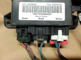
mrrsm

Original poster
Lifetime VIP Donor
Supporting Donor
Member
Oct 22, 2015
8,202
Tampa Bay Area
I can't believe my Good Luck in finally running into a proper C1,C2 & C3 TCCM Wire Pin-Out Diagram... and this one comes from a 2006 Buick Ranier, no less. But after scouring The 'Nets and coming up empty handed during the last few days... Getting my hands on THIS thing is a Welcome Sight! If you look over the diagram, starting at the Top Left area of the image.... You'll notice that I have isolated what I believe will be all of the necessary wires to mate up with the Female OBD2 Port wires... nested inside of a those few Red Rectangles. I'm not certain just yet... but I don't think I will need to add anything other than the (C1) Class 2 Serial Data Dark Green and White Wire, The (C3) Orange (+) Positive 12 VDC AWG Wire, The (C1) Black and White (-) Ground Wire and The (C3) Solid Black (-) Heavier Ground AWG Wires needed to make this thing work.

There may be a need to add in a Blue LED Lighted ON/OFF Switch to the Circuit and also a 5 VDC Low Voltage Reference Wire or Two from the (C2) Connector. But presently, I do not recognize such to be documented within this particular Diagram, as it is a dedicated, discreet Module that neither connects Directly With... nor Indirectly To (or through) the PCM in order to perform all of its functions. I am also going to stick with drawing Power to this setup for all of the hardware involved by connecting the GM OEM Tech2 Power Supply using the (+) Positive 12 VDC plug-in port to the outer DLC Cable Power Interface that I have already tried and proven out on the First GYMKO PCM Test Harness. Doing it this way will provide Power for BOTH The TCCM and The "GYMKO" Tech2 Scanner.

The reason for this is because, unlike the TCCM ordinarily nested inside of the Vehicle Under-Dash during the GM Dealership Diagnostic "In The SUV" scan" procedures, none of the ATC Gear Box Motor Hardware or Dashboard Switching Circuitry will be present "On The Bench" trying to draw additional voltage current flow (... neither the 10 Amps from the Fuse Box nor the (25) Amps needed for the ATC Motor Circuit) and stress out the GM Tech2 AC-DC Power Supply. I am curious as to whether the Security Circuit shown on this diagram will also be a problem... but right now, I'd rather not 'jinx' the thing before I've even had the chance to follow this Diagram and create a workable TCCM Bench Test Harness and then try to 'put the music' to the TCCM without having an SUV wrapped around it. As per good harness building practices... I will be adding in some (2-3) Amp In Line Fuses to protect everything in between in the event that I accidentally cross-wire anything.

All we need to do in this case is to be able to Power Up the TCCM first and then the "GYMKO" Tech2 Scanner to establish solid, Bi-directional Communications well enough to be able 'ping' this device using the "GYMKO" Scanner with the Harness acting as 'tiny-net data-bus' ... and if I can get THAT far... reading it On Screen with the TIS2000 Laptop while working with it via SPS PASSTHRU updates would be the Next and Final Step in proving that this second, unique GYMKO Bench Top Test Harness ...Works. I would urge anyone owning any flavors of the GMT360 Platform with Four Wheel Drive to snag and hang onto this very readable diagram if you are in the middle of sorting out your Transfer Case and TCCM woes right now... or expect to have any such trouble(s) with your 4WD system at any time in the future:


BESTCCMWIRE2PINOUTDIAGRAM.jpg
 
Last edited:
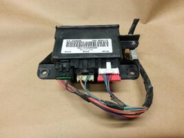
mrrsm

Original poster
Lifetime VIP Donor
Supporting Donor
Member
Oct 22, 2015
8,202
Tampa Bay Area
To add to the gradual and incremental understanding gathered so far as to how all of these Modules work on the Trailblazer, Envoy Data-Bus Network, I finally found the reason I was unable to locate the specific Pin-Out Diagrams for the LGM (Lift Gate Module) and OTHERS as well that behave and communicate using the very same rules set up for the PCM and BCM found on the GM Automotive Network: They are ALL listed on this next Diagram that shows the particular information that I require ...NOT just for the LGM Module... but for the other "Weaker Sisters" that also have to play well in this electronic environment. This is the most important question to answer in order to understand how to create Bench Top Diagnostic Wire Harnesses to communicate; either ALL... In Combination or as Single Modules between them ...and the "GYMKO" Tech2 Scanner via the OBD2 Female Port:

"Which Pin-Outs-to-Wires are Identified for EACH of the Individual Connectors on EACH of the Modules that will Carry the (+) 12 VDC... The Common Grounds... The LOW Reference Voltage Wires AND finally...The Class 2 Serial Data Information?"

This Question has NOT been very easy for to answer.... because I just assumed that for EACH and EVERY Module, they would have their very own Wire and Component Schematic, when in fact... they do not. But luckily, after re-visiting all of the related GM Factory Manual Wire Diagrams... I found that ALL of the "Questionable Connections" can be identified ...in Color...and with their Specific Pin-Wire attachments to Connectors... listed out and diagrammed on One Schematic... as shown in this attached image:

COMPUTERDATALINESYSTEM.jpeg

...and now that I can clearly see all of the Data Bus Lines and their Modular Connection points on the Network, I can work out how to build the remaining Harness(es) for The LGM Module... The TCCM Module ...and The BCM Module (The Official One, located under the Rear Seat). So once again... if you intend to build your own flavors of these harnesses, you will want to download and hang on to THIS image. I am still proceeding along on this project with the idea that it should not be absolutely necessary to establish network connections between and through the PCM or BCM in order to Read...and Write onto these individual Peripheral Modules. We shall soon see what happens when I try this idea out.
 

mrrsm

Original poster
Lifetime VIP Donor
Supporting Donor
Member
Oct 22, 2015
8,202
Tampa Bay Area
The “True” BCM came in late last night and once again, I took the time to clean it up, dis-assemble and re-assemble this portion that also requires a special Cable (on the way…) and a Fuse Block that is attached as well (not necessary for our Testing Purposes). THIS is the hardware that [@Bill[ Reid worked on to create his Special Harness and power set ups that are much more durable and manageable when assembled as he describes and using exterior Box Compartments and Switching which I intend to side-step using only the GYMKO Adaptive Bench Test Harness. I have attached the images of the BCM showing the various stages of its dis-assembly and re-assembly below:

For the Members presently enjoying the use of their “GYMKO” Scanners…. This italicized, excerpted information is arguably The Very Best Diagnostic Explanation to be found for describing what a Class 2 Serial Data Network is… and how it can go sideways. The Class 2 is the apparent favorite Networking Architecture being used in our GMT360s Vehicle Communications Networks and this article and link goes the extra mile in confirming that the Networks functions by using a “Single Wire” method that also Bundles and Pools the Data Lines leading to the Female OBD2 Port using “Splice Packs” to collect, connect and re-direct all of the Wiring that communicates with ALL of the on board Modules in a manner that makes perfect sense:

Let’s move onto the CLASS 2 Serial Data network. Some GM vehicles started using Class 2 Serial Data network system in 1995, which was also the phase-in year for ODB II. Since then, Class 2 is becoming GM’s predominant network system. Modules on this network system share information and each one can transmit and receive messages.
The following summarizes Class 2 Serial Data: The network uses a zero to Seven Volt signal; the voltage rests at Zero volts when there is NO communication; the transmitted data is a variable pulse width signal; Class 2 is found at Pin # 2 of the DLC, and is a single-wire network system; and GM uses what is referred to as a “splice-pack” to connect modules and the DLC to each other for network communication.

The Class 2 bus circuit number and the wire color for this system, each vary, according to the individual module(s). To diagnose this network system, you will require the following: A lab scope and scanner; a high-impedance DVOM; a component locater; a vehicle-specific wiring diagram, which is very important to have; and most importantly, a healthy dose of patience. To confirm if the network system is operating as it should, hook up the positive lead (Channel # 1) of the lab scope to Pin # 2 at the DLC and ground the lead connected to either Pin # 4 or to the chassis. Next set the voltage setting to Five Volts and the time base setting to 100 ms (recommended). With the ignition switch OFF, there should be NO data being transmitted (NO voltage). Now, turn on the ignition switch and you should see the following signal, as shown in
Diagram D. (Sorry... No Diagrams came over... I have attached Exemplar images to this Post instead fro a visual reference...)

If the signal you see is not as shown above, you can adjust the time – base setting of the lab scope, to your personal preference.
As with other network systems, this one has some interesting aspects to it which we should spend a little time on. For example, let’s say that a late-model GM pick-up is towed to your shop, with a “no-start” problem. You hook up the scanner, but cannot communicate with the PCM or TBC (Truck Body Computer). Now what? Using the wiring diagram, locate the ‘splice-pack’ connector. This will vary according to vehicle model and year and thus the need for a component locater as well. Once you have located it, unplug the cap assembly from the connector and try starting the vehicle. If it now runs, you have narrowed down the cause. It is a network system failure. How do you know this? Because removing the cap assembly isolates the PCM and the TBC from the network. The most probable cause of this problem may be one of the following (or a combination of them):


1. Class 2 is shorted to ‘power’
2. Class 2 is shorted to ‘ground’
3. A module is shorted internally and has directly affected the network.


You can now proceed with the necessary diagnostics, to identify the source of the problem(s). As a side point, I spoke with a technician who was trying to source the reason for a 12 Volt signal on the Class 2 network. The vehicle was towed to the shop, as a no-start. The vehicle was a 2002 GM pick-up. In this case, the diagnostic splice-pack was located behind the radio. After he removed the radio, and unplugged it from the harness, he noticed that the 12 Volts now disappeared and the truck started. It turns out that a dime had lodged itself inside the CD player cavity and had caused a 12 Volt feed to transfer onto the Class 2 network. The dime was promptly removed and returned to the customer, along with the diagnostic repair bill.”

https://www.autoserviceworld.com/ca...neral-motors-communications-network-problems/


"TRUE" BCM Tear-Down and Class 2 Network-Splice Pack Images:

DSC01609.jpgDSC01610.jpgDSC01614.jpgDSC01616.jpgDSC01618.jpgDSC01619.jpgDSC01620.jpgDSC01623.jpgDSC01625.jpgBCMCONNECTORS.jpg2008_GM_truck_protocol.jpg90SCORVETTESPLICEPACK.pngSPLICEPACKLEADING2OBD2PORT.jpgPCMNETWORKEDCOMPONENTS.jpgDATABUSDIAGRAM.jpegBCM2004DIAGRAM.jpeg
 
Last edited:
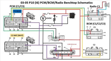
mrrsm

Original poster
Lifetime VIP Donor
Supporting Donor
Member
Oct 22, 2015
8,202
Tampa Bay Area
In order to create a separate GYMKO Bench Top “TRUE” BCM Test Harness… I’ll be using the information found within this BCM OEM Connector PDF to identify and wire up Two out of the Three Connectors that reside inside the SUV within the Rear Under Seat BCM – Fuse Box Harness to create something distinctly OEM that will be hard-wired and soldered from scratch. But... I will NOT be using any of the Very Expensive GM OEM Connectors that are available from the GM parts direct sourcing. Obtaining the usual, ‘Old Harness Cut-Off Connectors with Pigtails’ will be next to impossible out of Salvage Vehicles without having to extract the entire Interior Harnessing and pay for it as a complete set up and wind up making more trouble and work for myself than is actually necessary.

Instead, I’ll be using Mouser Electronics to purchase these ‘HTF’ Hard To Find Connectors using the Delphi Parts Numbers from the linked PDF and obtaining these Delphi connectors ...NOT for around the $60.00 amount they are asking for only one of these components…. But by purchasing TWO of everything; with the exception of the 40 PIN Bizarre Cable to Pin Connectors; ALL for Under $18.00 ... with S&H included from Mouser Electronics. So… If you need to locate VERY HARD TO FIND, OEM QUALITY CONNECTORS… Keep the link below to the Mouser Electronics site at your elbow and You Will Save Tons of Money!

http://tbssowners.com/docs/BCM_Connector_End_Views.pdf

https://www.mouser.com/?utm_source=...m=mouser electronics&utm_content=Brand Mouser
 

mrrsm

Original poster
Lifetime VIP Donor
Supporting Donor
Member
Oct 22, 2015
8,202
Tampa Bay Area
In Post #2 of this linked GMTN “P10-PCM Bench Top Harness” created by @Bill Reid, it was @Mooseman who said this:
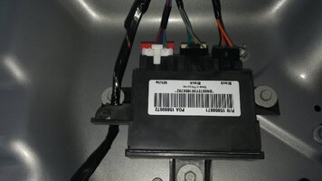
I even wonder if you need both hooked up to be able to program one of them. I'm definitely interested in this project.”

https://gmtnation.com/forums/threads/p10-pcm-benchtop-harness-with-bcm-radio-support.15270/

The research and the work I’ve put in to THIS Project so far more than bears out @Mooseman ‘s suspicion that hooking up each Sub-Module to to the PCM is completely unnecessary to “talk” to the GM Tech2 Scanner. However… I still owe it to @Bill Reid to try and re-create his work… But when using this GYMKO Adaptive Harness Design…Free from the requirement of using the Delphi OEM PCM C1, C2 & C3 Connectors and just using the PCM Built-In Pin Connections themselves as needed with discreet,external Pin-Wire Connectors; placing each one as needed onto the BLUE, GRAY and WHITE (NAT) Connection Points. Or… NOT… and by simply connecting to the proper 12 VDC Power, Ground and Network wiring of the Individual Modules as needed to program, they can all be accessed ...individually.

To help reduce the Wire and Pin-Out complexity from Bill’s excellent visual Schematic/Diagram, I figured it was necessary to try and Break Out ALL of the Pin References per Connector that are external to the PCM involving just the BCM and the Radio as described on his Primary Diagram. This approach is needed to simplify explaining what the wiring should look like with the ALL of the Cut Wire Segments, the Pin Connectors and the Color Auto Wiring and Colored Heat Shrink Insulators... laid out as loose components ‘On The Bench’ in preparation for Soldering each one of them into/onto the right places. I cannot stress how important @Bill Reid ‘s prior contributions and success back in 2016 with his Harness are to this Project!

This is what these arrays look like after comparing and linking the Alpha-Numeric BCM C1, C2 & C3 / Radio C1 Connectors versus their interface with the Numbered PCM Pin Connections. In each case, the “Hollow Male” Pins I scavenged from the PCM/Delphi GRAY (C2) Connector will be used for the PCM Connection-Side of this arrangement … and for the BCM Side… there are Small Pins needed for the C1 and C2 Connectors as well as for the Radio C1 Connectors. I have the two BCM Connectors on order. However, I am in possession of that strange BCM C3 40 Pin Connector that has a unique, Flexible Designed Cable with “A” and “B” sides having 20 Female receptacles per side that I can best describe as being “PIn-Serts”. These receptacles thankfully approximate the exact size of the familiar Small, Zinc-Plated Steel Paper-Clips (See the Attached Exemplar Images). I will be using these Small Paper Clips to create the discreet Soldered “PIn-Serts” strictly necessary to deal with the Special BCM C3 40 Pin Connector:

Additional Images are linked below on my Photobucket:

http://s557.photobucket.com/user/60...00TRAILBLAZERENGINEREPAIR/GMBCM?sort=3&page=1

BCM (C1) (Connector On Order)

A3 to PIN (20) PCM BLUE (12 VDC Red Wire)
B1 to PIN (59) PCM BLUE (Signal Wire Green)

BCM (C2) (Connector On Order)

F14 to PIN (58) PCM BLUE (Signal Wire Yellow)

BCM (C3) 40 Pin Connectors

Un-Switched 12 Volts Direct Current

A1, A2, B4, B13, B17 ALL to PIN (20) PCM BLUE or ENDS at 12 VDC via OBD2 PIN (16) (Red Wire)
A11 to Ground at PCM BLUE PIN (8)
B11 to Ground PCM WHITE PIN (16)

Switched 12 Volts Direct Current

A17,A18,A19,B15 to PCM BLUE PINS (19 & (21) and PCM WHITE PIN (17) ALL end at Center Connector of Rocker (Ignition) Switch
A11 to Ground at PCM BLUE PIN (8)
B11 to Ground at PCM WHITE PIN (16)

Radio (C1)

A1 to PIN (58) PCM BLUE (Signal Wire Yellow)
B1 to PIN (59) PCM BLUE (Signal Wire Green)
A8 to Speaker (Red Wire)
A9 to Speaker (Blue Wire)
A12 to Ground PCM WHITE PIN (16)

(ALL Green Wires link to Pin (2) of OBD2 Female Port for Class 2 Data Streams)


DSC01646.jpegDSC01647.jpegDSC01648.jpegDSC01651.jpegDSC01653.jpegDSC01655.jpegDSC01658.jpegDSC01659.jpegBILLREIDSBCMDIAGRAM.jpgDSC01645.jpegDSC01650.jpegDSC01625.jpeg
 

Forum Statistics

Threads
23,681
Posts
641,972
Members
19,138
Latest member
wentzben

Members Online