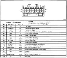
I've been spending that last day or so Beating The Living Hell out of an idea for making a GM Instrument Cluster Bench Test Harness to interface the "GYMKO" Tech2 Scanner for the purpose of Post Repair Testing of the Cluster Dial Sweeps and the Instrument Panel LEDs ...when I stumbled across THIS:
https://www.btdieselworks.com/products/instrument-cluster-bench-harness
There is an option at Checkout to purchase its own 12 VDC Power Supply, but that is easy enough to solve in so many other ways as well, Other than having a S&H Fee that is a bit steep at around $14.00 ... I doubt that I would have been able to do any better. While I can still use the "GYMKO" Tech2 Scanner to perform more extensive Tests of The Cluster if needs be by simply plugging it right back into the SUV Cluster harness Connector before completely assembling the components back inside of the casements... THIS handy thing will allow for Bench Testing it Before and After doing any repairs that will involve simple Repetitive Dial Sweeps and eye balling all of the Dash Light LEDs for proper working order...or burnouts... and NOT have to run back and forth to the Truck to perform these same tests:
These come in Two GM Flavors:
1999-2002
2003-2007


