its a new day and new year.... and actually now a different look at things based on the old year's last test ...

As I indicated a while back, when checking resistance especially on an unknown circuit, the first check is for voltage. This is "insurance" to prevent possible meter damage BUT also to prevent FALSE resistance readings... :-(
In this case, I think there is a false resistance reading of 9.3.
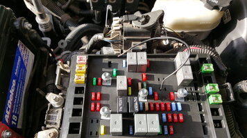
Basically, I think if Rad measure the "wired relay socket point" with a meter, he will find when attempting to crank, that the point is at 12.x volts (basically battery) and not ground. That is why the test light DOES NOT light because there is no voltage difference between the battery connection that the test light is hooked to and the test point. When there is no crank, there is nothing at the test point and hence the test light doesn't light then either.
So the mystery of why the vehicle doesn't start is because the relay coil does not get voltage (difference) provided to it by the PCM.
However, since the PCM is doing something during a crank, it appears to know that some stimulus (start voltage input) has happened causing it to change the output for the relay coil control from nothing to high voltage.
Further with the jumping using the "telephone wire connected to the relay control point and ground" causing a start, results in a quickly dying engine and theft light, which might be correct.
I am thinking that scenario happened like this.
Initial problem with "wife" was failed to crank / wonky instruments. Jump starting worked. Jumping at relay pins and such results in start, etc. Conclusion, replace switch. Switch doesn't get things working correctly, but appears to correct some things like wonky instruments. Now further testing get to this point with lots of checks of wiring and swap of cards. Results are basically the same, no start but the same for both pcm's.
That would point to either two failed pcm's, loss of "theft prevention understanding", or potentially improperly installed ignition switch.
I doubt there are two failed pcm's. Probably the "theft prevention" issue might be a cause or the ignition system is not installed correctly to allow the passlock system (what system is in this vehicle?) to function correctly.
As suggested by others, try the relearn first.