PO442

mrrsm

Lifetime VIP Donor
Supporting Donor
Member
Oct 22, 2015
7,926
Tampa Bay Area
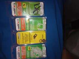
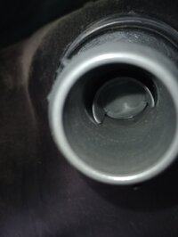
Yes... The MOST Positive Rust Prevention possible is by protecting Bare Mild Steel and Cast Iron using a Passive Zinc Metal Etching when treating those surfaces using THIS Strong Zinc-Acid Metal Etching Liquid called POR-15 "Metal Prep"...when VERY carefully applied with a cut-down Turkey Basting Brush.

Likewise ...the Bare Metal must first be washed off using the Special POR-15 De-Greasing Detergent via a Sponge and then later washing it away using Warm Water and hand drying using Scott "Blue" Shop Towels or hitting it lightly with a Blow Drier to avoid rapid rusting in the air.

Then immediately afterwards, for around 30-45 Minutes, apply the Wet Brushing of this Acid so as to deposit a Thin, Durable, Bonded Zinc Coating in place of the Normal Oxidation that occurs when Iron combines with Oxygen to form FE203 (RED RUST).

It is important to keep the Surfaces being so treated very "WET" the entire time when applying the "Metal Prep" Liquid throughout this procedure to ensure a Chemical Zinc "Etching Chemistry" Transfer.


81zoh8TWCLL._AC_SL1500_.jpg713wT5b-XJL._AC_SL1500_.jpg

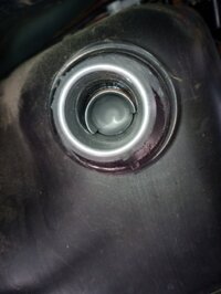
Once the Mild Steel is thusly Chemically "RUSTED" ...it will NOT degrade...and in fact this process will also allow for the item to be likewise Very Carefully Painted with POR-15 Black, Hard Paint via THIS Kit which has All Three Components along with the Bristle Brush, paint Applicator and Rubber Gloves necessary for this Complete Job. THIS is a much more economical approach to the work, since "A VERY Little POR-15 ... Goes a VERY Long Way... " Of course, every last vestige of the "Metal Prep" Acid must be carefully washed off of the Metal areas and then dried prior to being painted with POR-15.

As you know... ordinary Paint will NOT stick to these unprepared Ferrous - Iron Surfaces: There are MANY On Topic YT Videos showing all of these procedures on various projects, both large and small... along with the Caution and Warning NOT to get this Paint on Human Skin as once it dries... must WEAR off over time in order to remove it


71vNkjQJbBL._AC_SL1500_.jpg71cZTSAls5L._AC_SL1200_.jpg61YsyK+G3LL._AC_SL1200_.jpg
 
Last edited:
  • Like
Reactions: Stuntmanmike1977

Mooseman

Moderator
Dec 4, 2011
25,601
Ottawa, ON
I've always painted the top. Just tape off the connections. You can also certainly Fluid Film it.

Sorry, no part numbers. Like I said, those O-rings aren't available separately. You could buy another Dorman connector and use the rings in it on your old connector.
 

Mooseman

Moderator
Dec 4, 2011
25,601
Ottawa, ON
Good 'ol Dorman!
 
  • Like
Reactions: mrrsm

Stuntmanmike1977

Original poster
Member
Nov 21, 2021
145
Sanford, Maine
Took apart the filler hose to check for obstructions and make sure the flapper was free. Also changed the fuel tank pressure sensor. Hit the flapper over a dozen times and it is free and springed back shut. We'll see what happens at the pump. Does this look normal?
 

Attachments

  • IMG_20240615_142729852.jpg
    IMG_20240615_142729852.jpg
    189.5 KB · Views: 4
  • IMG_20240615_142505350.jpg
    IMG_20240615_142505350.jpg
    327.9 KB · Views: 4

Stuntmanmike1977

Original poster
Member
Nov 21, 2021
145
Sanford, Maine
Still don't work. I'll blow out the air line from the canister to the vent valve in the back before I put the new one on. Any way with the gauge reading full sending signal to the other sensors to shut down because the computer thinks it's full? Grasping at straws at this point. I can't even fill it with a gas can!
 

mrrsm

Lifetime VIP Donor
Supporting Donor
Member
Oct 22, 2015
7,926
Tampa Bay Area
It might be time to look for a complete Used Fuel Tank (assuming that Salvage Yards still sell them as such) and then "Bench-Top" Re-Build it from Scratch.. .or at the very least... try to scavenge the OEM EVAP and Fuel Lines from any available at the Yards.
 

Aroc

Member
Jun 1, 2023
16
NY
It may have been covered before but if you still have access to the fuel level sender assembly recommend taking a volt ohm meter to measure the resistance at the harness terminals as you move the float from empty to full position. See range specs below to confirm it increases at smoothly as you move the float.

For 2002-2004
Empty - 40ohms; Full - 250ohms
Gray-power 12V;
Black- ground;
Orange/Black- low ref fuel level;
Purple- fuel level signal.

Connect ohmmeter across o/b and purple.
 
Last edited:

mrrsm

Lifetime VIP Donor
Supporting Donor
Member
Oct 22, 2015
7,926
Tampa Bay Area
Agree with that premise, too. However... What @Aroc mentioned above... was verified back in Post # 16-19 in the first 20 Images I posted after entering in the OP's particular 2003 Trailblazer into my Snap-On Vantage Pro... and then posted ALL 64 of the consecutive OEM Shop Quality Professional Diagnostic Information afterwards in Screen Image Batches. This Image (#13 out of the First 20 Images) covers that particular Ohms Level information in the "TECHNOTES" Box:

IMG_9104.JPG

Fuel Level Drop Out Signals can only be detected using an Oscilloscope sensitive enough to pick up these subtle and very rapid events.

The majority of the First 20 Images well describe where to find the Fuel Pump and Sender, their Purpose and Function and the arrangement of the Connector Pin-Outs, their Circuits and Color Coding for the said methods of Testing and Back Probing using either a DVOM, a DMM or via Oscilloscope Measurements.
 
Last edited:
  • Like
Reactions: Aroc and TJBaker57

Aroc

Member
Jun 1, 2023
16
NY
Somewhere on this site we recently discovered and confirmed all years are NOT the same.
Thanks TJ. Updated my post to show years 2002-2004 when they had the same p/n and horizontal harness plug connector. I can confirm these specs were right on when i R&R my rotted out Fuel Pump Assm .
In 2005 they changed to square connectors.

The OP may have a clogged line issue but could also diagnose/fix the level sending issue while tank is out.
 
  • Like
Reactions: TJBaker57

Aroc

Member
Jun 1, 2023
16
NY
Still don't work. I'll blow out the air line from the canister to the vent valve in the back before I put the new one on. Any way with the gauge reading full sending signal to the other sensors to shut down because the computer thinks it's full? Grasping at straws at this point. I can't even fill it with a gas can!
When you say still didn't work was this after reassembling tank to underbody and trying to refill.

BTW, OEM part for the early GMT360s were Bosch units.
 

Stuntmanmike1977

Original poster
Member
Nov 21, 2021
145
Sanford, Maine
Still don't have anywhere to drop the tank and can't gain access to the plugs or wiring cause everything is on top of the tank. Someone worked on this before me and God only knows what they did. The pump is only 3 years old. Just going through wiring from the PCM and replacing all the EVAP sensors since they are 21 years old. I'm going back under it soon today so, if something is out of wack that I can see I'll take some pics and see if I have access to the ground strap from the sender unit on the frame. Was going to go with the new aluminum type filler nipple but, I don't think that will solve anything. The tank in my truck is also 3 years old. Kept leaking out the back after the shop did it. After the fifth trip back they just put a new tank in and they ate it.
 

Aroc

Member
Jun 1, 2023
16
NY
Still don't have anywhere to drop the tank and can't gain access to the plugs or wiring cause everything is on top of the tank. Someone worked on this before me and God only knows what they did. The pump is only 3 years old. Just going through wiring from the PCM and replacing all the EVAP sensors since they are 21 years old. I'm going back under it soon today so, if something is out of wack that I can see I'll take some pics and see if I have access to the ground strap from the sender unit on the frame. Was going to go with the new aluminum type filler nipple but, I don't think that will solve anything. The tank in my truck is also 3 years old. Kept leaking out the back after the shop did it. After the fifth trip back they just put a new tank in and they ate it.
When you get access to top of tank you can trace the colored harness wire to determine which terminals to check for fuel sender low reference and fuel level signal (it will determine what resistance the pcm is receiving). You could also do same for replacement fuel sender assembly before install.

Take care when removing plastics clips since if intact they can be reused provided they were not damaged previously.

The hard part for me were the strap bolts. Lots of PB blaster and patience loosing and tightening to break off the rust welds.
 

Stuntmanmike1977

Original poster
Member
Nov 21, 2021
145
Sanford, Maine
Got the new vent solenoid in and blew out the line, all clear and nothing came out. Also while under there soaked the strap bolts with PB blaster the heads and the threads through the holes in the frame. Also got the ground wire for the fuel/sender unit off and wire wheeled that clean. The only thing I could not do was the vacuum purge solenoid the engine. Can't get the clips off. Also, don't know if it matters but I think the shop put in an AC Delco fuel tank.
 

Attachments

  • IMG_20240616_144416649.jpg
    IMG_20240616_144416649.jpg
    521.5 KB · Views: 3

mrrsm

Lifetime VIP Donor
Supporting Donor
Member
Oct 22, 2015
7,926
Tampa Bay Area
Very Much..Indeed... and so much more...

The caution is to know which circuits must NOT be Tested using an Incandescent Test Light meant for LOADING up the Circuits under scrutiny...and use instead a Low Power LED version such as when *Tinkering* with the PCM and BCM.

But when it comes to Automotive Electrical Circuit Diagnostics... find links to sites like THIS one below to become better acquainted with the one thing that can prove out things like "Electrical Continuity" and "DIM Bulbs versus Bright Bulbs" on circuits compromised by Low Amperage and High Resistance...and of course, finding completely "Open Circuits" with mere touches to their electrical pins and contacts.

YT is your BFF for seeing these devices at play under the guidance of the likes of Eric "O" from SMA (South Main Auto), Paul "Scanner" Danner and his Brother James and of course, the ever redoubtable "Eric The Car Guy" to offer guidance on their many uses and methods for diagnostics.


  • Like
Reactions: Stuntmanmike1977

Aroc

Member
Jun 1, 2023
16
NY
Got the new vent solenoid in and blew out the line, all clear and nothing came out. Also while under there soaked the strap bolts with PB blaster the heads and the threads through the holes in the frame. Also got the ground wire for the fuel/sender unit off and wire wheeled that clean. The only thing I could not do was the vacuum purge solenoid the engine. Can't get the clips off. Also, don't know if it matters but I think the shop put in an AC Delco fuel tank.
The purge solenoid default is closed so can be left after tank/fuel sender operation is patched up. A large flat head screwdriver pushing down and to the side of the middle metal tab will allow the release of the purge solenoid from bracket.

That tank p/n does not show on gm parts list. If tank fits in frame and fuel pump sender assembly fits snug into recess cavity with float clearance you may be able to make it work if not completely accurate. Here are screenshots of 2002-2003 trailblazer fuel tank p/n 15077622 with slot for external fuel filter.
 

Attachments

  • Screenshot_20240616_191657_Firefox.jpg
    Screenshot_20240616_191657_Firefox.jpg
    139.7 KB · Views: 3
  • Screenshot_20240616_191829_Firefox.jpg
    Screenshot_20240616_191829_Firefox.jpg
    172 KB · Views: 3
  • Screenshot_20240616_192032_Firefox.jpg
    Screenshot_20240616_192032_Firefox.jpg
    135.2 KB · Views: 3
Last edited:
  • Like
Reactions: Stuntmanmike1977

Aroc

Member
Jun 1, 2023
16
NY
Got the new vent solenoid in and blew out the line, all clear and nothing came out. Also while under there soaked the strap bolts with PB blaster the heads and the threads through the holes in the frame. Also got the ground wire for the fuel/sender unit off and wire wheeled that clean. The only thing I could not do was the vacuum purge solenoid the engine. Can't get the clips off. Also, don't know if it matters but I think the shop put in an AC Delco fuel tank.
Found some info on the fuel tank p/n 15229311. It is very similar to 2002-2003 trailblazer fuel tank p/n 15077622 but has more capacity on the front end of the tank. You may have the 22 gal version of the fuel tank so it will work with the new fuel pump assembly.
 

Attachments

  • Screenshot_20240616_200733_Firefox.jpg
    Screenshot_20240616_200733_Firefox.jpg
    122.1 KB · Views: 2
  • Screenshot_20240616_201559_Firefox.jpg
    Screenshot_20240616_201559_Firefox.jpg
    124.1 KB · Views: 2
Last edited:
  • Like
Reactions: Stuntmanmike1977

azswiss

Member
May 23, 2021
937
Tempe, AZ
Seems to me that it would have to use the capacity value in order to calculate Range since the fuel level sensor readout is going to be a fraction, not a volume.

Range = MPG * Fuel Remaining where Fuel Remaining = Fuel Level * Capacity.

Edit: This assumes a linear relationship between fuel level readout & amount of fuel remaining which might not be valid if the tank is irregularly shaped.
 
Last edited:

Stuntmanmike1977

Original poster
Member
Nov 21, 2021
145
Sanford, Maine
The purge solenoid default is closed so can be left after tank/fuel sender operation is patched up. A large flat head screwdriver pushing down and to the side of the middle metal tab will allow the release of the purge solenoid from bracket.

That tank p/n does not show on gm parts list. If tank fits in frame and fuel pump sender assembly fits snug into recess cavity with float clearance you may be able to make it work if not completely accurate. Here are screenshots of 2002-2003 trailblazer fuel tank p/n 15077622 with slot for external fuel filter.
Are you talking about the purge solenoid on the side of the engine block? That's the one I was having trouble with. The hose connections I couldn't get off. I know about the tab to slide the sensor off but, on the one line one of the push release tabs is under part of the sensor. Tried turning it for access but, the line for the sensor is in the same plastic bracket as the fuel lines so trying not to put too much pressure on it. Might take the wheel off and try it from underneath. The vent valve in the back of the tank it replaced today, was actually coming apart with the slightest tug.
 

budwich

Member
Jun 16, 2013
2,082
kanata
Still don't work. I'll blow out the air line from the canister to the vent valve in the back before I put the new one on. Any way with the gauge reading full sending signal to the other sensors to shut down because the computer thinks it's full? Grasping at straws at this point. I can't even fill it with a gas can!
:-( do you have any kind of data reader to read pressures in the tank with key on?

Can you fashion some sort of "funnel cup" to fit over the inlet filler tube to allow you to blow in the tank to get an idea of what might be happening?

IF you get a data reader, you should see some pressure change.

When you say you can't even use a gas can to put gas in... how much gas goes in before it is "back splashing"?
 

Aroc

Member
Jun 1, 2023
16
NY
Are you talking about the purge solenoid on the side of the engine block? That's the one I was having trouble with. The hose connections I couldn't get off. I know about the tab to slide the sensor off but, on the one line one of the push release tabs is under part of the sensor. Tried turning it for access but, the line for the sensor is in the same plastic bracket as the fuel lines so trying not to put too much pressure on it. Might take the wheel off and try it from underneath. The vent valve in the back of the tank it replaced today, was actually coming apart with the slightest tug.
The purge solenoid hose connector toward front of engine with the push tab has a groove that you slide the tab all the way to the other stop on other side of hose. Just have to shift the tab back and forth until it releases.
 

Stuntmanmike1977

Original poster
Member
Nov 21, 2021
145
Sanford, Maine
:-( do you have any kind of data reader to read pressures in the tank with key on?

Can you fashion some sort of "funnel cup" to fit over the inlet filler tube to allow you to blow in the tank to get an idea of what might be happening?

IF you get a data reader, you should see some pressure change.

When you say you can't even use a gas can to put gas in... how much gas goes in before it is "back splashing"?
About half a gallon till I have to wait. Can hear it trickle into the gas tank.
 

Stuntmanmike1977

Original poster
Member
Nov 21, 2021
145
Sanford, Maine
Before I tackle this job and not understanding much about the testing process, is there any wires coming straight from the PCM that I can back probe to see what the computer is sending through the wires to the sender? Some charts say wire pin 22 but not sure. Can I put a lead on the purple wire and the other to a common ground? Just hate to do this job and have the same problem. I'm not good with diagnostics as all of you can tell by now. I have a test light and a very basic multimeter. Still no check engine light.
 

budwich

Member
Jun 16, 2013
2,082
kanata
not sure if there is any "anti-siphon" stuff in the filler, but you could try getting a relatively small hard plastic / copper tube without dropping into the tank (ie. make sure it is LONGER than the full length of the filler plus tank base and send it down the filler. Hopefully, you can then have your gas can fill test to see if that helps with in flow.

In terms of meter testing, get an ohm meter and find the signal pin of the sensor and ground wire to measure the resistance as posted earlier... with key off. That reading should be less the 250 ohms.
 

Stuntmanmike1977

Original poster
Member
Nov 21, 2021
145
Sanford, Maine
not sure if there is any "anti-siphon" stuff in the filler, but you could try getting a relatively small hard plastic / copper tube without dropping into the tank (ie. make sure it is LONGER than the full length of the filler plus tank base and send it down the filler. Hopefully, you can then have your gas can fill test to see if that helps with in flow.

In terms of meter testing, get an ohm meter and find the signal pin of the sensor and ground wire to measure the resistance as posted earlier... with key off. That reading should be less the 250 ohms.
There are 3 wire clusters bolted to the PCM. Which cluster are the sender wires in? Can't find a diagram of the sender wires to the PCM.
 

Stuntmanmike1977

Original poster
Member
Nov 21, 2021
145
Sanford, Maine
I know I asked this before but I know the top of these fuel pumps rust fairly quick. Ok to shoot it with fluid film after it's assembled and right before it's put back up in place? Asking because says it has penetration properties. That wouldn't loosen the lines would it? And obviously would cover the wire connector before I coat it.
 

mrrsm

Lifetime VIP Donor
Supporting Donor
Member
Oct 22, 2015
7,926
Tampa Bay Area
FLUIDFILM1.jpg
 

Attachments

  • FAQ - Fluid Film.pdf
    387.2 KB · Views: 0

Mooseman

Moderator
Dec 4, 2011
25,601
Ottawa, ON
I wouldn't worry about using FF. It wouldn't penetrate past the rubber seals.
 
  • Like
Reactions: Stuntmanmike1977

budwich

Member
Jun 16, 2013
2,082
kanata
There are 3 wire clusters bolted to the PCM. Which cluster are the sender wires in? Can't find a diagram of the sender wires to the PCM.
the signal wire back to the pcm is on c1 pin 22 while the low reference is on c1 pin 8. Those are the two that you need to put your meter on to get a resistance reading of the fuel level sensor. Be careful how you probe the pcm connector as too large a probe may damage the pin "hole".
 

TJBaker57

Member
Aug 16, 2015
2,936
Colorado
Here is some information that should be useful.

First a schematic of the 2003 fuel pump and sender system. (hope that is the right year though other will likely be similar)


In that diagram note the wires pass through the C101 connector. That connector is adjacent to the under hood fuse block. More easily probed than a PCM connector I think. Note the connector terminal are C12 and D1.

Here is a pinout for that C101connector...


Last we have a chart for the resistance readings that may be expected...


Edit: I will add that I checked a 2003 PCM yesterday with a DMM and found the signal voltage from the PCM on the ppl wire was just under 5 volts. This was tested on a PCM harness while disconnected from any level sender.
 

budwich

Member
Jun 16, 2013
2,082
kanata
In that diagram note the wires pass through the C101 connector. That connector is adjacent to the under hood fuse block. More easily probed than a PCM connector I think. Note the connector terminal are C12 and D1.
And there you have one of the likely points of "bad contacts" that may impact the readings and cause "funny values". That point can also be used to verify conditions in "both" directions.
 
  • Like
Reactions: mrrsm and TJBaker57

Forum Statistics

Threads
23,442
Posts
639,395
Members
18,666
Latest member
Giggy

Members Online