Oh those sexy front curves

Shdwdrgn

Original poster
Member
Dec 4, 2011
568
Does anyone know if a hitch pin is supposed to be hardened, or if it is just mild steel? I have some 5/8 cold-rolled steel that I was considering, if it is suitable. If not, I figured I could weld the rod onto the end of a hardened bolt (threads removed).
 

Shdwdrgn

Original poster
Member
Dec 4, 2011
568
Yesterday and today I've been working on the 2" receiver and bottom frame mounts. Since I wanted my receiver mounted flush to the front of the bumper, I had to put it down low underneath the cross-pipe between the front frame rails. This puts the lip of the receiver below the edge of the bumper, but I'll fill in the gap when I add the bottom bevels. The other problem this causes is that the hitch pin holes are behind the bumper. To solve this, I am making a long bar that will bring the end of the pin out from where the skid-plate will be located. Today I picked up a grade-5 bolt which will have the head and threads cut off, then welded to a 5/8" rod (using the lathe to keep the rods centered while welding). I have cut some rings out of 1/2" water pipe and ground the inside so the 5/8" rod slides smoothly through them. These rings will be used to keep the pin aligned with the holes in the receiver, and act as stops so the entire rod only slides 3 inches either way. I would also like to add a spring so that when you release the rod, it gets pulled back in through the receiver (prevent the pin from bouncing out while in use).

Since the receiver sits so low, I am actually able to mount the license plate directly above it, still on the flat of the bumper. I picked up a plastic frame today, and will get the mounting holes drilled tomorrow. My state requires front plates, and I've been driving around since last week without it.

Also on the plate for tomorrow... I picked up a big chunk of steel today. 1x3 inches and heavy as hell! This will be cut into 4" chunks for the tow shackles, and I can finally get those welded into place. The front of my bumper just looks so barren without any hardware on it!

I've also been thinking about the radiator skid plate recently, and I have an idea to really make it strong. Chances are that in the Winter I may bounce the skid over snow drifts, so I don't want it to easily bend. To give it the extra rigidity, I was thinking of getting four pieces of 1.25" angle-iron, and three pieces of 8" wide plate steel, and welding them together like this (with the angle-iron running front-to-rear):
^---^---^---^
Keep in mind I don't have access to a machine to put those kind of bends into a single plate, but I think the extra welding will be worth the hassle. Then just add a lip to each end for mounting to the bumper and under the oil pan, and I'll be set. What do you guys think?

I also got the bumper on the scales today -- currently sitting at 83 pounds. I still need to add the underside bevel and the shackles, but I see no problem with coming in under 100 pounds when it's finished.
 

Sparky

Member
Dec 4, 2011
12,927
I wouldn't want to use just a spring to hold the pin in place. What if you had an L shaped channel for the pin handle where the handle would drop into the short section of the L to lock it? You could use a spring behind the panel attached to the handle that would both pull the rod in place and keep the handle locked in the L. So to release it, you'd slide the handle out of the narrow leg of the L (rotates the rod) then pull it back the long leg of the L (pulling the rod) which pulls the pin out of the hitch. If you let go of the handle, the spring would pull the handle down the leg of the L again and snap it back into the short leg of the L to again lock it in place.

You could have a second catch on the other end of the L if you want (making it more like a squared C I guess) so you could lock the pin out of the receiver to make it easier to put the hitch in. Then rotate the handle back to the long leg so the tension of the spring is trying to slide the pin into the hitch and wiggle the hitch until the pin slides and locks into place automatically via that spring.

I tried to draw up a MS paint pic of what I meant but I suck at such things lol.

Anyway, just an idea. Maybe overly complicated. Maybe total nonsense :crazy:
 

Shdwdrgn

Original poster
Member
Dec 4, 2011
568
Actually I know exactly what you mean. In cutting out test parts today, I cut a piece of pipe with an L-latch cut into one end. I originally intended to use a 1/8" roll-pin to limit the throw of the bar, and I thought I could also have a slot for that pin to drop into the end of the pipe to lock it, but I doubt that would be any stronger than a simple spring, so I tossed the idea. Another idea might be a set-pin coming out the front of the bumper beside the receiver... Push/pull the set-pin to lock it through a matching hole in the end of the hitch pin, and the hitch-pin is locked in place.

Once I get some of the initial parts made up, I will play around and see what I can come up with.
 

Bartonmd

Member
Nov 20, 2011
545
Yeah, that's why my receivers stick out the front, with the shackle mounts (mine are 1" x 3" x 5", sticking out 2.5" with the 15/16" hole for a 3/4" shackle 1.25" from the end, BTW)... way too much BS with getting it plugged and unplugged, plus my bumpers end at the bottom of the frame, so even if I was OK with the winch being that low, the bumper would have to be different. BTW, I'd use a grade-8 bolt, but that's just me...

For the radiator skid, what thickness are you thinking about? I don't make a habit out of sending drawings to people or anything, but I wouldn't be mad if it looked similar to mine, since it's proven to be a good design.

Mike
 

Shdwdrgn

Original poster
Member
Dec 4, 2011
568
Bartonmd said:
...so even if I was OK with the winch being that low, the bumper would have to be different. BTW, I'd use a grade-8 bolt, but that's just me...

I only plan on using the receiver for maneuvering a trailing in tight spaces, however when I make the new push-bar, I plan on including a mounting plate across the top of the bumper in case I want to add a winch later. The receiver is centered between the bottom frame mounts for rigidity, and is only 1/2" lower than the rear receiver, making it easy to use the same hitch.

Bartonmd said:
For the radiator skid, what thickness are you thinking about? I don't make a habit out of sending drawings to people or anything, but I wouldn't be mad if it looked similar to mine, since it's proven to be a good design.

I know I've seen pics of your skid plate, but I thought it was basically a flat plate? I'm debating on the thickness to use... On one hand, I don't want to add much more weight, and really any piece of steel there is better than what it had originally (same goes for under the oil pan). Sure it would be nice to stick with the 3/16" plate, but I wasn't planning on any really serious off-roading (there doesn't seem to be very many trails in the mountains near me that you can't drive a car up), so I may just back off to some 10ga plate for this.
 

Bartonmd

Member
Nov 20, 2011
545
Shdwdrgn said:
I only plan on using the receiver for maneuvering a trailing in tight spaces, however when I make the new push-bar, I plan on including a mounting plate across the top of the bumper in case I want to add a winch later. The receiver is centered between the bottom frame mounts for rigidity, and is only 1/2" lower than the rear receiver, making it easy to use the same hitch.

Oh, gotcha...


I know I've seen pics of your skid plate, but I thought it was basically a flat plate? I'm debating on the thickness to use... On one hand, I don't want to add much more weight, and really any piece of steel there is better than what it had originally (same goes for under the oil pan). Sure it would be nice to stick with the 3/16" plate, but I wasn't planning on any really serious off-roading (there doesn't seem to be very many trails in the mountains near me that you can't drive a car up), so I may just back off to some 10ga plate for this.

Yeah, definitely not a flat plate... The one that James designed and had me make to fit his "KMA + $1200 of local custom work" bumper is basically flat. I wonder if that's what you were thinking of?

This is mine, also made of 7ga (just shy of 3/16") sheetmetal:

med_gallery_991_47_427969.jpg


med_gallery_991_47_309059.jpg


306865_264766263554209_2087092897_n.jpg
 

Shdwdrgn

Original poster
Member
Dec 4, 2011
568
Yeah I think that is the one I was thinking of. It's wrapped a lot tighter to the frame than I remembered. The idea for mine was basically including mounted points off the underside of the bumper for the skid plate, then taking the skid at about a 45-degree angle down to the front of the oil-pan skid. Looking at your pictures, 7ga just doesn't look that heavy when you think about bashing into rocks, so I guess I'll nix the idea of going with a lighter gauge.
 

Bartonmd

Member
Nov 20, 2011
545
Shdwdrgn said:
Yeah I think that is the one I was thinking of. It's wrapped a lot tighter to the frame than I remembered. The idea for mine was basically including mounted points off the underside of the bumper for the skid plate, then taking the skid at about a 45-degree angle down to the front of the oil-pan skid. Looking at your pictures, 7ga just doesn't look that heavy when you think about bashing into rocks, so I guess I'll nix the idea of going with a lighter gauge.

Yeah, the only thing that makes mine stand up to bashing on rocks like a champ is the design. The thing that makes sheetmetal strong is bends, whether they be formed or welded on. All the bends in it, coupled with the extra support up to the frame in the center make it handle the stress very well. A flat 7ga or 3/16" piece, even as thick as it is, without bends and the support in the middle, is really just a noise maker to tell you to stop. We've slipped off of rocks and slid down a foot and had the whole weight of the front of the vehicle right under the radiator on mine, with nothing but some scratches and no deformation.

Since your bumper is coming down lower than mine do, you could run down at an angle to the front of the oil pan skid, like JD and I did on his (or rather, like he designed, and had me make for him), then you could do something similar to my support around the radiator and up to the frame, as well as doing for-aft braces out of angle like you were talking about. DO NOT put any for-aft braces right under the radiator, though! You don't want to bend it up and puncture the lower end tank. You at least want there to be a chance that if it bends up into the radiator, it pushes the radiator off of its mounts without hurting it.

Mike
 

Shdwdrgn

Original poster
Member
Dec 4, 2011
568
Bartonmd said:
DO NOT put any for-aft braces right under the radiator, though! You don't want to bend it up and puncture the lower end tank. You at least want there to be a chance that if it bends up into the radiator, it pushes the radiator off of its mounts without hurting it.

Then it might make more sense to face the angle-iron downwards instead of up?
 

Bartonmd

Member
Nov 20, 2011
545
Shdwdrgn said:
Then it might make more sense to face the angle-iron downwards instead of up?

No. You don't need the angle iron under the radiator at all, if you use the radiator mounts as a center support. Just do it from the front of the radiator to the bumper, and from behind the radiator to the IFS subframe. Nothing under the radiator except the second layer of material and supports.

Mike
 

Shdwdrgn

Original poster
Member
Dec 4, 2011
568
It finally looks like a functional bumper! I got the shackles and license plate mounted up today, so the front end doesn't look so boring now.

I spent most of the day prepping the 1x3 blocks for the shackles. Lots of cutting to get them shaped (taking my cue from Mike's mounts). The angled cut on the back end is because the mounts sit right up beside the outside edges of the frame. The angle help guide the bumper into place, but also gives me a longer stretch on the outside where I can weld another plate and provide more surface area for welded strength. Once I got everything in place, the shackle actually looked kind of small. These are rated for 6000 pounds each, but I'm thinking maybe I may upgrade to some 9000# pieces later on. It appears they both use the same 3/4" thumbscrew, and I left a little space for clearance, so it's a possibility later on...
8629-tow-shackles.jpg


Cutting a 1-inch-wide slot really sucks!
8628-shackle-mounts.jpg


Once I finished welding the mounts front and back, I had to wrap up for the day. After a quick clean-up, here's the bumper with it's hardware finally in place...
8632-img-7106.jpg


The license plate slightly overlaps the bezel around the receiver, but that doesn't interfere with anything. And if it ever does get in the way, I can always slide the license frame up 1/4 inch to get it out of the way.
8633-img-7109.jpg


I forgot to grab pictures of the inside of the bumper before bolting it back up again. Tomorrow I plan on finishing the hitch pin and getting the other half of the bottom frame mount welded in place, which will finish off the internal structure, so I'll get pictures then.

Current weight with shackles -- 90.2 pounds.
 

v7guy

Member
Dec 4, 2011
298
It does look mighty fine right there. Turned out real nice.

I would take notice of the suggestions bartonmd brought up. I can't tell how close the sides are to the fenders but the bumpers sides could really kink those fenders. I noticed the twisting with my stock bumper just from putting one wheel up on a big ole rock!
It's also pretty funny to see those panels that were cut to go over the bumper bolts. I did a similar treatment (but about 8 thousand hours more work) on my radiator skid. It's definitely the hard way to do it. It's nice to see I'm not the only one. lol

Did I mention it looks damn good?
 

Regulator

Member
Nov 20, 2011
2,496
That is coming along really nice. Good work!

Your 3rd picture, looking straight onto the front of the truck, really shows the need for the radiator skid plate! Talk about vulnerable...... :eek:
 

Shdwdrgn

Original poster
Member
Dec 4, 2011
568
Regulator said:
That is coming along really nice. Good work!

Your 3rd picture, looking straight onto the front of the truck, really shows the need for the radiator skid plate! Talk about vulnerable...... :eek:

That's the reason I've been taking the shots so low - to give a better picture of what we're up against when redesigning the bumper. Fortunately there is a little bit of metal surrounding the radiator, but not much!
 

Black_tb

Member
Dec 6, 2011
817
wow that looks awesome !!
 

HARDTRAILZ

Moderator
Nov 18, 2011
49,665
Shdwdrgn said:
That's the reason I've been taking the shots so low - to give a better picture of what we're up against when redesigning the bumper. Fortunately there is a little bit of metal surrounding the radiator, but not much!

What Little bit of metal? I bent up the mount and such with some snow and ice. I dont remember any metal other than the mounts and certainly nothing that would do any protection... The mounts are definitely weak and the radiator is super vunerable without a skid plate, stock or custom bumper.
 

Shdwdrgn

Original poster
Member
Dec 4, 2011
568
The mounts were what I was referring to. Yeah they won't do much, but they will at least make a horrible noise when you scrape a curb in the parking lot :biggrin:
 

HARDTRAILZ

Moderator
Nov 18, 2011
49,665
Shdwdrgn said:
The mounts were what I was referring to. Yeah they won't do much, but they will at least make a horrible noise when you scrape a curb in the parking lot :biggrin:

Horrible noise as they fold and reposition themselves. It does not take much to bend them at all.
 

Shdwdrgn

Original poster
Member
Dec 4, 2011
568
What really bothered me was that these were used as the mounting points for the grill-guard I had. Actually worked ok for pushing other vehicles, but the first accident really bent the hell out of the radiator mounts. I'm going to make my own push bar bolted to the front of the new bumper, which I'm betting will be a LOT stronger.
 

Shdwdrgn

Original poster
Member
Dec 4, 2011
568
I finished up the main portion of the receiver pin today, and finally got the last frame-mount plate welded in place. For the hitch pin, I took a 5" length of hardened 5/8" bolt, and welded it to some 5/8" mild steel, with an offset (see second picture). The tricky part was cutting a length of 1/2" pipe in half, but leaving a full ring at one end. The ring end is welded against the receiver, and when the pin is pulled out, the ring holds the end of the pin so it stays in line with the holes in the receiver. I cut a slot in the last frame-mount plate, and welded the half-pipe into position over the slot...
8684-img-7111.jpg


The hardened portion of rod goes into the half-pipe and slide back and forth. I used some 1/2" electrical conduit mounts and spacers to hold the rest of the length of rod in position. This hangs upside-down under the truck and freely slides back and forth (when I go around corners). I have an idea for an easy latch to hold the bar locked in the closed position, but haven't added that yet. This shot shows the pin in the closed position, where the end of the pin would be through the receiver. I gave it a 3.5" throw, so the pin sticks out the far side of the receiver by a full inch.
8683-img-7114.jpg


And here's the picture of the inside of the bumper. I plan on adding a small plate on the ends of the frame mounts, which should sit against the outside of the shackle mounts, giving then a little more strength once its all welded together. I'll also notch out a little of the excess material from the backside of the bottom plates as it doesn't really add anything to the overall strength. The last thing I need to do is add a vertical plate between the top of the receiver and the upper plate to keep the receiver from bending when a load is placed on it.
8682-img-7127.jpg


I think I will get the fog lights done before I add the bottom bevel, just to give myself more room to work. It's getting close to finished finally!
 

Shdwdrgn

Original poster
Member
Dec 4, 2011
568
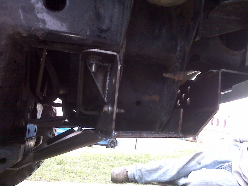
Today I finished up the latch for the receiver pin. Of course I needed something simple to operate, but simple to build so very little could go wrong with it. I thought the best solution was to make use of the offset between the two pieces of 5/8" rod... it works good enough to limit the throw, why not use the same concept? Below are the pieces for this unit. The rod is 1/4" with a half-washer welded to the side. The nut in the middle was actually drilled out and slid onto the rod, then welded in place as a stopper. After I finished, I threaded the left end of the rod with a 1/4-20 thread to screw on a black plastic knob. The angle-iron has a 1/4" hole in one side, and a threaded hole in the other side. The spring was just one I had in a bin that happened to be a perfect fit.
8715-img-7129.jpg


I used the angle grinder to cut a slot in the half-pipe, and the rod/washer assembly slides across this slot. As shown, the spring pushes the washer to block the slot, and prevent the hitch pin from sliding out of the receiver. There is a hole drilled through the front of the bumper which the rod slides through, and you can see how the welded nut stops the rod from sliding out too far. On the top side, the angle-iron supports the end of the rod. By unscrewing the angle-iron, the rest of the assembly can be removed.
8714-img-7133.jpg


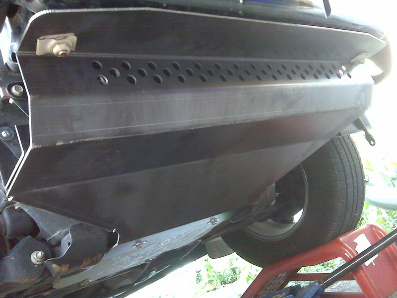
With the bumper back on the truck, you can see the black knob just below the license plate. It doesn't take much force to push it in, and only slides about 3/4 inch. You do need both hands free to unlatch the pin, but once the pin is pulled back, you can let go of everything and slide in the tool you need in the receiver. Sitting at a 45-degree angle you can see my makeshift handle. I just tapped another 1/4-20 hole through the end of the rod and stuck a bolt in it until I finish the bottom bevels and can see where my clearance is at. For now, you just push in the knob, slide back the pin, and insert a hitch. When you slide the pin back through the hitch, the spring on the latch pops it back in the locked position. Once everything is painted, I can grease up the slides to prevent rust and makes everything slide real smooth...
8713-img-7137.jpg


So that's about it for the mechanical bits. I still need to weld in plates to prevent the receiver from rotating up&down, but otherwise the receiver is completely functional now. Tomorrow I can get started cutting out the fog light holes, which will be all kinds of fun (the only tools I have for this are the angle grinder and files). Fabricating the cans for the fog lights should be fairly easy after all this!
 

Shdwdrgn

Original poster
Member
Dec 4, 2011
568
These fog lights are being more of a pain than I anticipated. I picked up some 1/8 x 4 inch steel yesterday to make the cans from... a little thicker than I was going for, but I won't have to worry about their strength. Unfortunately it's made it a bit harder to work the steel, so I spent all day hammering out the shape for the cans. It went a lot faster once I worked out that the best way to build these was to make the cans in two halves, then weld the pieces together after everything was just right. Once I get the back side finished, I'll cut down the front of each can to match the angle of the lights.
8772-fog-lights.jpg


I also got started on the back plate for each side. The hardest part is grinding out th hole for the plug. My largest drill bit is 3/4", and I need a hole closer to 1" in size. So between the dremmel and a file, I got the first side done and tacked to the can. Tomorrow I'll get that finished up, plus get the other side built. After that, I'll be using a strip of 1/2" wide bar to create a bevel around the front of each can, then I should be able to use that as a template to cut out the holes in the bumper and get the lights mounted up. I also want to find some heavy steel mesh to make guards for each light, slightly recessed into the bevels, to protect them from flying rocks.
 

Shdwdrgn

Original poster
Member
Dec 4, 2011
568
Yep, these fog lights are going to be a royal pain. Lots of work, for what looks like very little progress... but it IS progress. Oh, and I discovered today that the steel I got wasn't 1/8", but in fact 10ga. Minor difference, but it was still a lot of labor to get those first pieces rolled.

I picked up a hole saw today to cut a hole in the back plate for changing the light bulbs. After a LOT of work with a dremmel and files yesterday, I decided that simply wasn't going to work. You can still see the corners of the hole I filed out, but the hole saw cleaned up the area fairly nicely, and the other housing was done completely with the saw. Once I finished welding the back plate on, I cut a bevel across the bottom, similar to the factory bumper, to allow water to escape (or is it to keep the lights cooler?). Anyway, the lights fit good at this point...
8784-img-7144.jpg


Next I needed to cut a taper across the face of the cans so the lights would point straight ahead once welded to the bumper. What I forgot was that the front of my bumper vertically straight in front, so I ended up cutting more of a compound-angle than needed. Ah well, I can straighten it up again when I flatten out the top of the bevels.
8783-img-7145.jpg


I got started on the straight edges of the bevels, setting them all at a 45-degree angle. The curves will all have to be cut out - I will probably hammer a cone shape out of flat pieces, cut the bottoms and sides so each pieces fits a corner, then weld them in place. Once the top of the bevels are leveled out, I'll be ready to use each can as a template for cutting out the matching holes in the front of the bumper.
8782-img-7146.jpg


I'm done for the weekend, but hope to have my fogs functional again early next week...
 

Shdwdrgn

Original poster
Member
Dec 4, 2011
568
Wow these cans are taking a lot of time to build... I got the bevel finished on one can today. Tomorrow I'll get the other one done. The curves are quite a pain to make, but I think I've got my technique down pretty good now. I just start with a short piece of metal, hammer it around a piece of rod, then slightly flatten one side to make it more cone-shaped. Then its just a matter of cutting the sides and bottom so it'll fit in between the flat pieces. Weld, grind, polish, repeat.
8834-img-7149.jpg


Once the other side is finished, I will cut the top of the bevels to match the curve of the bumper. I'm on my last cut-off wheel (out of 20) for the angle grinder, though, so I may have to make a run to Harbor Freight before I can finish mounting the fog lights.
 

Shdwdrgn

Original poster
Member
Dec 4, 2011
568
Hooray for Harbor Freight! Today I picked up 20 more cutoff discs, a couple of 40-grit sanding discs for polishing, and a second angle grinder -- I get really tired of having to switch back and forth between grinding discs and cutoff discs all the time!

I finished up the second foglight can today, so tomorrow I'm ready to cut down the top of the bevels and cut out the holes in the bumper for the lights. I'll be really happy to get these finished, because building the fog lights has been the single most labor-intensive part of this entire build.
 

Bartonmd

Member
Nov 20, 2011
545
And that, ladies and gents, is why I don't do stock fog light mounting as an option... The lights aren't anywhere near good enough to make it worth the PITA of doing mounts for them, IMO.

But yes, I have 3 grinders. One has grindind disks on it, one has flap disks (what you should be using instead of flat sanding disks) on it, and the third one has a wire brush on it.

Mike
 

Shdwdrgn

Original poster
Member
Dec 4, 2011
568
I won't be able to finish the fog lights until tomorrow, which puts me at 6 days to get them built and mounted. Yeah it's definitely a labor of love, because if I had the choice, I doubt I'd do it this way again. On the other hand, I'll be the only one (foolish enough) to have factory fogs in an offroad bumper.

After spending a lot of the day finishing the prep work on the cans, I finally got them shaped and ready to install in the bumper. After transferring the pattern to the front, I got started cutting out the holes.
8911-img-7159.jpg


The drill nearly broke my body trying to cut out that larger hole, but I finally finished, and used the grinder to clean up the edges. I ran a weld all the way around the inside to make it solid and fill in any gaps, then ran a heavier bead around the front to completely fill the transition.
8910-img-7161.jpg


I fired up the grinder again and smoothed down the front welds, then cleaned it all up with a sanding disc, and finally, I have the first light finished...
8909-first-foglight-complete.jpg


Since all the prep work is done on the other can and the hole is marked out on the bumper, tomorrow I just have to cut the hole and weld the last can in place. I'm taking a huge chunk of metal out of the bumpers for these lights, but I think all the steel that goes back in should leave the bumper just as solid as before. Also the back side of the can is welded to the end of the top frame mounting plate, so it helps create extra strength against the corners twisting.

Ugh... one more day, then I'm taking a break!
 

Shdwdrgn

Original poster
Member
Dec 4, 2011
568
I keep looking at that last picture, and it absolutely amazes me that the profile for the top and bottom of the lights so perfectly matches the angles of the front of the bumper. That wasn't planned, but I'll take it! :wootwoot:
 

Sparky

Member
Dec 4, 2011
12,927
Told ya it would be so much easier to do round fogs :tongue:

Looks pretty good though, and neat that it lined up so well. Maybe it is just the pic but it looks like they are very deeply recessed. Camera trick? Or are they really well over 1" deep in the bumper?
 

Shdwdrgn

Original poster
Member
Dec 4, 2011
568
The outside edge is recessed about 1/2". The inside edge is recessed just a hair over an inch deep. I spent a lot of time making sure the back of the can was square to the vehicle so that the lights will still point straight forward, so the rest of the depth is simply the way they were designed. I'll try to get pictures from other angles, plus some shots from the back side tomorrow.
 

Shdwdrgn

Original poster
Member
Dec 4, 2011
568
This sudden jump of the temperatures back into the mid-90's is not helping matters! But I finally have the fogs installed...

First, a couple of shots of the back side showing how the foglight can ties into the top frame mount. It makes the corners pretty solid.
8927-img-7166.jpg


8930-img-7165.jpg


An image with the bumper mounted up again. I still need to finish grinding and cleaning up the inside of the light I just mounted today, but its about 99% complete.
8928-img-7167.jpg


And a view with the lights mounted up...
8929-img-7171.jpg


So the bumper currently weighs 92.2 pounds, including the shackles. I still need to weld in some vertical supports for the receiver. then it should be ready for use. Then I can add the underside bevels and some way to attach the fender-well plastic to the new bumper. It won't be much longer before I need to find a place to sand-blast the whole thing so I can paint it... but I'm taking a break for the rest of the week.
 

Sparky

Member
Dec 4, 2011
12,927
Are you going to paint it black, body color, or... ?
 

Shdwdrgn

Original poster
Member
Dec 4, 2011
568
Sparky said:
Are you going to paint it black, body color, or... ?

I'm going to color-match it to the body, but the shackles and new push-bar will be done in black. I discovered the local auto parts shops carry GMC indigo blue in a spray paint... If it matches up, it will make touch-ups a piece of cake.
 

Shdwdrgn

Original poster
Member
Dec 4, 2011
568
I finished cleaning up the fog lights today and got started on the underside bevel. Since I plan on making a skid plate to protect the radiator anyway, I wanted a recessed slot for the plate to sit in, so that it would sit flush to the bumper. This was an easy matter of overlapping two plates. After taking some measurements and checking where things were already protected, I decided on a 24" wide skid plate, and made the initial slot to match. Since these pieces were across the front of the bumper, they were nearly straight, so I went with the easiest method and just bought some 1.5" and 2" steel bar to create the overlap, finishing up with a piece 3" wide and a 1.5" lip left to bolt the skid plate to. This piece got welded to the underside of the bumper at a 45-degree angle, and sets the angle for the rest of the bevel as I finish it up.

While I had the bumper off, I got some templates drawn of the curve needed for the rest of the pieces. I plan on keeping the bevel 3" wide all the way around the underside, however it will be vertical on the sides, and rolled to 45 degrees across the front. Since working with these compound curves is such a pain, I decided to build the bevel in 5 separate pieces (2 on each side of the center section). These pieces will get cut out of the scrap of 3/16 I still have left over, and should make a huge difference in the effective strength of the bumper.

I did run into an issue while wrapping up today. My receiver is set to slide right under the cross-pipe between the front frame rails. This was initially positioned about 1/4" below the cross-pipe, but as I've added more pieces, the angle has changed just enough that today I had a lot of trouble getting the bumper back onto the truck. Next time I have it off, I'll use a clamp to try and push the receiver back where it belongs so I can get the vertical supports welded in place and keep the receiver from sitting directly against that pipe.

Oh, and I also got the side 'guides' cut off today, finally. They had in fact started to bend the fender pins just from diving around on the streets, so I can imagine those pins getting ripped off if I had tried going off-road. Problem solved now, but next time I have a moment, I still need to grind smooth the area where I had welded those brackets inside the bumper. Nothing shows, but there's still bits of sharp fresh-cut steel poking out, just looking for a hand to mangle...

Not much else to show until I get the bevel pieces cut out and start welding them in place... hopefully in the next couple days.
 

Shdwdrgn

Original poster
Member
Dec 4, 2011
568
I got the bevel pieces all cut out today, and got the bends formed in the first two pieces. The outside pieces are going to be a bit tricky, because not only do they get rolled, but they also get twisted. My arms are going to feel like jelly by the time I finish with them. I'm planning on yanking the bumper back off tomorrow morning, then spend a good deal of time welding. Over the next two days, I should be able to finish off the entire bumper, including the remaining internal supports.

I have a rather large chunk of plate steel left over from the 18x90 piece I cut the top pieces out of. I'm crossing my fingers that this might possibly be large enough to cut out the side plates for the new pushbar I will be building. I don't even have a pattern made up for that yet, but it appears there is enough length to lay both parts end-to-end. That will save me a good chunk of change as I move forward -- steel keeps getting more expensive!

And speaking of expenses, my running tally of receipts (materials only, not counting tools or supplies like MIG wire) currently stands at $295. Somewhere in there I managed to double my initial cost projection, not to mention kill off most of the Summer. Ah well, totally worth it! :cool:
 

Forum Statistics

Threads
23,332
Posts
638,006
Members
18,537
Latest member
moscoreli

Members Online

No members online now.