LED Mod Thread

Boricua SS

Member
Nov 20, 2011
3,080
Ohio
20130522_182423_zps500f4dbd.jpg

20130522_183601_zps0f767554.jpg

20130522_190457_zps0b374075.jpg

20130522_192223_zpsc056ea6b.jpg

20130522_192233_zpsebec7b85.jpg


:biggrin::biggrin::biggrin:
 
  • Like
Reactions: Sib and CaptainKD

ghenny440

Member
Dec 14, 2011
368
I purposely did the video during the day just to show how bright they really are
[video=youtube_share;QKYz7eHWSeE]http://youtu.be/QKYz7eHWSeE[/video]
http://img.tapatalk.com/d/13/05/25/sure5u
he.jpg
7y2u7a3y.jpg

7upuhe4u.jpg

yvetuqaq.jpg

ajeze4u9.jpg

Theres also white and purple but i dont like those colors so i snap a pic of them lol
 

ghenny440

Member
Dec 14, 2011
368
u3ysy6yj.jpg

This is the ambient lighting on the walls of boricua ss garage of my kit and this is a vid of the kit working with the sound activation
[video=youtube_share;uQZjvxE_CjA]http://youtu.be/uQZjvxE_CjA[/video]
 

ghenny440

Member
Dec 14, 2011
368
5agypese.jpg

qe6asu6a.jpg

Yeah i dont really have a visibility problem
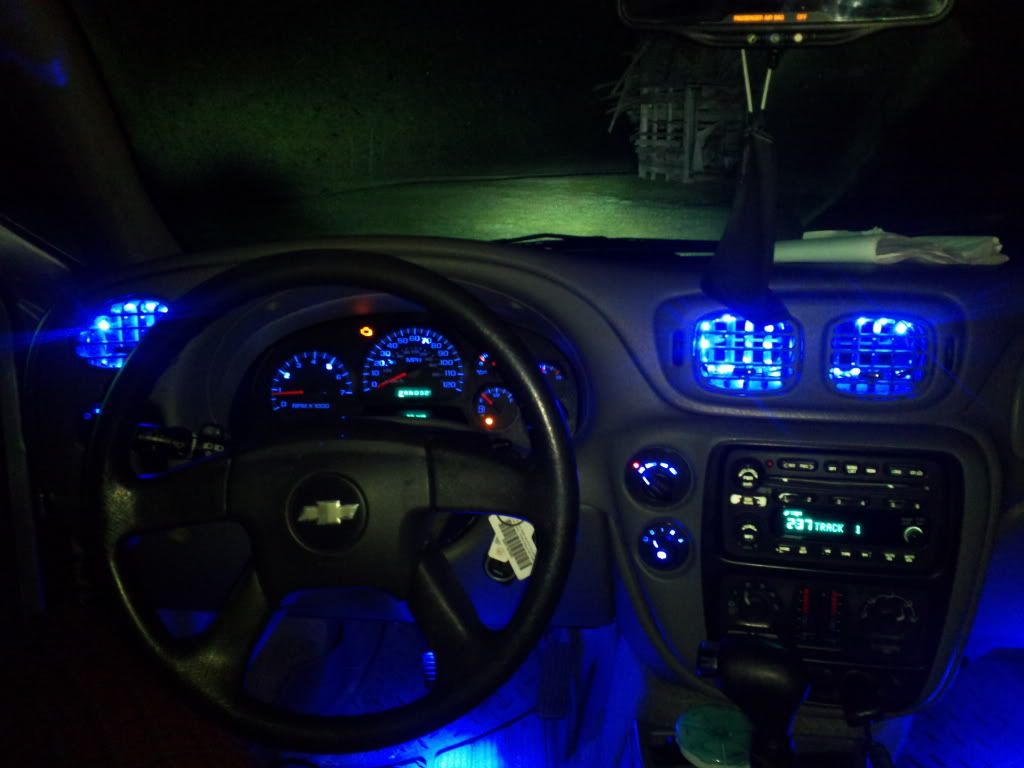
And the vent leds are on a seperate switch from the footwell leds just incase i did t want them on, but all that light is ambient light not direct light as the leds are placed at the top of the vents not the bottom so it is actually no brighter to the eye than the footwell leds
 

BINGA

Member
Jun 8, 2012
238
DDonnie said:
Not sure if you ever figured this out. If you have the ones in the center and not over the door, then you can remove the reflector and regain on/off push functionality.
Might you be referring to putting 194 LEDs in the overhead lights over the rear seats? I had that same problem with mine where i lost pushbutton functionality. Hmm...maybe this is the answer i was looking for...thanks!

Sidenote: anyone know if they make the dual LED 194s with, say, one white and one blue in each bulb? I had all blue ones in at one point but it was a little too blacklight-ty in my cabin...
 

DDonnie

Member
Mar 26, 2012
2,631
BINGA said:
Might you be referring to putting 194 LEDs in the overhead lights over the rear seats? I had that same problem with mine where i lost pushbutton functionality. Hmm...maybe this is the answer i was looking for...thanks!

Sidenote: anyone know if they make the dual LED 194s with, say, one white and one blue in each bulb? I had all blue ones in at one point but it was a little too blacklight-ty in my cabin...

Not sure about 194's i was referring to 48 smd panels. With the reflector in, you cannot press in on it, with the reflector out, you can :biggrin:


Here's today's mod

View attachment 28465
 

Attachments

  • 2013-05-28 20.49.09.jpg
    2013-05-28 20.49.09.jpg
    59.7 KB · Views: 16
  • Like
Reactions: Blckshdw

Blckshdw

Original poster
Moderator
Nov 20, 2011
10,776
Tampa Bay Area, FL
BINGA said:
Sidenote: anyone know if they make the dual LED 194s with, say, one white and one blue in each bulb? I had all blue ones in at one point but it was a little too blacklight-ty in my cabin...

If they made something like this, (I've only seen this done once, for the switchbacks) you'd have to rewire all of your dome light sockets. :twocents:
 

BINGA

Member
Jun 8, 2012
238
Blckshdw said:
If they made something like this, (I've only seen this done once, for the switchbacks) you'd have to rewire all of your dome light sockets. :twocents:

Curious. Why is that? Does the color of the LED matter?
 

Blckshdw

Original poster
Moderator
Nov 20, 2011
10,776
Tampa Bay Area, FL
BINGA said:
Curious. Why is that? Does the color of the LED matter?

194 bulbs have only 2 contacts on them. So to have 2 colors, and since LEDs are polarized (obviously they can't use the same +/-) they would have to be reversed from each other. The sockets in the dome lights have a specific power connection and ground, so the current only flows one way. In order for you to be able to change which direction the current flows, on command, you would have to do some rewiring to account for this.

yodaddy4200 said:
Hey guys i just noticed tonight that my tail lights arent working? My brake light lights come on so im guessing the bulbs are good. I visually checked a couple fuses and they looked good. I was wondering what to check next like a bad ground somewhere? Im really not sure where to look to fix this problem. I did some searching and didnt find much.

:nono: If Roadie hung out in this thread, he would probably post a Garfield comic at your expense for saying that. :raspberry:

:book: Troubleshooting 101 my friend. Get out your meter, and put it to work. If your brake lights work, then start at the parking light fuses and check each of them for power while the lights are on. If there's power at all of the fuses, when they should have power, unless you're quad modded, then go to the parking light socket and check for power there. It's a systematic approach, you just have to take your time and chase down your gremlins. :yes:
 

BINGA

Member
Jun 8, 2012
238
Just what does SRCK stand for anyways?
 

Short Bus

Member
Dec 2, 2011
1,906
BINGA said:
Just what does SRCK stand for anyways?

I don't know what it stands for, but here is a diagram that shows how to mod boards to non-SRCK and add quad tails (that should help with the difference).

Untitled.jpg
 

The_Roadie

Lifetime VIP Donor
Member
Nov 19, 2011
9,957
Portland, OR
BINGA said:
Just what does SRCK stand for anyways?
I've been annoyed by that question since the first time I saw the acronym. :hissyfit: :mad: :confused: Never bothered to research it until today,and I'm still not totally done.

The "CK" in the acronym seems to refer to the Chevy "C-K" series - full size pickups. Seems the electrical designer changed the assignment of the grounds in a way that incandescent lamps don't care, but it's backwards for LEDs.

More reading: Convert GMC CK Series To LED Tail Lights : How-To Articles

I also found sites that refer to "SACK" lamps as Amber, and "SRCK" as Red.

I haven't totally confirmed that the "S" means "Special", but that's my current prediction. "Special Red C-K".

Insane GM designers strike again, early and often.

View attachment 28490
 

Attachments

  • led-car-bulb-CK-wiring.jpg
    led-car-bulb-CK-wiring.jpg
    69.2 KB · Views: 141
  • Like
Reactions: CaptainKD

BINGA

Member
Jun 8, 2012
238
the roadie said:
I've been annoyed by that question since the first time I saw the acronym. :hissyfit: :mad: :confused: Never bothered to research it until today,and I'm still not totally done.

The "CK" in the acronym seems to refer to the Chevy "C-K" series - full size pickups. Seems the electrical designer changed the assignment of the grounds in a way that incandescent lamps don't care, but it's backwards for LEDs.

More reading: Convert GMC CK Series To LED Tail Lights : How-To Articles

I also found sites that refer to "SACK" lamps as Amber, and "SRCK" as Red.

I haven't totally confirmed that the "S" means "Special", but that's my current prediction. "Special Red C-K".

Insane GM designers strike again, early and often.

View attachment 14964

Thanks again roadie for shedding some light on the subject. So is it believed that GM is the only manufacturer that has adopted this "one-off" approach? I could think of many better ways to differentiate themselves from the pack...
:undecided:
 

NinjuhhNutz

Member
Oct 15, 2012
720
finished up the vent led's tonight :yes:
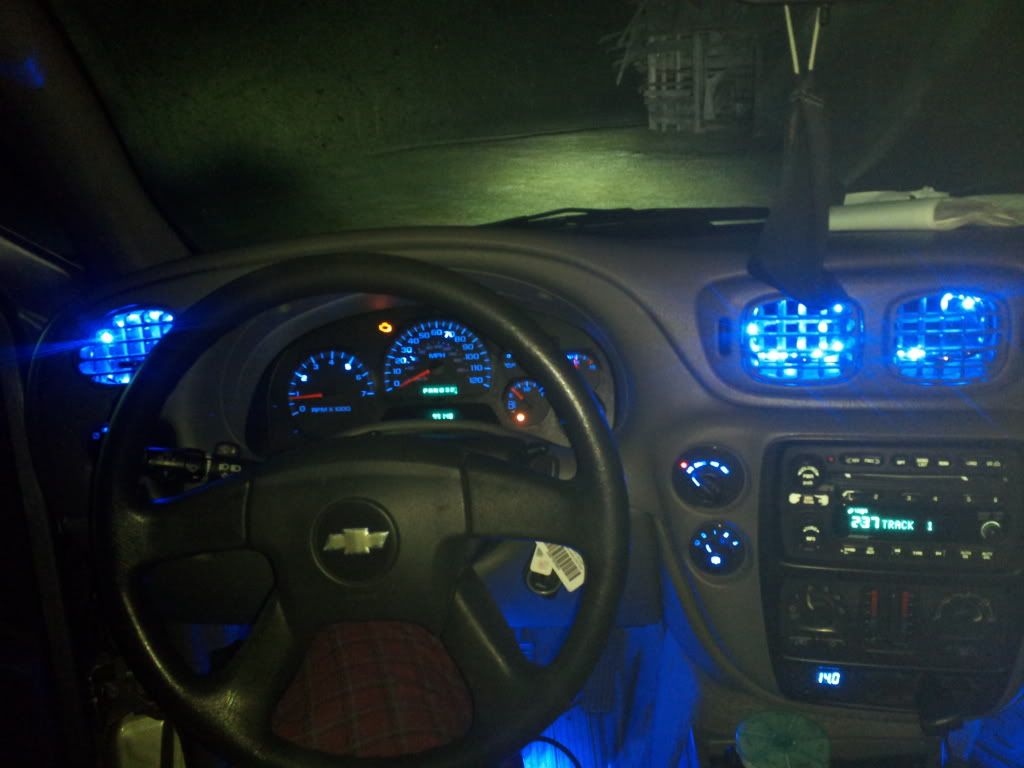
it's not EXACTLY how I wanted it to look, as I'm not all that happy about seeing the individual led's through the vents, but I like it anyways :raspberry:
considering how easy it was to install, I'm not complaining a bit
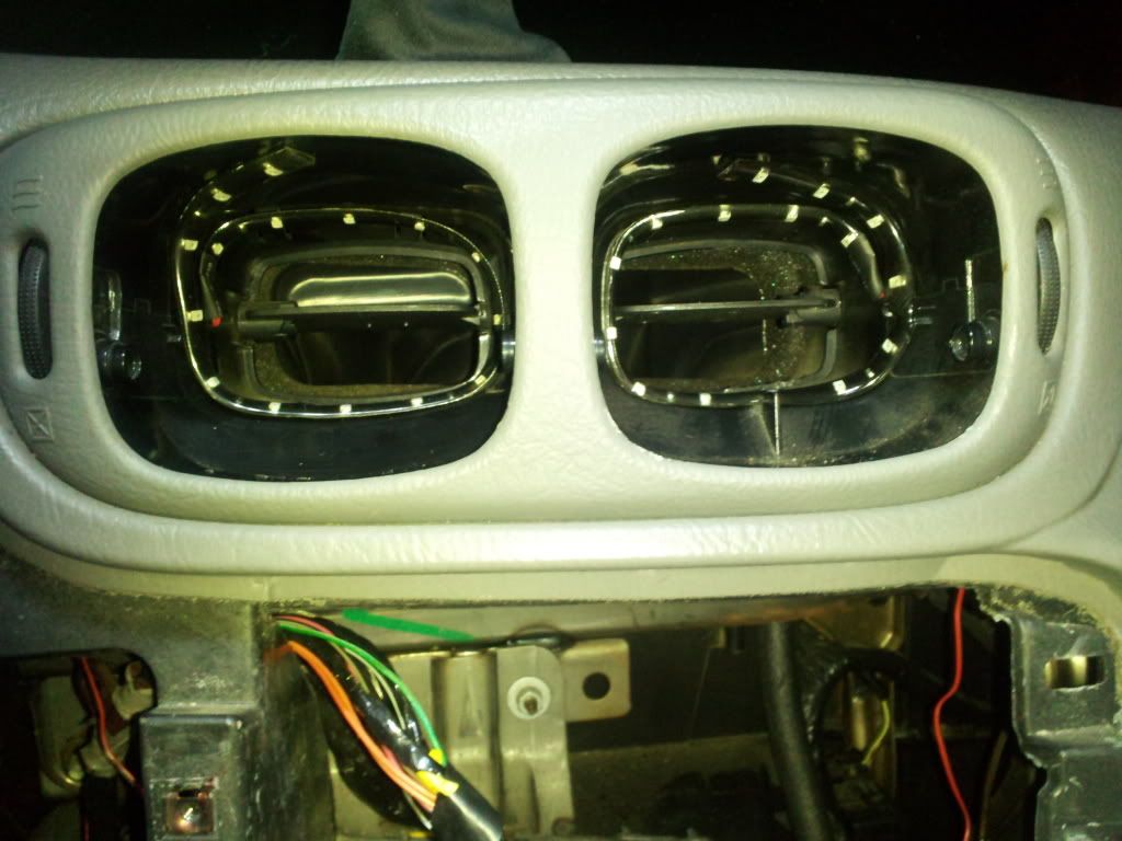
I didn't rip out the entire vent assembly, just popped a hole in each vent for the wires, took the head unit out, and fed the wires through. Tapped into the wiring for my footwell lights, and there she was!
2013-05-30023933.jpg
2013-05-30013655.jpg
2013-05-30024011.jpg
 
  • Like
Reactions: Blckshdw

DDonnie

Member
Mar 26, 2012
2,631

Attachments

  • led strips.jpg
    led strips.jpg
    52.6 KB · Views: 36

BINGA

Member
Jun 8, 2012
238
Blckshdw said:
If they were non polarized, then yes you could put them in either way and they should work. If flipping the bulb around solved the problem... You can guess the rest. :tongue:

So what kinda bulb are you looking for? One that can be blue OR white (switchback style), or one that has blue AND white active at the same time, so you get an 8000K-10000K sort of look? I've never seen this as a ready made bulb, but you can always make your own. :wink: Besides, if you made your own, you could determine just how much of each color you had, as they do not have an equal brightness when given the same amount of power.

The packaging was clearly marked "because these LED bulbs are non-polarized, they should work either way you plug them in". Oddly enough, they apparently only worked one-way. :confused: And to answer your question, the latter is the desired result. I really like the blue, but it could be overpowering and borderline blacklight looking, and not of much functional use when needing to turn the lights on for something dropped, reading something, etc.. So I emailed the company and inquired about such a product (the two blue and two white LEDs) and they replied that they did not have anything like that, but they do/will make custom bulbs on request and have forwarded to R&D. Guess I'll see what they come up with and how much they'll want for a custom product... :eyebrowhuh:

As far as making my own... I am on the bottom floor of that building, but I've been reading up and asking "vets", but I'm afraid once I start the bug will consume me whole. If/when I do though, my ultimate goal is to make a custom LED panel inside a stock taillight housing that has a perimeter of LEDs serving as brake/parks, surrounding a center of LEDs lit as turn signals. :salivate:
 

Blckshdw

Original poster
Moderator
Nov 20, 2011
10,776
Tampa Bay Area, FL
BINGA said:
The packaging was clearly marked "because these LED bulbs are non-polarized, they should work either way you plug them in". Oddly enough, they apparently only worked one-way. :confused: And to answer your question, the latter is the desired result. I really like the blue, but it could be overpowering and borderline blacklight looking, and not of much functional use when needing to turn the lights on for something dropped, reading something, etc.. So I emailed the company and inquired about such a product (the two blue and two white LEDs) and they replied that they did not have anything like that, but they do/will make custom bulbs on request and have forwarded to R&D. Guess I'll see what they come up with and how much they'll want for a custom product... :eyebrowhuh:

As far as making my own... I am on the bottom floor of that building, but I've been reading up and asking "vets", but I'm afraid once I start the bug will consume me whole. If/when I do though, my ultimate goal is to make a custom LED panel inside a stock taillight housing that has a perimeter of LEDs serving as brake/parks, surrounding a center of LEDs lit as turn signals. :salivate:

I understand what you mean about the blue bulbs not being bright enough to be useful for anything. That's how I felt when I got my 11 SMD bulbs back in the day. I can only imagine how dismal 4 LEDs would be :no: BUT, if 4 LEDs is all you want, then I would REALLY suggest making your own, and skipping some company that's probably going to overcharge for what it's worth.

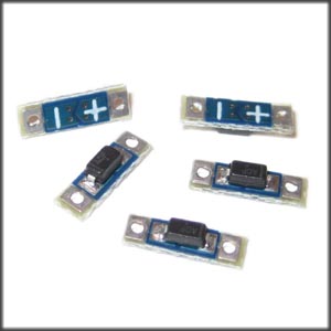
The approach I would take... Get some empty 194 bases, however many white/blue LEDs you'll need, and then either fiddle with resistors and resistor calculators, or grab a handful of those 20mA LED drivers that Ed posted for us a while back. All but the LED drivers can be found on Ebay for cheap. (LED driver pic is a clicky :cool:)

[EBAY]390604806396[/EBAY]
[EBAY]111069258609[/EBAY] [EBAY]121107315564[/EBAY]


Solder 2 white LEDs together in series, do the same with 2 blue ones. Connect the negative end of the LED driver to the positives on the white and blue LED sets together. You can use a piece of the trimmed LED leads to connect to the positive end of the LED driver, which gets fed through one opening in the 194 base, and bend it around locking it in place. The 2 negative ends of the LED sets come through the other opening in the bottom of the 194 base, and that's your ground. Put some silicone in the base to hold everything in place once it sets, and you're done. Easy peasy. :thumbsup:
 

mrphoenix80

Member
Jan 1, 2013
251
So my last... no scratch that.... latest mod I tried was to get my LED bulbs done for my stock tails. The ulitimate result....Failure. Let me explain.

I got some dorman boards for a trailblazer (by mistake) but figured it is the wiring that is different and I am changing that any way so I will be ok:thumbsup:. So I tore them apart. Added the terminals where needed to do the quad brake and tail lights. Got my schematics pulled up and rewired one board. Easy enough right???? So I grab my jump box and jumper leads and test each circuit and the board works just the way I want.
View attachment 28546

So I take my board with the LED bulbs in it to the truck and plugged it in. Did a light check and found that the brake lights are fine both bulbs on the left light up... great. Next the turn signal..... hyper flash ok I expect that I don't have a load resister in yet.. And now the tails.......nothing. Wait what???? So I go back and start looking and what do I see, SMOKE out of the bulbs! What the heck??? Take the board off the truck and go back inside and recheck it.. all ok :undecided: So I swapped out the LED bulbs with standard bulbs. Back to the truck. Perfect every thing works just fine. Did I get a bad LED bulb??? Well I got 7 sets cheap. So lets try again and..... more smoke!
OK so stock bulbs work ok but LEDs = smoke. So I pulled out the LEDs from the base and found that the brake and tail terminals are soldered together.
View attachment 28547
So back to the schematics! After some digging I find that the PCM is monitoring the brake light circuit for the cruise control. Over to the cruise schematic.. Oh look the PCM supplies a low level ground to the brake light circuit and watches for it to be pulled high when the brake lights are active. The Stock bulbs have the brake and tail totally seperate, but not the LEDs. So the LEDs create a loop, the tail light power comes in through the resistor in the bulb and right back out on the brake circuit to the PCM and to ground. That ground is too much for the little 1/8 watt resistors to handle and we get smoke. OK :mad: So if I put a diode in the brake light feed. That should open the loop and no more smoke:undecided: So off to the local Shack. Install a diode and back to the truck with the board... Success all the lights work as they should.:wootwoot:
Now to install the new board in the lamp and see how much better it looks....... WTF!!!!!!!!! The new board won't line up with the lamp. :banghead: Remember I said I got Trailblazer boards for the Envoy. They are a bit bigger:duh:
Oh and one more thing for me to think about did I effect my cruise by installing the diode??? I never got the boards installed so I can't test if the cruise still works or not. I think I will be ok because the PCM is tied in before the diodes(I Hope).
 

Attachments

  • IMG_0335.jpg
    IMG_0335.jpg
    45 KB · Views: 20
  • IMG_0340.JPG
    IMG_0340.JPG
    82.8 KB · Views: 156

BINGA

Member
Jun 8, 2012
238
Blckshdw said:
I understand what you mean about the blue bulbs not being bright enough to be useful for anything. That's how I felt when I got my 11 SMD bulbs back in the day. I can only imagine how dismal 4 LEDs would be :no: BUT, if 4 LEDs is all you want, then I would REALLY suggest making your own, and skipping some company that's probably going to overcharge for what it's worth.

The approach I would take... Get some empty 194 bases, however many white/blue LEDs you'll need, and then either fiddle with resistors and resistor calculators, or grab a handful of those 20mA LED drivers that Ed posted for us a while back. All but the LED drivers can be found on Ebay for cheap.


Solder 2 white LEDs together in series, do the same with 2 blue ones. Connect the negative end of the LED driver to the positives on the white and blue LED sets together. You can use a piece of the trimmed LED leads to connect to the positive end of the LED driver, which gets fed through one opening in the 194 base, and bend it around locking it in place. The 2 negative ends of the LED sets come through the other opening in the bottom of the 194 base, and that's your ground. Put some silicone in the base to hold everything in place once it sets, and you're done. Easy peasy. :thumbsup:

Once again...Carlton to the rescue! :thumbsup:
 

NinjuhhNutz

Member
Oct 15, 2012
720
Conner299 said:
The wiring I want to tap into is for the door jamb switches, as can be found on page 46 of the PDF.

are we looking at the same pdf? lol
I'm looking at the 2006 wiring pdf, and it shows the ground distribution circuits
I get the gist of the schematic reading...but when it's funky puhsketties like this, it gets a tad more difficult for me :hopeless:
I see that it ties into the harness in the headliner. So, is that a switched ground to signal the dome lights when the door is open? or am I just reading wayyyyy too much into it?

sorry...lol I thought about starting the puddle lights today before work, and against my better judgement, thought maybe I should figure out WHERE I'm wiring them, before I start :rotfl:
 

Conner299

Member
Jan 16, 2013
279
NinjuhhNutz said:
are we looking at the same pdf? lol
I'm looking at the 2006 wiring pdf, and it shows the ground distribution circuits
I get the gist of the schematic reading...but when it's funky puhsketties like this, it gets a tad more difficult for me :hopeless:
I see that it ties into the harness in the headliner. So, is that a switched ground to signal the dome lights when the door is open? or am I just reading wayyyyy too much into it?

sorry...lol I thought about starting the puddle lights today before work, and against my better judgement, thought maybe I should figure out WHERE I'm wiring them, before I start :rotfl:

I think I was actually looking at the PDF for the 2004 year... And that was my original plan. Then jimmyjam put up his post(#1004) on page 34, and talked about the right way, I guess, to tie into the wiring for the door control modules. Haven't had time to work on it, and was still a little foggy on it, even with jimmyjams explanation in that post. I was actually going to send him a pm, professing my electrical ignorance and asking of the possibilty of posting up a wiring diagram, including my relays, for this mod.
 

mrphoenix80

Member
Jan 1, 2013
251
When I did my puddle light/ logo projectors I tied in to the door module battery+ and the door latch switch right at the back of the door module. No relays, No fancy running wire into to the door from the "B" piler.

So the wires I used.....
Left Front
View attachment 28647
Right Front
View attachment 28648
Orange is 12v battery power and the other goes out to the door ajar switch in the latch and to ground. I still have normal functions like dome lights and everything. I do need to redo the drivers door wiring as you can see the leads from the projector I got are very tiny so I had a very hard time getting it to stay in any connector. I soldered bigger leads onto the one for the passenger door.
 

Attachments

  • IMG_0347.JPG
    IMG_0347.JPG
    75.1 KB · Views: 150
  • IMG_0349.JPG
    IMG_0349.JPG
    76.2 KB · Views: 148
  • Like
Reactions: CaptainKD

NinjuhhNutz

Member
Oct 15, 2012
720
done the drivers door when I got home from work a few minutes ago...not as bright as I wanted, may end up doubling up the cheap led strips I have :undecided:
not bad for 10 minutes lol

2013-06-06004104.jpg


any output pics of how the individual led's look? I'm sure they're brighter :yes:
 
  • Like
Reactions: CaptainKD

dmanns67

Member
Apr 3, 2013
32,979
Ohio
Here are some good informational videos that can assist in the understanding of LEDs and their components.

Ohms:

[VIDEO=youtube;-mHLvtGjum4]http://www.youtube.com/watch?v=-mHLvtGjum4[/VIDEO]

How to use a digital multimeter: Nearly as critical as a soldering iron.

[VIDEO=youtube;BW3Wj7UD-_s]http://www.youtube.com/watch?v=BW3Wj7UD-_s[/VIDEO]

How diodes work:

[VIDEO=youtube;AqzYsuTRVRc]http://www.youtube.com/watch?v=AqzYsuTRVRc[/VIDEO]

Resistors:

[VIDEO=youtube;VPVoY1QROMg]http://www.youtube.com/watch?v=VPVoY1QROMg[/VIDEO]

Capacitors:

[VIDEO=youtube;ZYH9dGl4gUE]http://www.youtube.com/watch?v=ZYH9dGl4gUE[/VIDEO]

Heres another one for you History buffs:

[VIDEO=youtube;P3PDLsJQcGI]http://www.youtube.com/watch?v=P3PDLsJQcGI[/VIDEO]
 
  • Like
Reactions: Sib and CaptainKD

DDonnie

Member
Mar 26, 2012
2,631
wesman43 said:
Haha, yes. I know what a relay is, but I don't know differences or anything special, nor do I know what a relay with more than 3 prongs does lmao

quick n dirty

View attachment 15229
 

Attachments

  • on with domes.JPG
    on with domes.JPG
    36.1 KB · Views: 22

Blckshdw

Original poster
Moderator
Nov 20, 2011
10,776
Tampa Bay Area, FL
Decided to do some LED maintenance today. After I put the white LEDs in my HVAC behind the sliders, less than a week later, one of them went out :hissyfit: When I tested it, it was just dead, so had to solder in a fresh one.
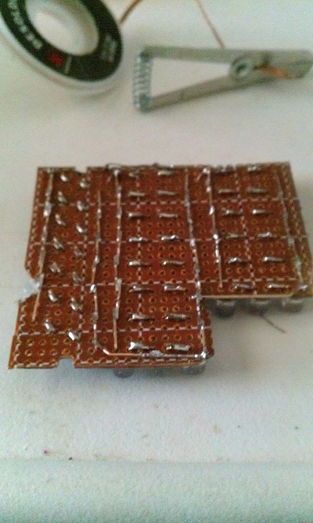
My homelink has an LED with a broken solder joint. When it's cold outside, the LED lights, as it warms up during the drive, it will flicker, and then go out. Also had a section of 3 LEDs in each front dome light that had issues. Those were a pain to get out. Once I got the console down, I realize that I gave my toolset that has a torx head small enough for the homelink screws, to a friend of mine, who now put that in storage, so that fix will have to wait a while longer :duh:

On to the dome lights, one of the LEDs went bad, causing the 2 in series behind it to not light. Desoldered that, popped a new one in, and operation blue sunlight is again a success. I know people wanted to see the back side of my boards before, so here's a shot I took.

IMAG0657_zps20a3f6d4.jpg


While I had the console down, decided to run my HU mic up the A pillar, and to the console opening, so it's tucked away but still usable. Haven't tested that yet. Shitty part is, when I put everything back in and hit the dome override button, a different section of 3 LEDs went out. :banghead:

I did NOT feel like messing with that again, so just left it how it was. If anyone looks at it long enough to notice, they'll be temporarily blinded anyway :satan:
 

Conner299

Member
Jan 16, 2013
279
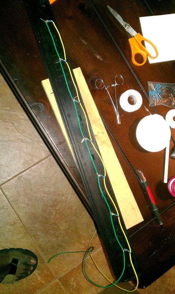
Well, I finally got my puddle lights completely wired up. I was hoping to have a grand reveal, on here, later tonight. Alas... Tis not to be... Everything is all wired up, and is getting power. I have twenty lights on each door, and the only ones firing are the first one and a half, which are the ones closest to the power. They light up when the door opens, and turn off when closed, as they should. Each door behaves indentically. I think I used too many resistors, or wrongly rated ones. But even then, why wouldn't all the lights fire up dimly, instead of just the first couple. I'm stumped and looking for help, and even better, answers. Any advice is, as always, greatly appreciated.

Here's the current problem


For removal of the door panel, I spliced in a couple of butt-end plug connectors. I also remembered to marker the heck out of both sides of the negative connectors.


They are all soldered up with positives down one side, negatives with resistors down the other side. All connections were triple-checked, and only positive is touching positive, and negative is touching negative.
 
  • Like
Reactions: Blckshdw

Blckshdw

Original poster
Moderator
Nov 20, 2011
10,776
Tampa Bay Area, FL
Conner299 said:
...I have twenty lights on each door, and the only ones firing are the first one and a half, which are the ones closest to the power. They light up when the door opens, and turn off when closed, as they should. Each door behaves indentically. I think I used too many resistors, or wrongly rated ones. But even then, why wouldn't all the lights fire up dimly, instead of just the first couple. I'm stumped and looking for help, and even better, answers. Any advice is, as always, greatly appreciated.

Here's the current problem


They are all soldered up with positives down one side, negatives with resistors down the other side. All connections were triple-checked, and only positive is touching positive, and negative is touching negative.

They are wired up incorrectly. If you are going to use a 1 to 1 setup with the LEDs and resistors, the resistor needs to be between the LED and the 'group' ground. This way the current passes through each single LED and resistor individually, hits the ground, and finishes the circuit. The way you have it, the current passes through all of the LEDs just fine, but the resistors are adding up the further you get from the source. So the first LED sees 1 resistor, as planned, and lights up brightly. The 2nd LED sees 2 resistors, and is much dimmer as a result. The next sees 3 resistors, and doesn't have enough power to overcome it, and so on...

Here's the backside of my scuff plate, which is wired up the way you're intending.

IMAG0132_2.jpg
 

Conner299

Member
Jan 16, 2013
279
Blckshdw said:
They are wired up incorrectly. If you are going to use a 1 to 1 setup with the LEDs and resistors, the resistor needs to be between the LED and the 'group' ground. This way the current passes through each single LED and resistor individually, hits the ground, and finishes the circuit.

IMG_20130608_214844_zpsdc96e8f7.jpg


So, I'm basically wired up as in the example labelled "1". This is no bueno. I basically need to run a wire the entire length of my LED's, and connect the resistors to that wire, as in example "2"? Once again, Carlton, you are THE MAN!
 

Blckshdw

Original poster
Moderator
Nov 20, 2011
10,776
Tampa Bay Area, FL
Conner299 said:
So, I'm basically wired up as in the example labelled "1". This is no bueno. I basically need to run a wire the entire length of my LED's, and connect the resistors to that wire, as in example "2"? Once again, Carlton, you are THE MAN!

Yep, that sums it up. Hope it doesn't take you too long to fix.
 

Conner299

Member
Jan 16, 2013
279
Ohhh... I figure it will be a good 4-6 hours of work :lipsrsealed: :suicide: :lipsrsealed:, at least... But, I'll just throw on the Sirius, and get into my own little world. I just wish SOMEONE, *hint,hint*, would've told me this when I put up my first posts(page 34) on this mod, a week or so ago. *cough*Carlton*cough*! :raspberry: I'm a pro at taking the door panels off, and putting them on, by now, too. 5 or 6 times, at least. The biggest thing is making sure the lips at the top of the panel and door hook each other. Otherwise, the bezel for the door handle wants to keep popping out!
 

Conner299

Member
Jan 16, 2013
279
I went outside for a smoke break, and decided to check out the light output, for even just the one and a half working LED's. It's gonna be HOT! The only problem I have, and it has me rethinking my fix, is the fact the puddle lights are "warm white" LED's. They basically look like factory dome lights. My gauges and switches have all been replaced with blue LED's. The dome lights have been changed to "corn cob" style smd's, 194 bulb LED's, in bright or cold white. I think the puddle lights in "warm white", will just look goofy. They won't match the domes:no:! I think it'll look better if the domes and puddles match. Two colors of LED's, compared to three. I'm already going to have to unsolder, and resolder 40 joints, just to fix what I have already done. I'm thinking, now, it might be easier to rip out and redo, what I've already done, with the right LED's. Opinions...

I really wanted to be the first one to do this mod, in this fashion. If my screw-ups can help someone else, then so be it. I'll share a few a tips, if you go about it my way. 1) Use a drill bit that is just a tad bit smaller than the head of your LED. Then, gradually open up the hole with a needle file, until the LED is practically a press fit into the hole. I did this on my passenger panel, and it worked perfectly. I did the driver door first, rather hastily, and required more hot glue to keep LED's immobile, cause I didn't do this. 2) When I mount the LED into it's hole, I barely put it in at first. I then put a little bit of hot glue on each side of the head. With a pair of needle nose pliers, I finish pressing the LED into place. 3) If you are mounting LED's directly into original truck plastic, mount them no more than an inch apart. I lucked out with this distance. Anything more, you will need a jumper wire between terminals. If you plan on spacing them far apart, you'll need one anyways. 4) Use butt-end connectors, if you plan on installing LED's into plastic body panels. Also, wire up with enough slack to be able to remove the panel and disconnect the wire(s). This will make removing body panels, for service, easy. You also won't have to worry about over stretching wire, and messing up connections. 5) If you use butt-end connectors, MAKE SURE YOU LABEL POSITIVE AND NEGATIVE CONNECTIONS. This is done easily with a Sharpie. All you have to do is mark both connectors for the negative side, VERY NOTICEABLY. I hope this helps...
 

ghenny440

Member
Dec 14, 2011
368
uva8e8a9.jpg

nahatu3y.jpg

Here is a mercedes bens i have been working on at my job, i just finished these yesterday, and the fiberglass dash is out to paint now
 
  • Like
Reactions: Blckshdw

Blckshdw

Original poster
Moderator
Nov 20, 2011
10,776
Tampa Bay Area, FL
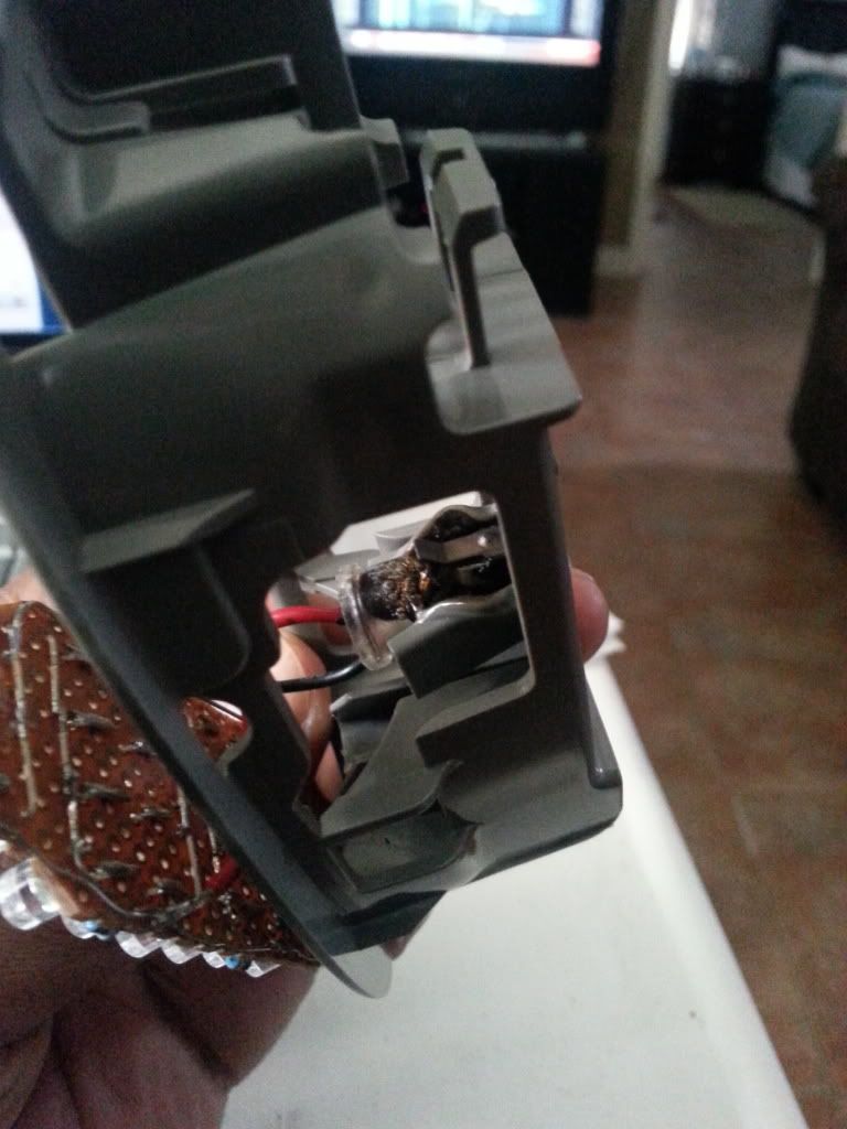
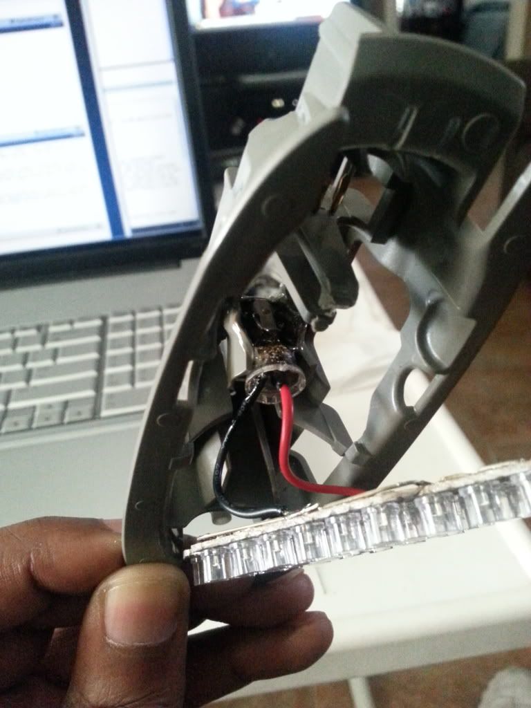
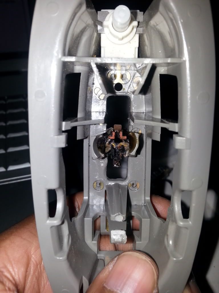
Did some quick and slightly questionable troubleshooting to figure out why my dome light fuse kept popping. I thought it was an issue with the section I took out to fix (and screwed something up)

I put in a 15 amp fuse, in place of the expected 10 and sat for a second to watch them. The fronts didn't light up at all. 2nd row domes flickered, or were dim, and then after about 10 seconds, plumes of smoke started coming from one of the 3rd row seat dome lights. Shut them off and went to look. Looks like there was a problem in the base that caused a short, and now it's melted together to the deformed dome light assembly. No idea how that happened, as they'd been fine for over a year, and they haven't been touched since the original install. :ugh:

The base of the dome light assembly is a bit deformed, so next time I'm at a junk yard, I'll be keeping an eye out.

20130621_171437_zps90d80063.jpg


20130621_171334_zps21832074.jpg


20130621_173647_zps7f86951e.jpg
 

yodaddy4200

Member
Feb 3, 2013
350
yodaddy4200 said:
Well the pos GP thunder bulbs i got didnt work. Well one did but the other wouldn't signal. Yes i flipped it over did all kinds of stuff and it just wouldn't work.

So i went on ebay and picked these up... 3157 3457 3057 4157 High Power LED Switchback Turn Signal Lights

I hope these bad boys are bright enough during the day without the 12 50/50 smd's around the base:confused: If these dont work im going to Autolumination.com and gonna fork out the $70 for the ones i want from them.


Well here they are... They work perfect!! It was kinda sunny when i took the pick but they should be bright enough during the day i think:confused:

View attachment 29046

View attachment 29047
 

Attachments

  • P1000885.jpg
    P1000885.jpg
    90.9 KB · Views: 43
  • P1000886.jpg
    P1000886.jpg
    77.1 KB · Views: 42
  • Like
Reactions: Sib and CaptainKD

ChevyTBLover

Member
Nov 21, 2011
116
I've got something in the works :smile:
 
  • Like
Reactions: Blckshdw

Forum Statistics

Threads
23,746
Posts
642,870
Members
19,318
Latest member
soRadJad

Members Online