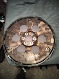
So Ive had my 2001 Silverado for a couple years now((2001, 5.3 liter, LM7, Extended Cab ,LS , RWD), and about two months go, she threw a rod. After weighing my options I decided to find a used engine and swap it out myself. After about a months time of searching I found a gentleman online that was parting out his 2000 extended cab and along with it his 5.3 liter Vortec which ( I believe) was on a 4WD drivetrain. After extensively cleaning it and doing some other essentials (rear main seal, front seal, all gaskets and refurbished 862 heads) , I am finally ready to drop it in. But I seem to be running into some issues. Im doing all this pretty much by myself , but last night I had a family friend come through to help me mate the engine to my existing 4l60e, and after much nudging and cajoling, and even trying to "guide" the two surfaces together using some long bolts ran through the engine-to-transmission bolt holes, the friend gave up, saying hes done a few engine swaps, and hes never had one not just "come together" when the two devices were brought together. The friend says he has doubts as to the torque converter alignment in relation to the flywheel, and/or its compatibility with the donor engine. My question is this: Does anyone here know of any modifications required to make this swap succesful? Am i doing something wrong? Is there something im missing? The flywheel appears to have been installed correctly( convex going towards the transmission) , or do i simply need to keep shimmying and nudgin the old girl home? I hope the informatioin ive provided is helpful, sorry for the novel, and as always thanks so much for anyones feedback and insight......im so tired of not having my baby driveable....please help :/
You are using an out of date browser. It may not display this or other websites correctly.
You should upgrade or use an alternative browser.
You should upgrade or use an alternative browser.
Engine Swapping Made Un-Easy
- Thread starter jakster918
- Start date

They did change the flex-plate design at some point, specifically at the pilot. My suggestion would be to swap the flex plate from your blown motor over to your donor motor, and try again.
Thank you, and do you share the same opinion , that when using the correct flex plate, that pretty much the tranny and engine should more intuitively come together? We are using fly wheel and flex plate interchangeably here right? ( im probably using the wrong term lol)They did change the flex-plate design at some point, specifically at the pilot. My suggestion would be to swap the flex plate from your blown motor over to your donor motor, and try again.
And actually, as im sitting here thinking.......i salvaged as much of the old 5.3 as i could(cleaned the sh** outta the intake manifold, altenator, water pump etc...) some of the parts were unusable due to engine sludge ......but the fly wheel, the fly wheel i destinctly recall soaking it in rust remover and then mounting it to the donor engine. So unless the flexplate refers to something not fly wheel, then i am in fact using the one from the blown engine.


This is the only area of concern.. Hopefully you still have the old engine for comparison..

@movietvet , Is my thought process here correct?
The only other thing I can think of is a alignment dowel being stuck in the donor engine block.
The only other thing I can think of is a alignment dowel being stuck in the donor engine block.
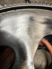
Is there not markings on each flexplate that identify "engine" side and "transmission" side?
When you look up the crankshaft, flexplate and transmissions, for the 2 years, they are the same.
OP, just for future reference, flexplate=auto transmission, flywheel=manual transmission.
If mounting holes alignment and dowels are the same and flexplate is mounted correctly, this mating should slide together. Hold your tongue "just right" and it should go fine, that works for me.
Sorry for the late update, and ty both for the help, i also appreciate the flexplate vs. flywheel clarification, "the more you know" right? So when we last left off, i went outside to check the flexplate and that was tuesday, so i went out, hoisted it up, and really felt kind of inconclusive. So then i thought well ill just remove the wheel and verify it says "engine side " on the side i had in, so of course, while doing that i stripped the head on one of the flexplate bolts as well as giving my self a pretty gnarly gash on my hand, yada yada easy out later, i got bolt out , and turned the wheel over to find.........of course nothing. So. then i thought well all things being equal, im gonna and mout the engine, as the tranny is now on a proper transmission jack......took all day today to do that so, now(with according to reports iminent snow coming) i have the motor mounted , tomorrow i will be reinstalling the flexplate but honestly it (the flexplate) seems to have been mounted correctly, before i came in tonight i did kind of a dry run and pushed the tranny right up to the inlet on the engine and honestly, i think its like @movietvet said and that its just going to need a little love going. So im gonna try again tomorrow and just see if it will be easier moving a less than 500lb device around on a jack instead of an almost 1000lb one from a chain, ill update on results but hopefully it will be a short one saying thanks and got er done.......thanks again yall
oh and when you say mounting holes u are just referring to the holes in the rear of the block and pan where the tranny hardware (studs etc) bolt in, right?Is there not markings on each flexplate that identify "engine" side and "transmission" side?
When you look up the crankshaft, flexplate and transmissions, for the 2 years, they are the same.
OP, just for future reference, flexplate=auto transmission, flywheel=manual transmission.
If mounting holes alignment and dowels are the same and flexplate is mounted correctly, this mating should slide together. Hold your tongue "just right" and it should go fine, that works for me.
Two observations:
(1) Following 'The *Clunk-Clunk* Principle" whenever "Sliding &Turning" the Torque Converter into the Body of the 4L60E Transmission Fluid Pump... it is possible to fail to insert the TC in FAR Enough and thereby, prevent the Bell Housing of the 4L60 Transmission from mating easily with the back of the LS Engine Block. If you do not get that *Clunk-Clunk* sensation...then the TC might then become the Obstruction if it is NOT completely seated.
(2) It has happened in the past that whenever a Mechanic fails to examine the Alignment Pins on BOTH SIDES in between the Bell Housing AND The Engine Block... thus, it is possible to MISS seeing that there might be Two Alignment Pins... directly opposing each other in their Mirrored Positions.
Last edited:
Good call @mrrsm on the torque converter not being seated "back" in to the transmission before engine and transmission mating. As you look from front to back, turn the torque converter clockwise and push back at same time and the torque converter should "drop back" in two stages and then still spin. That is important to protect the front pump of transmission and make room.
The mating of the transmission and engine should be as close to parallel as possible. Touching on one side/area and "clamshelling" the rest, typically does not work. Too much of a fight. Use the right tool, transmission jack" for the right job.
The mating of the transmission and engine should be as close to parallel as possible. Touching on one side/area and "clamshelling" the rest, typically does not work. Too much of a fight. Use the right tool, transmission jack" for the right job.
Excellent stuff, ty for that!Two observations:
(1) Following 'The *Clunk-Clunk* Principle" whenever sliding the Torque Converter into the Body of the 4L60E Transmission Fluid Pump... it is possible to fail to insert the TC in FAR Enough and thereby, prevent the Bell Housing of the 4L60 Transmission from mating easily with the back of the LS Engine Block. If you do not get that *Clunk-Clunk* sensation...then the TC might then become the Obstruction if it is NOT completely seated.
(2) It has happened in the past that whenever a Mechanic fails to examine the Alignment Pins on BOTH SIDES in between the Bell Housing AND The Engine Block... thus, it is possible to MISS seeing that there might be Two Alignment Pins... directly opposing each other in their Mirrored Positions.
View attachment 111037
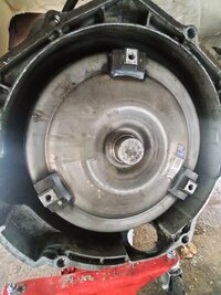
If you look at it, like in the pic, and spin it to the right, clockwise, and push at same time and do 2 complete revolutions, it should be back all the way and then it can still slide forward, so be careful when lining up.Under the truck now, the tc seems seated , here's a photo
Use one of these tools to hold it. May be able to rent it at parts store.Oh , one last thing, any suggestions for keeping this wheel from turning while I torque these bolts for the flex plate in?
They are not expensive and can be had for cheap and is nice to have if ever need to turn while in the vehicle.


Last edited:
Here's a photo I took just now of rear of engineI'm sorry I missed i ital req for crankshaft photo, I will send when back at the house
Attachments
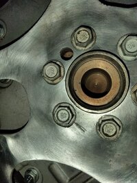
So your question.. and you will have to get a measuring tape, or micrometer to be sure.. Is the hole in the center here...

Big Enough to accept the nub in the end of the torque converter here..

Visually speaking, based upon what I can see in the pics... It should be.. But only one way to be sure.
Big Enough to accept the nub in the end of the torque converter here..
Visually speaking, based upon what I can see in the pics... It should be.. But only one way to be sure.
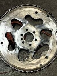
Hmmm...  Well... Given that the name "Flex-Plate" implies "Flexing" due to the hunting forces imparted at the Tail End of the Crankshaft with STRONG Fore & Aft Motions present during the Normal Rise and Fall of Engine RPM and Torque... Flex-Plates Really DO "FLEX":
But... because of the NEW Damage done to the area adjacent to that "Boogered Bolt Extraction".... you now have to be considerate about possibly inducing a Fracture Cascade that can eventually break out the entire Center Bolt Up Area in the circumference around that Old Flex Plate Center.


These Flex Plates are ubiquitous on Amazon and fairly inexpensive as shown by this Generic Chinese Example. The GM OEM Version would, of course be the Better Choice:

Now... I'm a fairly "Conservative Mechanic" ... But I am NOT "Nostradamus" or "The Amazing Kreskin" when it comes to accurately Predicting Inevitable Mechanical Failure. However, given how much "Bravo Sierra" you have had to contend with so far on this Accursed Engine Swap...Why Tempt "The Fates" only to have this Round, Toothy Platter wind up "Putting The BITE On YOU"...?
Right now... You have "The Gift of a Disassembled Engine to Transmission" event that you would be well advised to take advantage of... even if it means re-doing this work a Third Time. One Last Observation... It is NEVER a Good Idea to use the application of a Heavy Wire Wheel over a Large Surface Area of Thin Mild Steel as it tends to make the Surface Areas underneath there Work Hardened... and VERY BRITTLE.
Well... Given that the name "Flex-Plate" implies "Flexing" due to the hunting forces imparted at the Tail End of the Crankshaft with STRONG Fore & Aft Motions present during the Normal Rise and Fall of Engine RPM and Torque... Flex-Plates Really DO "FLEX":But... because of the NEW Damage done to the area adjacent to that "Boogered Bolt Extraction".... you now have to be considerate about possibly inducing a Fracture Cascade that can eventually break out the entire Center Bolt Up Area in the circumference around that Old Flex Plate Center.
These Flex Plates are ubiquitous on Amazon and fairly inexpensive as shown by this Generic Chinese Example. The GM OEM Version would, of course be the Better Choice:
Now... I'm a fairly "Conservative Mechanic" ... But I am NOT "Nostradamus" or "The Amazing Kreskin" when it comes to accurately Predicting Inevitable Mechanical Failure. However, given how much "Bravo Sierra" you have had to contend with so far on this Accursed Engine Swap...Why Tempt "The Fates" only to have this Round, Toothy Platter wind up "Putting The BITE On YOU"...?
Right now... You have "The Gift of a Disassembled Engine to Transmission" event that you would be well advised to take advantage of... even if it means re-doing this work a Third Time. One Last Observation... It is NEVER a Good Idea to use the application of a Heavy Wire Wheel over a Large Surface Area of Thin Mild Steel as it tends to make the Surface Areas underneath there Work Hardened... and VERY BRITTLE.
Last edited:
JayArr
Member
I'll wait for confirmation from the OP but the end of that crank looks like it's too small for the Torque converter end nub. That looks like the kind of brass bushing I've seen in the end of a crank used with a manual transmission.
My $5 bet is on that bushing having to come out.
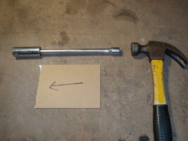
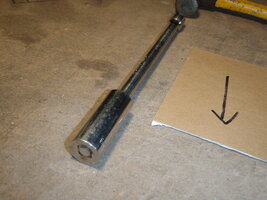
Removal is as follows:
Pump any kind of grease you have lying around to fill the hole almost all the way up. It will be your hydraulic fluid.
You want to make a 'plunger' so take a socket that will fit just inside the bushing and put an extension in through it backwards so you have a flat surface to push the grease with. Insert into the hole and hit extension with hammer. The force will go into the grease but due to hydraulics it will reverse direction and push on the backside of the bushing forcing it out.
My $5 bet is on that bushing having to come out.
Removal is as follows:
Pump any kind of grease you have lying around to fill the hole almost all the way up. It will be your hydraulic fluid.
You want to make a 'plunger' so take a socket that will fit just inside the bushing and put an extension in through it backwards so you have a flat surface to push the grease with. Insert into the hole and hit extension with hammer. The force will go into the grease but due to hydraulics it will reverse direction and push on the backside of the bushing forcing it out.
Attachments
And for those with Engine Stand Mounted Motors... an Alternative Tool for Pilot Bearing R&R with Clutch & Heavy Flywheel Applications... with an unfortunate reputation for being very difficult to use:
Last edited:
Mooseman
Moderator
Good call. I could not "see the forest for the trees". Sure looks like there is a bushing/bearing in there and that clearance should always be bigger than what we see there, anyway.I'll wait for confirmation from the OP but the end of that crank looks like it's too small for the Torque converter end nub. That looks like the kind of brass bushing I've seen in the end of a crank used with a manual transmission.
My $5 bet is on that bushing having to come out.
Removal is as follows:
Pump any kind of grease you have lying around to fill the hole almost all the way up. It will be your hydraulic fluid.
You want to make a 'plunger' so take a socket that will fit just inside the bushing and put an extension in through it backwards so you have a flat surface to push the grease with. Insert into the hole and hit extension with hammer. The force will go into the grease but due to hydraulics it will reverse direction and push on the backside of the bushing forcing it out.