Welcome back, Matt…
Let’s “Eat this Elephant” One Bite at a Time:
Major GM Atlas 4.2L LL8 Engine Fasteners and Gaskets:
...via my "Flickr-Bucket" images with Parts, Part Numbers and Box-Bag Markings:
These Images include the Major TTY Engines Fasteners and Gasket Sets for the GM Atlas 4.2L In Line Six Cylinder Engine.

www.flickr.com
Additional Components and Part Numbers:
New Genuine GM 24100263 Engine Camshaft Bolt
New Genuine GM 12565425 Bolt
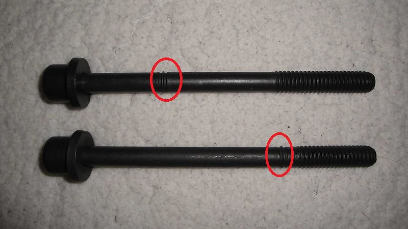
Fel-Pro ES 72195 Cylinder Head Bolt Set
Fel-Pro Hs26214Pt Head Gasket Set
AC-Delco 15-11073 GM Original Equipment Engine Coolant Thermostat Housing
GMC O2 Oxygen Sensor SG1823 15894 234-4344 ES20113 21044 4 wire w/ OEM Plug
Dorman 674-777 Exhaust Manifold
Dorman 917-010 Variable Valve Timing Solenoid
Dorman Kit Exhaust Stud Front Full Size Truck Chevy GMC Sierra 03133
Dorman 03413B Exhaust Manifold Hardware Kit
Dorman 674-777 Exhaust Manifold Kit
Cloyes 9-0195S Timing Chain Set
Sealed Power 224-53582 Oil Pump Repair Kit
Fel-Pro TCS-45051 Timing Cover Gasket Set
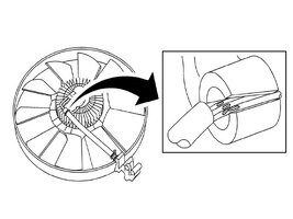
AC-Delco 15-40133 GM Original Equipment Engine Cooling Fan Clutch
Stant 14659 Thermostat And Housing - 190 Degrees Fahrenheit
AC-Delco D1843A GM Original Equipment Engine Oil Pressure Switch
AC-Delco 251-731 GM Original Equipment Water Pump
AC-Delco 251-2029 GM Original Equipment Water Pump Gasket
Cloyes S908 Timing Driven Gear
Engine Block:
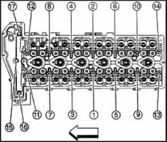
(1) When facing the front of the Engine… the #1 Cylinder is located right in front. You'll have to install the Lower Crankshaft Timing Chain Cog onto the nose of the Crankshaft and then Rotate the Crank CLOCKWISE ONLY until you can see the small circle embossed on the front face of the Cog located in the Lower 4-5 O'clock Position as per the prior posted
Engine Timing Diagram.
(2) You can carefully use either the Old Crank Bolt along with a 1/2" Deep Socket and Ratchet... or use the Flex-Plate to perform this Engine Rotation and observe as the #1 Cylinder comes right up to Top Dead Center. (Piston Top will be almost even with the upper Engine Block Face as you eyeball “The Dot on the Cog” for being in the correct position. At this point… the DOHC (Double Over Head Camshafts) will be in the correct timing position during the pending installation and NOT strike the Pistons from being out of their correct positions once the Engine Head is being installed.
(3) Please note that the Engine Head is NOT yet installed onto the Engine Block during these procedures, so don’t worry if you move things around “past their proper positions”. Just relax and rotate the Crank-Rods-Pistons around again clockwise until you can get things perfectly aligned. Refer to the Timing Chain Diagram I posted previously for this Crank Cog Alignment.
The GM Atlas Vortec 4.2L LL8 Engine Head for DOHC Camshafts Installation:
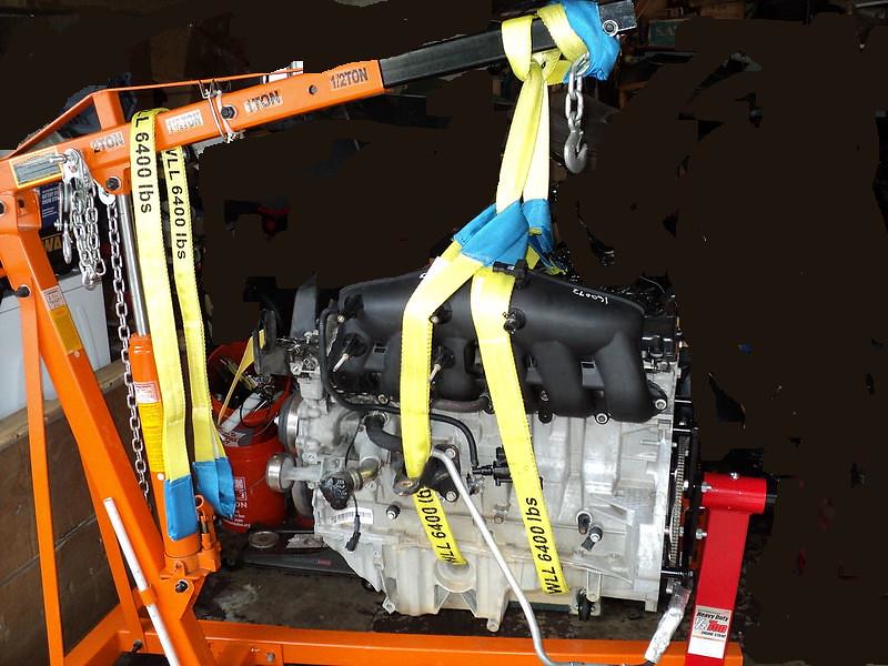
(1) Try to set up a Bench with a working height slightly higher than waist high. Nothing is more fatiguing than having to bend over a long engine head while performing tiresome work that requires concentration and attention to all these details. Be careful not to mar or damage the underside mating surfaces of the Engine Head.
(2) Lay the Engine Head on top of two lengths of 2” X 4” such that the Combustion Chambers and the (4) Valves nested within each of the (6) Six Piston to Head Positions can actuate freely up and down without striking the counter-top surfaces.
(3) Use Spray Cleaning Solvent to clean the upper surface of the Head while paying particular attention to the cleanliness of the Camshaft Journals "Clam Shells". Apply some Engine Assembly Lube (NOT Moly-D Lube) or some Lubri-Plate #105 in the Half Shell locations for each Camshaft Journal and inside of each Cap.
(4) Clean and Lube the small hollow Push Rods and slip them into their proper positions into the engine head along with their Tiny Lubed Roller Rockers such that the rollers will be in direct contact with the Camshaft Lobes and the tops of each Valve Stem once the Camshafts are lowered onto the clam shell spaces for each Journal. THIS Video displays how this should be done:
(5) Thoroughly Clean the Camshafts Lobes and Journal bosses of the Camshafts and ensure that you are installing the Intake Camshaft on the Right side of the Engine Head (when facing the front of the SUV ) and installing the Exhaust Camshaft on the Left Side of the Engine Head.
(6) Thoroughly lube up the Lobes and Journals with the Engine Assembly Lube and carefully lay the Camshaft(s) over their respective Journal Positions. Install the properly numbered Camshaft Caps along the length of the Camshaft… HAND TIGHTENING the two fasteners on each Cap, noting the correct orientation of each Cap. Refer to your original Pre-Disassembly photos if you need to double check their locations and positions.
(7) At this point, the actual rotational alignment of each Camshaft for purposes of Crankshaft to Camshafts Final Timing alignments are unimportant. THAT step will be addressed after both camshafts have been completely installed.
(8) Using an alternating pattern and working your way from the inside Journals outwards… GRADUALLY tighten down the Journal Caps with equal measure for BOTH Fasteners on either side of each Cap in order to avoid bending, binding or damaging the Aluminum Caps or Lobes of the Hollow Camshafts. Work methodically until you are certain that ALL of the Cam Caps are mated onto the Engine Head.
(9) Follow the same pattern of applying the correct
106 INCH POUNDS of Torque and then MARK EACH COMPLETED CAP with a Permanent White Paint Marker after wiping the upper Cap Bolt Heads with a rag soaked in solvent. In this manner you will be certain that each Cap is definitely Installed, Tightened and Correctly Torqued Down.
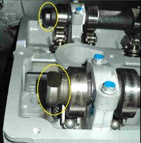
(10) Prior to lifting and placing the Engine Head on the Engine Block, install the Camshaft Holding Tool at the BACK ENDS of the Camshafts after rotating each Camshaft around to position where their Flats on each end are Horizontaland LEVEL. (See Prior Postings for images and instructions).
(11) Install the Exhaust Cam Phaser – Sprocket and Intake Camshaft Steel Sprocket as per @Mooseman’s
Cam Phaser Thread Instructions covered in prior postings in this Thread for using Brand New TTY Bolts on BOTH Cam Sprockets.
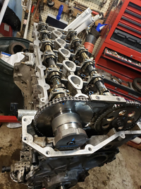
(12) As long as you have installed the New Timing Chain Guides, the New Timing Chain Tensioner and the Timing Chain with one Black Link positioned over the Dot on the Crankshaft Cog and one Black Link over each of the Cam-Phaser Sprocket and Intake Sprocket Vertical markings and confirmed that the word “DELPHI” marked on the front of the Cam Phaser is Level with the Upper, Horizontal face of the Engine Head... then the Engine Timing will be PERFECT.
(12.5) Remember to “Pull the Pin” out of the Timing Chain Tensioner only AFTER all of this work has been completed and recall that you must Rotate the Engine slowly by hand for a total of
(14) Fourteen Complete Clockwise Rotations in order to finally return the #1 Cylinder to Top Dead Center (TDC) and have ALL Three Sprocket Timing Marks shown in that posted Timing Diagram align with their respective Black Link Markings on the Timing Chain.


 It means alot.

