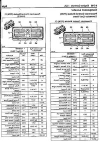
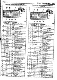
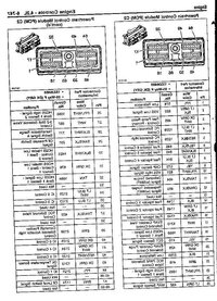
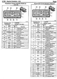
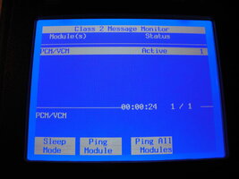
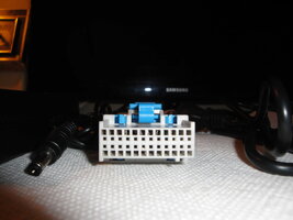
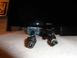
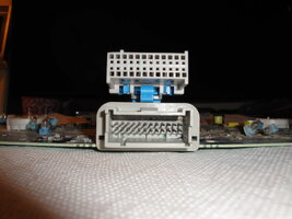
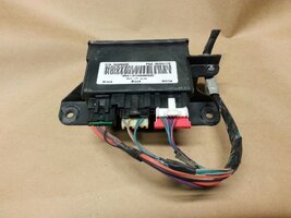
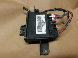
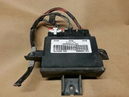
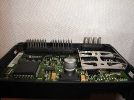
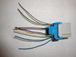
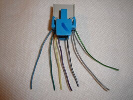
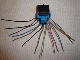
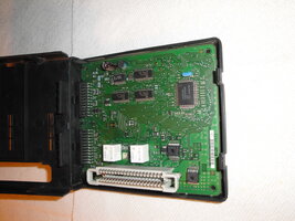
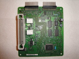
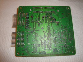
BIGGER EDIT: 04/24/2019
For THE BEST On Topic Solution ...Go Directly to Post # 42...
BIG EDIT:
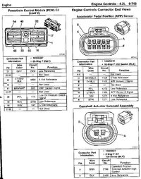
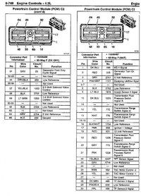
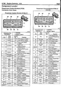
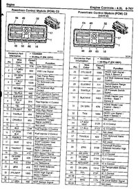
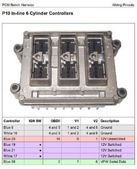
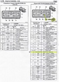
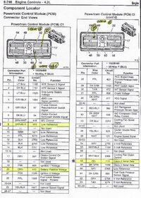
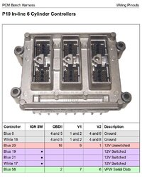
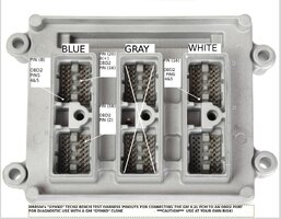
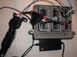
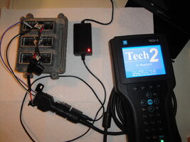
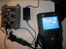
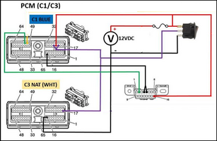
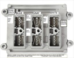
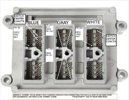
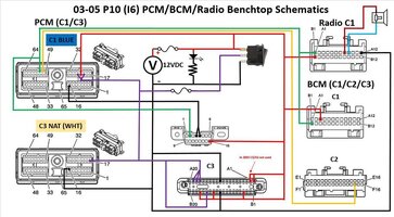
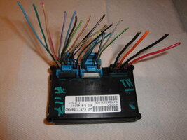
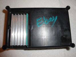
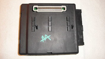
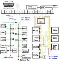
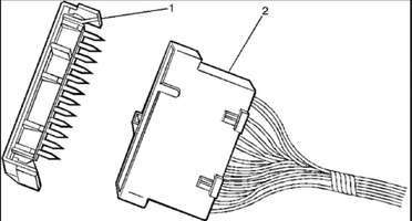
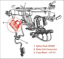
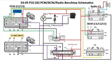
This Thread originally was to cover creating a Test Harness to use exclusively for diagnosing and repairing the GM Trailblazer and Envoy, etc Instrument Panel Cluster and Components... but eventually it achieved a life of its own for Testing and Repairing ANY of the Many GM Modules... as long as they are added properly to the "GYMKO" Bench-Top Harness via the precise mirrored PCM and Harness Pin-Outs. More work needs to be done to take each of these ... The BCM, The TCM, The LGM...etc.... one at a time...and document each and every one of the "Most Likely To Fail" among all of the 'Myriad Modules' residing on the Class 2 Databus.
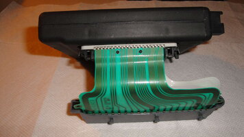
This is an interesting Instrument Panel Cluster Rebuild-Repair Job involving a Professional Re-Fitter of Instrument Clusters receiving essentially a Bag of FUBARed Cluster Components from one of his embarrassed Customers and then essentially performing an UN-FUBAR job and an R&R of misplaced, missing or damaged Stepper Motors. This kind of video is nothing new to those who have had to perform this repair. But what is particularly interesting is the way the E-Tech uses his "GYMKO" Tech2 Scanner to run Bench Top Post Diagnostics to show whether or not his work was successful.
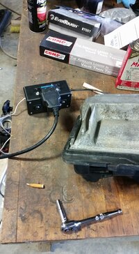
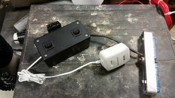
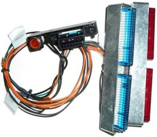
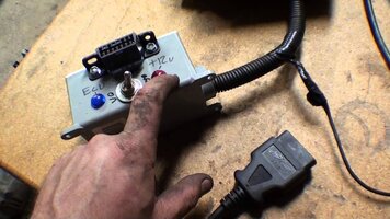
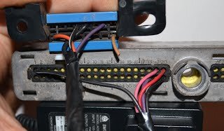
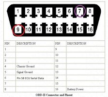
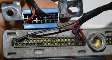
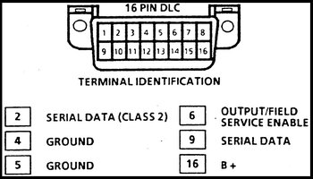
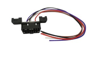
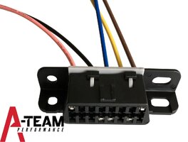
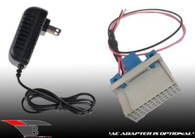
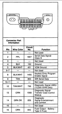
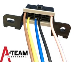
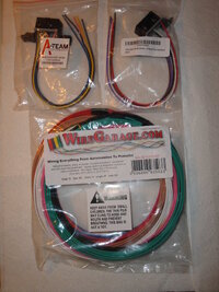
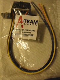
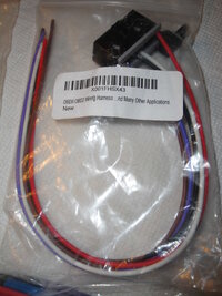
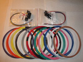
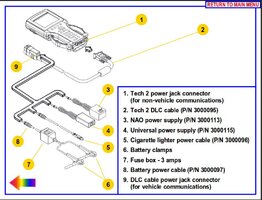
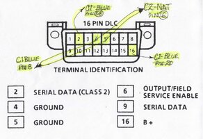
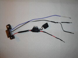
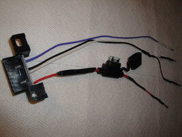
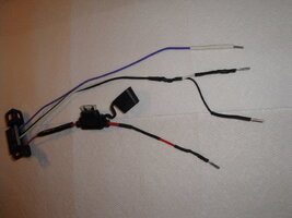
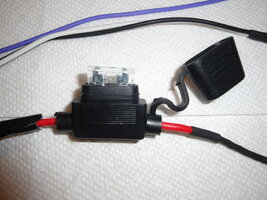
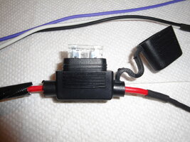
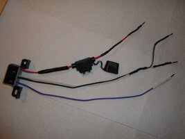
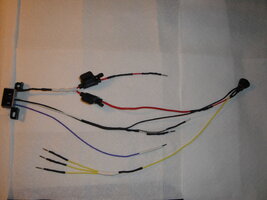
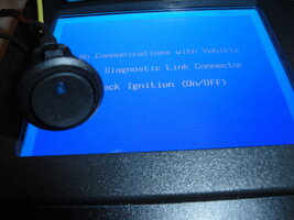
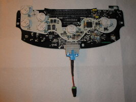
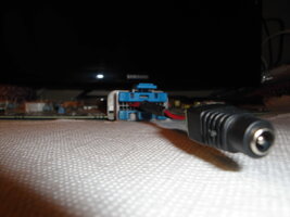
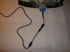
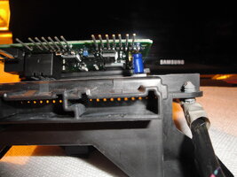
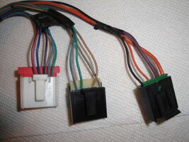
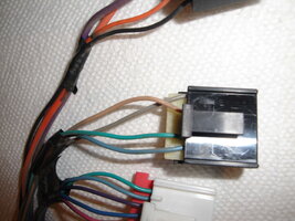
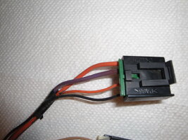
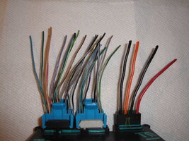
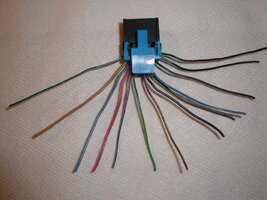
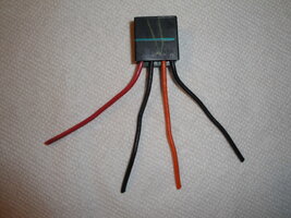
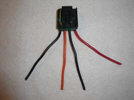
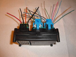
What is Cool also about this video is that this Dude sort of "lifts his skirts" a little to show a separate Homemade Diagnostic Harness that includes the OEM Vehicle Cluster Connector AND a separate OBD2 DLC Connector mated up with some sort of a Half-Assed Wire Breadboard job to allow the use of his "GYMKO" Tech2 to run some neat Bench Tests. I have not looked over any of his other videos to see if he describes how he built this Instrument Cluster-To-Tech2 Powered Test Harness... but it sure would be nice to have one of these for doing these kinds of repairs.
I cannot say that I would blame him for sitting on the secret... as he would be shooting himself in the foot business-wise if the rest of us "GYMKO" Owners knew how he did it. If we have any Members with the 'E-Circuit Savvy' to watch his videos and sort of dope out his Wire Harness connections and choices... perhaps we can reverse engineer it here and then be able to buy the inexpensive OEM IC & OBD2 Connectors and make our own versions of it. Nonetheless... Even if you just did the solder repairs and then plugged it right back into the Truck Harness Cluster Connector... you could power up the Cluster in the Truck B4 completely re-assembling it inside of the Cluster Case... and use Your Own "GYMKO" Scanner to run those very same tests after fixing the Dial Gauges and know for certain...all works well. This would be a very cool thing to be able to do! Many Thanks to the VOP for showing us yet another way to use our "GYMKO" Hand Held Scanner(s). :>)
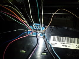
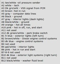
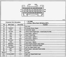
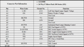
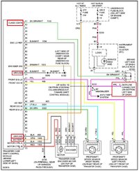
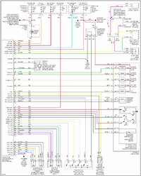
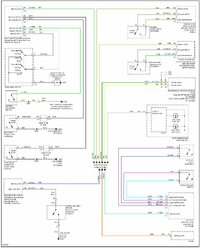
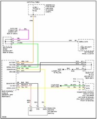
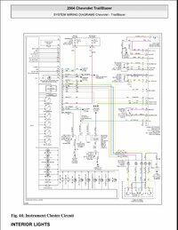
This Attached Image is for the 2004 Instrument Cluster Wiring Schematic for future reference during soldering repairs... (Click on the Image to Enlarge it):

Last edited:

