The $85,000.00 GM 4.2L Engine Repair

mrrsm

Original poster
Lifetime VIP Donor
Supporting Donor
Member
Oct 22, 2015
7,733
Tampa Bay Area
Its another rainy and blustery day here... and thus, the last kind of weather that anyone with any common sense would attempt working on an open topped engine parked out their driveway. Instead... I have used some of the time today to make an order for the requisite Cleaning Supplies needed to do this job right. I like to think about this critical phase of Pre-Assembly using:

"The Three to One Rule" ---- Simply stated, if you intend on using 100% of your Mechanical Skills and Attention to Details during the Disassembly of your Engine... then you must use 300% of that same Skill-Set during the Cleaning and Preparation Phase to ensure the cleanliness of the mating up areas of any and all surfaces that require Gaskets or Seals... and ALL BOLT HOLES CHASED AND SPRAYED OUT CLEAN. They must all be PERFECTLY CLEAN AND DRY before bolting these components onto the Engine Block.

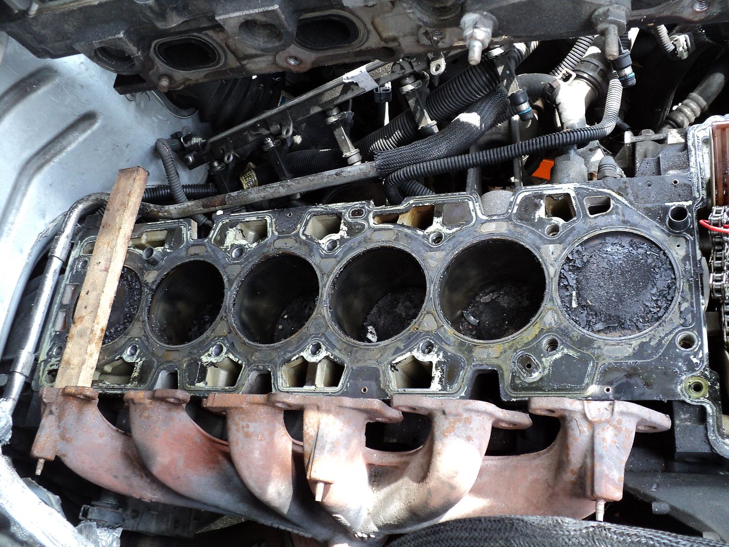
In this case... since I am installing a Brand New Engine Head... my obligation is to clean out the Combustion Chambers and Flat Surfaces of any and all Dirt, Oil, Preservative and Packing Residue with a Lint-Free Cloth...as well as running a Thread Chaser through the Spark Plug Holes. Once cleaned and sprayed down with a Solvent that leaves Absolutely NO RESIDUE... then the Components not being immediately installed should be thoroughly wrapped up in new Saran Wrap to prevent even the slightest contamination before being installed onto the Gasket(s) aligned on the Engine Block and bolted down via the Gospel and Verse of the OEM Torque Pattern and Recommended Torque Settings and finally... finishing off the job with the correct degrees of turn for the TTY settings required for each Fastener.

All of the fasteners that do NOT come with OEM Thread Sealants applied should first be Lightly Wire-Brushed on all the threads and subsequently be washed in Very Hot, Soapy Water and then Immediately Dried with either a Heat Gun... or by spraying down each one with a non-residue forming solvent. Do NOT apply any lubricants without consulting the specifications for fastener installation in the manual FIRST. In some cases... certain fasteners that pass through or dwell within the Water Column or Coolant Passages will require having the proper Water, Oil and Gas Resistant SEALANT applied to the Threads and Shanks to prevent the coolant from leaking out of the block and into places it should not be.

If you have your Fasteners stored inside one location and either the Engine on a Stand or the Engine in the Vehicle is located in another... it will be necessary to "normalize" them by having the Fasteners acclimated to the ambient temperatures where the Engine dwells. You do NOT want a huge temperature variance between them, as you run the risk of Damaging the Engine, Breaking the Fasteners or getting improper Fastener Torque if they are very far apart in how cold or hot these components happen to be when used. Having a temperate work environment when putting Major Engine Components together is conducive to a successful outcome.

Likewise... these fasteners should be placed inside Pre-Marked Plastic Zip-Lock Baggies in their respective sets, depending upon the orders for their installation. In some cases... certain fasteners are to be Oiled on the Threads and Under the Base of the Bolt Head and Hardened Steel Washers to ensure that the Fasteners Do NOT Grab, Stick or Gall under the compressive forces they are designed to ensure an accurate application of High Levels of Torque.

In the case of the GM Atlas 4.2L TTY Head Bolts... I will be defying the Factory OEM convention of installing these Fasteners BONE DRY... by applying an EXTREMELY LIGHT COATING OF 3&1 Oil that will then be very thoroughly wiped clean from the threads and leave only the slightest residue therein. The reason for this contingency is that the GM OEM Reps have made this recommendation due to the extremely high number of these Fasteners Snapping Off during standard installation procedures.

More on Procedures and Cleaning Products in the Next Installment...
 
  • Like
Reactions: Mooseman

mrrsm

Original poster
Lifetime VIP Donor
Supporting Donor
Member
Oct 22, 2015
7,733
Tampa Bay Area
Okay... You might ask... “What in the Name of God's Holy Trousers are you WAITING for, Bobby?... Just drop on The New Gasket...drop on the New Engine Head... Bolt it all down with the TTY Bolts and put on the rest of the necessaries...and Start the Damned Truck Up!”

UmmmHmmmmn... Yeah... Well... I suppose I could do it that way... and perhaps in less than a week... After the Head Gasket begins to Leak...with Compression Loss... and with the wrong fluids getting into everything and making one Helluva mess as well... and of course.. it would mean starting this very Nightmare I am trying to finally Wake Up From... All over again! No. This is the time to re-trench with an improved understanding of what we are dealing with here.

There is a reason why All Aluminum Engines employ devices like TTY Bolts that will stretch and snap back like Rubber-bands for tens of thousands of operational cycles under various climactic scenarios. There is a reason why All Aluminum Engines employ MLS (Multi-Layered Steel) Type Head Gaskets due to the bizarre physics and thermodynamics of expansion and contraction that are constantly at play in a motor that relies upon 1.5 MM Thick Steel Cylinders under very tight tolerances... nested inside and between the components attached to an All Aluminum Engine Block.

At this point...All Hasty Mechanics will be in “Deep Kimshee” if they rush through this part. Here is the very thing that can get us into trouble:

Using Abrasive Scrubbing Pads or Steel Wool... However FINE in Texture it may be...to Clean off Carbon, Rust and Baked on MUNG on anything made of Aluminum... is just asking for trouble!

The GM Atlas 4.2L Lost Foam Molded Aluminum Engine Block and Cast Aluminum Engine Head and Cast Aluminum Pistons all very much frown upon the use of ANYTHING ABRASIVE for the purposes of cleaning their surfaces. Forget about all those intrepid “experts” you've seen on Youtube showing the OPs unnecessarily grinding away at the Carbon and Combustion Deposits using a combination of Abrasive Powders...Steel Wool... Grinding and Polishing Air and Electric Tools.

In this case... The first part of the word “Demonstrations” is .... “DEMON”....

This is because they also demonstrate using an inordinate amount of Demon Elbow Grease to burrow into Heavy Deposits of Combustion Residues that, when using the Right Chemical Stuff... will yield their firm grip on all automotive parts if their field of exposure is well-prepared and narrowly controlled for this intended purpose. There should NEVER be any removal of Aluminum Metal from any parts or surfaces due to “Accidental Contact”. It is completely unnecessary!

For anybody who has ever disassembled a Gasoline Powered Combustion Engine and attempted to remove the Baked on Carbon Deposits on the Piston Heads, their Sidewalls and Ring Grooves knows full well that by simply submerging these components into a container of Berryman's Chem-Dip for a few hours...every last speck of the stuff will come off all of these metal surfaces without the OP having to lift a finger. After being washed in Hot Water and sprayed down with WD-40... Most of these Engine Parts will look Brand New! Nothing Else Will WORK Like THIS! ....NOTHING!


I know... Right now you're thinking, “Okay Bob...We'll give you that... Berryman's Works...Big Deal! But ...How are we supposed to use it...when the Engine is STILL IN THE TRUCK and the Pistons are STILL IN THE ENGINE...and the HEAD SURFACE has all those Oil Holes and Open Coolant Passages that we KNOW should NOT have any Berryman's Chem-Dip coming anywhere near them!”

Well.... “There is Always More than One Way to Skin a Cat”. Engine Block Prep = 1 X 6 Steps to Minimize the problem of scale (Don't Try to Do the ENTIRE Block ALL at Once!) What needs doing here is to Isolate Small Portions of the Engine Block at a time AND COVER UP THE REST OF THE ENGINE! Just work on ONE Cylinder and Piston Area increment at a time...using a combination of Paper Towels to block off holes below the head surface and Blue Painter's Tape to control the laying down of thick beads of Clear Pure Silicone Sealant to create small DAMS around the Coolant and Lubrication Ports and Holes to protect them. This will allow for a shallow amount of Berryman's Chem-Dip access to soak over only the Flat Head Surfaces long enough for the chemicals to dissolve away the Carbon and Combustion Residues.

After a sufficient soak time.... these small “Ponds” of the Chemical Bath can be evacuated with a Turkey Baster...and then wiped clean and water washed with a Damp, Non-Abrasive, Lint Free Cloth. After that, a spray down and wipe with a Non-Residue Creating Solvent will finish the surfaces and they will be clean all the way down to the factory machine marks left in the metal and Ready for the Installation of the Head Gasket and Aluminum Engine Head. The Canned Air can be used all throughout this process to blow away any extra residue of particles or liquids into paper Towels that might get into other wise inaccessible place. Cover up the Engine Block with Saran Wrap during each phase and leave all of the block surfaces covered until the very last minute before the Head Installation occurs.

Cleaning and Safety Materials:

Berryman's Chem-Dip
Clear Silicone Sealant
Blue Painter's Tape
Non-Abrasive, Lint Free Cleaning Rags
Roll of Paper Towels
Curved Turkey Baster
Compressed “Canned Air”
Clear Acrylic Safety Face Shield
Professional Grade Nitrile Gloves (9MIL)
Plastic Bag to Collect All Chemical Soaked Towels/Rags

View attachment 75216 View attachment 75217 View attachment 75218 View attachment 75219 View attachment 75220 View attachment 75221 View attachment 75222
 

Mooseman

Moderator
Dec 4, 2011
25,344
Ottawa, ON
You might have problems getting at the pistons that are low in their stroke since you can turn the engine. I'd just use a plastic scraper and vacuum the remnants. Whatever is left will burn with normal combustion.
 

mrrsm

Original poster
Lifetime VIP Donor
Supporting Donor
Member
Oct 22, 2015
7,733
Tampa Bay Area
That is where a Soft Super-Absorbant White Micro-Fiber Cloths come into play here... Once soaked in Berryman's Chem-Dip and stuffed down inside of the #s 2,3,4, & 5 Cylinders it will help to easily dissolve and clean the Carbon off of the on top of each Piston. Also... In order to ensure that whatever residue of the Chem-Dip manages to slip or seep down between the Cylinder Walls and dissolve the carbon around the Piston Rings... will be vacuumed out and very lightly oiled before the New Engine Head goes on top of the Engine Block.

I will be using an extensive amount of Permatex Super-Slick Engine Assembly Lube applied to the Timing Chain, the Exhaust Cam Actuator Sprocket and the Intake Sprocket as well as a liberal dose over the Cam Lobes and OHC Rocker Assemblies for distribution during the first Manual Interference Test Rotations to ensure proper Timing Alignment and Non-Interference of the Newly Installed TC & Gears and Valve Train to Piston Clearances. Then... after the first 30 Minutes of the First Engine Run-In Time... I will be changing the oil over to Valvoline Racing Oil & K&N Oil Filter along with a quantity of Engine Assembly Break-In Additive for the next 500 Miles of operation to ensure a good distribution of ZDDP in the Valvoline throughout the entire engine and Dual OHC and supporting hardware... even though most people might think that regular Motor Oil will suffice.

Perhaps it would... But I am not taking any chances here by 'going cheap' on any Preliminary or Post-Break-In Lubrication. After reaching the 500 Mile mark... I'll switch back to Mobil1 5W-30 so the O2 Sensors do not get coated with ZDDP and start throwing codes as a result. This is not my first rodeo with engine building... and I am calling back upon many experiences here in order to hedge my bets toward the Best Means of Engine Lubrication on a motor that has been dormant for over two years... I am leaving NOTHING to chance. Before the first firing of the ignition... I'll pull the Fuel Pump Relay and cycle the engine until the Oil Pressure Light on the Dash Panel goes out to ensure that their are no dead spots in the oil distribution throughout the engine.
 
  • Like
Reactions: Mooseman

Mooseman

Moderator
Dec 4, 2011
25,344
Ottawa, ON
After being parked for two years, yeah, it will need the extra lube for sure.
 

mrrsm

Original poster
Lifetime VIP Donor
Supporting Donor
Member
Oct 22, 2015
7,733
Tampa Bay Area
View attachment 75250 “It was the Best of Times... It was the Worst of Times...”
'A Tale of Two Cities' Charles Dickens
Thank you... Mr. Dickens... for reminding me once again by the 'changes in circumstances' that I am indeed a Guinea Pig in my own Mechanical Drama...

Well... Earlier this afternoon... The Famous Aluminum Wedge FELL OUT!... However... just prior to this happening ... I had the perspicacity to have pinioned the Ascending and Descending sides of the Timing Chain so that in the worst of all possible cases... I would not have to follow the below listed instruction should the chain accidentally drop down and fall off of the gear teeth on the TC Crankshaft Sprocket.

I was in there... angling for a better position on the Exhaust Cam side of the chain when the Chain Tension Guide Pressure Shoe suddenly popped upwards and loose from in front of the Timing Chain Tensioner Rubber Pressure Pad. It appears from looking the guide over that the Rubber Pad had long since worn completely through as there was evidence of Metal to Metal Contact wear at the interface between the Guide and the Tensioner... what an enormously stupid piece of engineering the 'Geniuses at GM' managed to cook up for THIS damned thing! Let me see if I have this design figured out...You have ONE Shoe...opposing ANOTHER SHOE... with no means of controlling either one of their positions during the R&R of the Engine Head...which is PRECISELY WHEN YOU NEED THEM TO BE UNDER COMPLETE CONTROL!!!

For The Uninitiated to this Nightmare... In the absence of “A Reasonable Alternative” for sorting things out that are described above...THIS IS THE DOCUMENTED GM OEM FACTORY REPAIR SOLUTION to the problem:

Timing Chain, Sprockets, and/or Tensioner Replacement

Tools Required
•J 36660-A Torque Angle Meter
•J 44221 Camshaft Holding Tool

Removal Procedure

1.Remove the camshaft cover.
2.Remove the engine front cover.
3.Release the tension on the timing chain by moving the tensioner shoe in.
4.Place the tee into the tensioner to hold the shoe in place.
5.Remove the top chain guide bolts.
6.Remove the top chain guide.
7.Remove the exhaust camshaft position actuator bolt.
8.Remove the exhaust camshaft position actuator.
9.Remove the intake camshaft sprocket bolt.
10.Remove the intake camshaft sprocket.
11.Remove the timing chain.
12.Remove the crankshaft sprocket.
13.Remove the cylinder head access hole plugs.
14.Remove the timing chain tensioner shoe bolt.
15.Remove the timing chain tensioner shoe.
16.Remove the timing chain tensioner guide bolts.
17.Remove the timing chain tensioner guide.
18.Remove the timing chain tensioner bolts.
19.Remove the timing chain tensioner.

Installation Procedure

1.Install the timing chain tensioner and secure the tensioner with the bolts. Tighten the timing chain tensioner bolts to 25 Nm (18 ft. lbs.) . Notice: Refer to Fastener Notice in Service Precautions. Important: Every seventh link of the timing chain is darkened to aid in aligning the timing marks.
2.Install the timing chain tensioner guide and secure the guide with the bolts. Tighten the timing chain tensioner guide to 10 Nm (89 inch lbs.) .
3.Install the timing chain tensioner shoe and secure the shoe with the bolt. Tighten the timing chain tensioner shoe bolt to 26 Nm (19 ft. lbs.)
4.Install the cylinder head access hole plugs. Tighten the cylinder head access hole plugs to 5 Nm (44 inch lbs.) .
5.Install the J 44221 with the camshaft flats up and the number 1 piston at top dead center. The crank pin will be at 12 o'clock when the number 1 piston is at top dead center.
6.Install the crankshaft sprocket (1).
7.Install the intake camshaft sprocket into the timing chain.
8.Align the dark link of the timing chain with the timing mark on the intake camshaft sprocket (1).
9.Feed the timing chain down through the opening in the head.
10.Install the timing chain on the crankshaft sprocket. Align the dark link of the timing chain with the timing mark on to the crankshaft sprocket. Important: It may be necessary to remove J 44221 to rotate and hold the camshaft (hex) to align the pin to the camshaft sprocket.
11.Install the intake camshaft sprocket onto the intake camshaft.
12.Install the intake camshaft sprocket washer and bolt.
13.Install the exhaust camshaft actuator into the timing chain.
14.Align the dark link of the timing chain with the timing mark on the exhaust camshaft actuator (1). Important: It may be necessary to remove the J 44221 to rotate and hold the camshaft hex to align the pin to the camshaft sprocket.
15.Install the exhaust camshaft actuator onto the exhaust camshaft.
16.Install the exhaust camshaft actuator bolt.
•Tighten the exhaust camshaft actuator bolt the first pass to 25 Nm (18 ft. lbs.) .
•Use J 36660-A to tighten the exhaust camshaft actuator bolt the final pass an additional 135 degrees .
Important: Rotate the camshaft actuator clockwise relative to the camshaft prior to tightening the bolt.

Notice: The camshaft actuator must be fully advanced during installation. Engine damage may occur if the camshaft actuator is not fully advanced.

17.Install the intake camshaft sprocket bolt.
•Tighten the intake camshaft sprocket bolt the first pass to 20 Nm (15 ft. lbs.) .
•Use J 36660-A to tighten the intake camshaft sprocket bolt the final pass an additional 100 degrees .
18.Remove the tee in the timing chain tensioner to regain tension on the timing chain.
19.Remove the J 44221.
20.The dark lines (1) on the chain should be aligned with the marks on the sprockets as shown.
21.Install the top chain guide.
22.Add Threadlock GM P/N 12345496 on the top chain guide bolt threads.
23.Install the top chain guide bolts. Tighten the top chain guide bolts to 10 Nm (89 inch lbs.) .
24.Install the engine front cover.
25.Install the camshaft cover.

Anyway... No matter what the Moppets at GM say must be done next... I still have all All of My Own Teeth in My Head... Right along with a Few Working Brain Cells and a Few Iideas on what I will do to get out of this jamb. For starters... I have the advantage of the Micro-Cam to get in there and see if there is enough room to work a wrench on the two bolts holding the Timing Chain Tensioner in place. If there is enough room to remove those bolts... I am just going replace the Tensioner with a Brand New.. Pre-Loaded and Locked Tensioner that I can install and yank out the "Golf Tee" holding the spring tension after the Timing chain gets routed around the New Sprocket on the Camshafts.

If not... I KNOW I can get the top bolt out...and then be able to rotate the damned thing 90 Degrees... then release the Ratcheting Lock Lever and push the shoe all the way back inside while looking straight down at it...and slip in some 0.041 Stainless Steel Safety wire into the "Golf Tee" hole to hold the thing in place until the chain is back on the sprockets...and pull out the Lock-Wire to allow the Tensioner to tighten things up after a few hand cranks of the Engine.

These First Four Images Show what the Engine Looks Like WITH THE COVER OFF:
View attachment 75246 View attachment 75248 View attachment 75249 View attachment 75250 View attachment 75228 View attachment 75229 View attachment 75230 View attachment 75231 View attachment 75232 View attachment 75233 View attachment 75234 View attachment 75235 View attachment 75236 View attachment 75237 View attachment 75238 View attachment 75239 View attachment 75242 View attachment 75243
 

Mooseman

Moderator
Dec 4, 2011
25,344
Ottawa, ON
As soon as I read this, I said to myself "Oh no!!!!"

I think you'd be better off to just use a hooked piece of wire to get at the locking lever and pushing the tensioner piston back in using the wedge tool. I'd recommend getting the wire in place before putting the head on, then install the the head and shoes, pull the wire and push the adjuster in with the wedge tool tight. You can really jam it in there since the adjuster will be at its most compressed position and can't be damaged really.

If all else fails, I don't think your plan of replacing the tensioner with the cover in place will work. Not enough room. The golf tee is not that easy to pull. Trust me. You'll have to be able to pull it straight out. You'll have to get that cover off. Oh, and since you have the first version of the harmonic balancer with that plate in front of it, you'll need the special tool because a three arm gear puller won't work.

The wear on your shoes looks normal to me. I don't see where the chain wore through the plastic inserts. The shiny worn part on the back side is the tensioner rubbing on it.
 

mrrsm

Original poster
Lifetime VIP Donor
Supporting Donor
Member
Oct 22, 2015
7,733
Tampa Bay Area
Yeah... I've looked everything over quite a few times since my last post and after checking the instructions and reading about the "18 Ft Lbs" required to torque the two tensioner bolts... I realized, without even getting to see any free or loose fasteners... that the Steel Bolt Length required to handle that amount of "squeeze" into the front of the Aluminum Engine Block would have to be fairly long... So long enough in fact, that upon attempting the removal of the Bolts, they would impact against the inside of the Timing Cover "long" before they would be out far enough out to clear the block...so yes.... I had been thinking along those similar lines too. You know how my mind works, @Mooseman ... with "idea streams" that always have to be whittled down before acting upon them...and never before I "put it all down on paper"... I get "A Thousand Bad Ideas"... before I can ever come up with... "One Good One".

Even though I will avoid having to EVER pull the Harmonic Balancer... A few years ago... I bought the Factory 4 Piece Special Harmonic Balancer Puller Tool Combo Kit, just to have it on hand against the advent and outcome of a "Worst Case Scenario".


s-l1600.jpg


Where I have been focusing my attention since this latest problem reared its Ugly Head has been on understanding the design and actuation of the Tensioner itself... as you can see from the photos... it looks pretty straightforward as far as the lever with the 0.060 Hole in the Tension Hold Lever. When the new one arrives... I will reverse-engineer it with my 'Jedi Mind Tricks' to figure out how to defeat its powers.......^........^ (Two Light Saber Swings *Voohm, Voohm*)

9-5512__ra_p.jpg


The only mystery left for me to figure out is which direction it "unlocks" and disengages that little "rack & pinion" ramp along its bottom side and then using my "Mad Inventor" Skills... use a long, slender piece of one of the Stainless Steel supports you find inside of Windshield Wiper Blades...and figure out how long and how thin it needs to be to shape it into an "L" bend and make it a useful "Houdini Tool" for "Jail-Breaking" the locking mechanism and then hold the Tensioner back long enough for this repair to be finished. What t I am after is to be able to not only disengage the lock inside....but re-set the lock into a "Tension Holding" position that I can invoke after the chain, Exhaust VVT and Intake Sprockets are properly "Black Link" oriented before releasing the tension arm against the back side "foot' of the Chain Guide.
View attachment 75256

I find it interesting in the below listed image of the back side of this item ...that it has what looks like an oil lubrication hole along with a lubrication channel as well. I suspect that the durability of this thing would be greatly enhanced if it were being "pressure" washed with oil from the inside, although it does not look like they considered allowing the oil to go straight through a hole in the VVT side Chain Guide and actually spray fresh oil onto the chain as it rolls by the device... THAT would have made WAY TOO MUCH SENSE! I am wondering if there is a way to remove the old, worn out Light Green Plastic Tensioner "footy" cover as shown below and swap in a new one instead!

View attachment 75255


I have also discovered one other interesting thing about the Tensioner Guides... is that their durable (but now worn down ) plastic inserts are quite easily removed and re-installed!. This reveals another way that the "Stealerships" can effectively "re-new" both of the Chain Guide Ramps and still charge for the time in labor it would normally require to completely replace them! I suspect this is part of what they do when using the Aluminum Wedge Tool when performing an R&R of the Engine Head or when doing the Camshaft VVT Actuator Sprocket Repair. I have ordered a kit this morning that includes the Two Chain Guides, The Overheard (TOP) Chain Guide, The Chain itself, and a New Tensioner as well. I will scavenge and rebuild what I need in the way of "renewal" parts that I can install without the necessity of pulling the Front Timing Chain Cover and the Oil Pan. One last observation here is that all of this adjustment re-setting would have ultimately been necessary anyway because even though the Chain is NOT being replaced... The lack of wear and tear on the Two NEW Sprockets in the loop would probably have needed the tensioner to be re-set... just to be able to re-insert both sprockets back on the ends of the two camshafts! Are we having FUN yet?
 

Mooseman

Moderator
Dec 4, 2011
25,344
Ottawa, ON
The tensioner is actually oil pressure fed and that is what adjusts the tensioner. As the chain, gears and shoes wear, the oil pressure pushes the tensioner to the next click. That ratchet mechanism is what holds it at idle. That's what the problem with mine was. The ratchet wouldn't hold at idle and made the chain rattle at idle but was perfectly fine above idle.

But you're right, you would have had to retract the tensioner with the new parts. I still think your best option is to use a piece of bent welding rod of the proper size to pull the arm and use the wedge tool to push it in. Don't worry about the tension after everything is installed and you pull the wedge tool. You could just turn the crank back and forth to get the spring in the tensioner to take up most of the slack, if any. Once it's running, it will adjust itself with the oil pressure. Remember that mine was loose at idle and never jumped a tooth.
 
  • Like
Reactions: mrrsm

mrrsm

Original poster
Lifetime VIP Donor
Supporting Donor
Member
Oct 22, 2015
7,733
Tampa Bay Area
@Mooseman ... My present contemplations remain upon sorting this problem out... in line with your suggestions... and perhaps with another novel, mechanical assist in the approach to the area and access to the components. I'll know better when the Parts and Pieces arrive and I can get a better look at "The Enemy" by trying out my ideas "On the Bench" first... to see if they merit the effort. Here are some enhanced views of "The Battlefield" for those of us interested in observing what is about to happen:

View attachment 75265 View attachment 75266 View attachment 75267 View attachment 75268
 

mrrsm

Original poster
Lifetime VIP Donor
Supporting Donor
Member
Oct 22, 2015
7,733
Tampa Bay Area
Although this Video OP is narrating in Spanish and I am only able to understand portions of his description of the problems this engine encountered... its rare visual value for our purposes of understanding things is unmistakable. In addition, it is impossible not to feel genuinely sad for the OP, his Mechanic and their circumstances, so obvious in how drastic this Engine Failure really was. Nonetheless, I can make some observations of these events that bear mentioning in the context of our present pains and efforts to continue with our own repairs... WITHOUT HAVING TO GO TO THIS EXTENT TO GET THE REPAIRS DONE!

We have been frequently advised by @Mooseman that trying to avoid the need to expand the repairs to this level is IMPERATIVE ... because it involves an enormous addition of time, effort, money, discomfort, delay and the exponential increase in the number of things that can GO WRONG... even with the Slightest Mistake in the Mechanic's performance!

I am also recommending this video for Download and Freeze-Frame Screen Captures for the following reasons:

(1) Judging from the "Over-Cooked" Black and Gooey conditions of the Baked Motor Oil coatings and the enormously sticky looking residue throughout the entire engine... I am suspecting a combination of the use of Low Grade Organic Motor Oil with a High Sulfur and Phosphate content. Likewise... either the use of Poor Quality Oil Filters or the lack of the frequency in making Regular Oil Changes have all conspired to make this motor look so dreadful inside. I realize that there is sad economic reality that many people simply cannot afford the Very High Prices for Pure Synthetic Motor Oil (Mobil1 & Amsoil, Royal Purple, Castrol Syntec, etc.) and Very High Quality Oil Filters (K&N, Amsoil and Mobil1)... But if an Owner CAN afford these necessary Support Lubrication Items... They would be crazy to do otherwise and use anything else! THIS is what happens to Organic Motor Oil in these unfortunate conditions.

(2) It appears that the Oil Pick and contact locations adjacent the Front Cover Gerotor Oil Pump area might have been compromised; either by Failing Oil Pressure or a Total Stoppage inside the Oil Pick-Up Tube due to a Completely Clogged Pick-Up Screen; all in contribution to the collapse of the lubrication system's ability to function. The Thickened, Residual Oil in that Oil Pan is as murky as the La Brea Tar Pits!

(3) The presence of Iron Oxides and a heavy build up of Mineral Scale leeching out indicates a lack of using anything other than Plain Water for the Engine Coolant. Unfortunately, the Lost Foam Aluminum Engine Block will break down internally very rapidly without having the appropriate 50/50 Mix of Coolant to Distilled Water to prevent it from being chemically attacked with added deposits internally in this manner.

(4) The Views the OP provided from underneath the vehicle demonstrates the extreme difficulties to be encountered when having to partially tear down the suspension to access and take the GM 4.2L Engine Oil Pan off while it is still inside the vehicle and under less than pristine working conditions of doing so on the bare ground. This job would still be extremely difficult to do... even inside a covered garage with concrete floors...let alone outside.

(5) Imagine the difficulty of trying to lay proper beads of the right GM RTV Sealant along the edges of all the Flanges on the Front Cover and the Oil Pan and then install the Oil Pan and Front Cover from the front and from under the vehicle within the correct curing time for this "Gasket-Less Nightmare!" What an INCREDIBLE HASSLE!

(6) The Video shows that the Mechanic did NOT have the engine rotated into the correct position of having the #1 Cylinder in the TDC Top Dead Center Position before removing the Engine Head. This means that it will be very unlikely that he'll be able to re-install the Timing Chain Set in the proper Timing Position to install the Engine Head without having many of the Valves striking the Tops of the Pistons. In short... this repair is headed for an absolute DISASTER!


mrrsm

Original poster
Lifetime VIP Donor
Supporting Donor
Member
Oct 22, 2015
7,733
Tampa Bay Area
The Gulf Storm moving in from the west has Shot the Hell out of the day as far as continuing to work on the Engine Head Clean-Up and Preparation. After going over the Removed Engine Head and reviewing the Top Down views of the Engine Block Cylinders... I have had an unusual idea about how to remove the ridiculous collection of Carbon and Post-Incomplete Combustion Residues that accumulated after 240,000 Miles of operation. This notion that keeps percolating in my "coconut" might seem outrageous...but my reasons for thinking that it might work are as follows:

Although not as radical as the later Chrysler "426 CID Hemi" Engine ...the Precursor Motor... The Chrysler 392 CID "Hemi" had, along with it's very large cubic inch displacement...a Two Valved, Deep-Domed, Hemispherical Shaped Combustion Chamber Design that used a centrally located Spark Plug to ignite the Fuel and Air it inhaled, compressed and burned while providing a powerful combustion pressure wave inside that directed its force downwards from every single point inside the hemisphere in the upper chamber towards the very Dead Center of the Piston Head.

There has never been an engine with this combustion chamber design that was not capable of producing incredible amounts of horsepower... just look at the Mopar "Slant Six"...which essentially was... a 426 Hemi... Cut in Half... with two matching cylinders added. That little engine would burn off the tires of the average panel truck using it... like Butter... and do so while sporting only a Two Barrel Carburettor!


It follows that in some ways... GM Atlas 4.2L Engine Head...with its 24 Valve and a "Slightly Hemi" Combustion Chamber Design is key to its ability to create horsepower in the range of 270-300 RWHP with an inordinately large cylinder displacement as well. I won't belabor everything else we already know about this remarkable power-plant... other than to mention here that we may be able to take great advantage of these similarities with the Chrysler Engine to solve the problem of the awful build-up of Carbon Deposits.

Over time, these combustion remnants collect like an inverted condition of having "Ashes in a Fire-Place" and destroy its efficiency, ruin the correct "quench" area for stoichiometric perfection and labor the ability of the Four Valves Per Cylinder to "Cast off the Yoke of Carbon" that obviously chokes the life and power out of the engine. If you were to take the measurement of the circumference of each Valve and add to that the length of the Circumference of all the intake and exhaust ports they seat upon... then you would have one single, long edge that winds up being the very place where the waste products of incomplete combustion happen to collect. With the eventual accumulation of all this crap... the valves soon find themselves being crowded off of their seats..with an insufficient amount of Valve Spring Pressure to completely close these obstructed Valves... compression loss is inevitable due to the poor sealing that comes with the problem.

But here is where the solution to the problem becomes possible. Since the Atlas engine sits perfectly flat on level ground and since the highest point in the interior of the combustion chamber is coincidentally at the spark plug hole... I am proposing that it would be possible to remove all of the engine plugs...and one cylinder at a time (two actually... #1 & #6...if you have the #1 Cylinder at TDC)... you could Tube Fill the Combustion Chambers through each Spark Plug Hole to the very BRIM with a Carbon Dissolving Chemical for a sufficient length of time to Dissolve ALL of the Carbon Detritus. Trust me here... EVERYTHING IN THE UPPER COMPRESSION ZONE OF THE CYLINDER ALONG WITH ALL FOUR VALVES WILL BE COMPLETELY EXPOSED AND SUBMERGED IN THE "CARBON-BUSTING" CHEMICAL... RIGHT UP TO THE VERY TOP OF THE SPARK PLUG THREADS!

Then it would be a simple matter to Vacuum Out the Black Liquefied Carbon Residue out of each Cylinder. After two or three treatments like this with say... Pure Liquid Sea-Foam or with using the GM Top-End Carbon Cleaning Kit... virtually ALL of the Carbon Build-Up could be eliminated... without the usual results that come from getting small puffs of these chemicals at a time to work while the Engine is actually running. THIS IS THE EASIEST TO USE DEVICE AND THE MOST ACCURATE TOOL DESIGNED FOR THIS SPECIFIC PURPOSE!

View attachment 75293

Now obviously... you would have to choose wisely from the available Chemical Liquids with a reputation for being "Carbon-Busters'...keeping in mind that if the stuff is TOO strong... it might soak deep enough into the Rubber or Viton Valve Guide Seals and cause them severe damage... so choosing wisely here it the key. I am really not too concerned about this happening though... because only the Cylinders positioned at TDC with ALL FOUR VALVES CLOSED... should receive this "dunking" of the concentrated "Carbon-Buster" Liquid and the Valve Stems are NOT exposed to the chemical(s) under this condition. Naturally... this might take too much time to do on ALL Six Cylinders... but doing one one per week for six weeks when the Engine hits the 100,000 Mile Mark ...along with a follow up Oil and Filter Change...would be the correct thing to add when doing this "Carbon Busting" Procedure.

I have an uncommon advantage that will allow me to test this theory by inverting the Old Atlas head with its 240,000 Mile Carbon Build-Up and have easy access to all cylinder hemispheres with closed valves once the Engine Head "Turtles" on my work bench. I can pour in different cleaners in each one and observe whether or not the carbon dissolves in each one within a reasonable amount of time. What I need now are some recommendations from our members who use these products as to which chemicals or products should be tested and then...set up the experiment accordingly.
 

Mooseman

Moderator
Dec 4, 2011
25,344
Ottawa, ON
A buddy at work who used to be a mechanic at a GM Dealer told me about ACDelco Cleens Combustion Chamber Cleaner. I asked him about something to help my son's Prelude that was burning oil and he recommended this stuff to unstick piston rings. I also used this to clean the EGR passages on the same engine and the carbon would just melt out. It didn't help with the oil burning though.

You do realize that you won't be able to fill the cylinder and the liquid will remain there. It will seep out though the rings. I'd just spray Cleens with the head off, wipe it with a rag and call it a day. Don't overthink the simple stuff.
 
  • Like
Reactions: mrrsm

mrrsm

Original poster
Lifetime VIP Donor
Supporting Donor
Member
Oct 22, 2015
7,733
Tampa Bay Area
I wasn't thinking of employing this technique under the present conditions... I was simply "Brainstorming on a Rainy Day" for the possibility of doing this on a fully assembled motor in need of a REALLY complete De-Carbonizing. The description I advised on about using my own Carboned Up Head was that it was just too good of an opportunity to miss as a Test Bed for trying to figure out what chemicals would work in the least amount of time (well before completely seeping past the rings...but still not running out of fluid because of a tube filled up with the cleaning fluid and with a liquid proof seal around a compression test fitting...screwed into the Spark Plug Hole) using suggestions... just as you just made for the GM "CLEENS"... for chemicals that will work towards the most efficacious outcome. I have already described how I intend to Prep the New Engine Head in two prior posts... so no... I won't need to try out this particular idea on the present repair job.

EDIT:

Down south from the GWN... They sell the same CLEENS product and call it GM TOP ENGINE CLEANER. I am ordering 4 Cans of the stuff and will try it first....and if it does not take off absolutely everything from the Engine Block... I'll continue on with my original plan to use the Berryman's Chem-Dip stuff
:
71B838%2B1coL._SL1500_.jpg


I'm in this situation up to my eye-brows right now... so for all intents and purposes... I want to ask ...and hopefully, answer as many questions as I possible can, since I doubt that in my lifetime... any living human soul will ever delve into this process as deeply as we are covering things here. And... since the Mailman just delivered the latest "Experimental Equipment"... it follows as a good segue that I am using the very same investigative technique in the instance of the problem with the Tensioner... because well before I reach down inside the front of my engine to attempt working on that Tensioner... I just want to know exactly how these things really work. Now that I have had the thing in my hands to examine more closely... This is what it looks like and the images better inform me ( and for our other members, too) as to how it functions and can be controlled the next time I get after it. I have an idea in mind to try something new to deal with the problem of it springing open after being compressed... One final thing worth mentioning here is that this set of images should reinforce why using only OEM Factory parts for repairs like this will do.... These roughly machined parts will never go inside the the Atlas Engine:

View attachment 75297 View attachment 75298 View attachment 75299 View attachment 75300 View attachment 75301 View attachment 75302 View attachment 75303 View attachment 75304 View attachment 75305 View attachment 75306 View attachment 75307 View attachment 75308 View attachment 75309 View attachment 75310 View attachment 75311 View attachment 75312 View attachment 75313 View attachment 75314 View attachment 75315 View attachment 75316 View attachment 75317
 

mrrsm

Original poster
Lifetime VIP Donor
Supporting Donor
Member
Oct 22, 2015
7,733
Tampa Bay Area
Okay… I know that this looks like I'm about to Ride Right off The Mental Reservation here… But I cannot shake this idea out of my Coconut and if I don't at least throw it all down on paper and discuss this possibility… then I'll never know if it is worth pursuing. This concerns the following Crazy Notion:

I think it might be possible to replace the timing chain on the GM Atlas LL8 4.2L Engine WITHOUT HAVING TO REMOVE THE FRONT TIMING CHAIN COVER AND WITHOUT RISKING THE CHAIN JUMPING TIMING OR SLIPPING OFF OF THE CRANKSHAFT COG…

The Regular Tools Required:

(1) Proper set of OHV Camshaft “Chain Breaker and Riveter” Tools
(2) 8mm Pitch Temporary “Master Link” Three Component Set (Mercedes Benz makes one)
(3) Brand New OHV Camshaft 8mm Pitch Replacement Male Link for Final OEM Quality Riveting
(4) Oxyacetylene Rig and Brass Brazing Rods & Flux to Braze the Steel Superstructure together
(5) Lock Wire (Safety Wire)
(6) Large Zip Ties
(7) [4] High Grade 10mm Nuts, [2] High Grade 10mm Short Bolts

An Irregular OHV Timing Chain “Swap Tool” of my Own Design:

(1) A Section of 1” Square Stock Hollow Steel Tubing of sufficient length to contain the Timing Chain.
(2) A Section of 1 1/4” Sq. Stock Hollow Steel Tubing Brazed to the Base (Telescopes the 1” Tubing)
(3) 4” X 6” Section of 1/4” Plate Steel with a 1 1/4” Hole Center Cut in the plate to act as a Conduit.
(4) Two Pieces of 3/16” X 1” Flat Stock Mild Steel of sufficient length to support the Intake Sprocket.
(5) A VARIABLE # of Fasteners: Bolt & Locking Nut Combos Through-Bolt for the Intake Sprocket.
(6) GM 4.2L Intake Camshaft Sprocket.

How it all Fits Together:

The 4” X 6” X 1/4” Plate Steel has a 1 1/4” Square Hole Center-Cut inside. The 1 1/4” Square Tubing Brazed to the Base allows the 1” longer Square Steel Tube to telescope up and down inside and guides the Old Timing Chain as it passes up through the tubing to completely encircle the Intake Sprocket, mounted like a “Ferris Wheel” between the Two Flat Mild Stock Steel pieces. Those two items are drilled on one end to accommodate the Sprocket Bolt and supporting it like a “Ferris Wheel” on inverted Bicycle Forks,

The Two Flat Mild Steel Pieces are cut to a length and after being drilled out at their tops for the bolt acting as the axle holding the Intake Sprocket… they are Brazed to the opposite sides of each other on the 1” Square Steel Tubing. The Old Timing Chain is fed vertically through the middle of the 1” Square Steel Tube that is telescoped inside of the 1 1/4” Tubing Base. The Old Timing Chain then goes around the teeth of the unmounted Intake Sprocket which is then slid up from beneath the Timing Chain to a height that snugly engages all of its available teeth. The Intake Sprocket is then bolted between the Two Flat Mild Steel Pieces... with two sets of Oversized Plastic and Steel Washers to provide some restrictive friction from free rotation when The Device is in use.

The Overall length of the 1” Square Steel Tube should be long enough to take up ALL of the slack in the Old Timing Chain and still reach all the way down inside the Engine Block, if there is enough clearance, almost to the top of the Timing Cover Bolt to ensure that the two sides of the Timing Chain are always in very close proximity to each other and cannot slip off of the Crankshaft Sprocket just below. Drill out 2-11mm holes about 2” above the base of the 1 1/4” Square Tube and then Braze or MIG Weld one 10mm Nut over each hole. Then spin the other 2 Nuts on the Short Bolts and loosely screw the Bolt/Nut Combos into the Brazed on 10mm Nuts. When the inner 1” Square Tube with all of the elevated apparatus described above has been correctly installed and lifted to take the slack out of the Timing Chain ...then use a 10mm Box End Wrench to tighten down each Bolt on both sides and finish with tightening down the 10mm Lock-Nuts as well for Good Measure.

More to Follow...


View attachment 75376 View attachment 75377 View attachment 75378 View attachment 75379 View attachment 75380 View attachment 75381
 

Mooseman

Moderator
Dec 4, 2011
25,344
Ottawa, ON
Okay… I know that this looks like I'm about to Ride Right off The Mental Reservation here…

Yes.

The question is why bother with the chain? It's probably the least likely to break apart from the gears themselves. And you still have to retract the tensioner.
 

mrrsm

Original poster
Lifetime VIP Donor
Supporting Donor
Member
Oct 22, 2015
7,733
Tampa Bay Area
How would this Proposed Device Work?

First and foremost…. The Engine MUST be rotated to place the #1 Piston at TDC...with the Engine Head Removed after painting proper White Permanent Paint Markings with Crankshaft Position designated at TDC. Finding this position with repeatability is critical and without said marks… Impossible. The Engine will eventually be rotated through many, full 360 Degree Cycles AFTER the Initial Thread-On of the Brand New Timing Chain has been completed. Once that is achieved...the aforesaid device is re-checked for chain tightening and secure lock-down of this tool before cycling the rotating assemble enough times to arrive back at the original #1 Cylinder positioned at TDC. After securing the New Timing Chain with the K&M Adjustable Timing Chain Holding Hooks… all the newly designed and fabricated “Timing Chain Swap Tool” equipment will be carefully removed. After that the Timing Chain Tensioner will be have to be re-compressed and the Aluminum Wedge re-inserted to hold the Tensioner in place long enough to relax the hold on the New Timing Chain and allow for the Engine Head Gasket and Head Installation to proceed.

The Step By Step Set-Up Procedures:

The “Timing Chain Swap Tool” is first set flat and square on its 4" X 6" Base on the front section of the Engine Block over the access area that the Timing Chain passes through...(WITH THE ENGINE HEAD REMOVED) and then the “Red Guide Wire” attached to the Timing Chain is fed first through the Base 1 1/4” Vertical Square Tube and then into the inner telescoped 1” Square Tubing until it exits out the top of the smaller tube. The rest of the Chain is pulled through as far as it will move and then spread open enough to accommodate the insertion of the loose Intake Sprocket. The Sprocket is then moved upwards in between the two Mild Steel Flats and is pinned in place just like a “Ferris Wheel”. Then when the Through-Bolt with oversized Plastic and Steel Washers...passes through one side support plate...then through the hole in the axis of the Intake Sprocket and finally out the other side. The second set of oversized washers is applied and the Bolt is secured snugly...with a sufficient number of these washers and a Locking Nut to prevent any wobble as the Sprocket rotates… but loose enough for it NOT to rotate freely.

After this… the opposite end of the 1” tubing is gradually lifted until all of the play or slack is taken out of the Timing Chain and then the two 10mm Locking Bolts are tightened down securing the two Square Tubes together… with the Lock-Nuts also tightened down for added protection from slippage. In this configuration… the Timing Chain will rotate easily around the Crankshaft Cog and remain as consistent as it would if the Engine Head and the Intake and Exhaust gears were still in place... with the normal routing of the Timing Chain. The narrowing dimension of the inner 1” Square Tube guarantees that the two sides of the chain will remain “Pinched” together… roughly in the center area of the Engine block and not slip or “drop a tooth” when the rotation of the Crankshaft occurs.

How is the New Chain “Swapped In”…? (This will READ more Complicated than it is...)

This is where the Tool Design becomes very helpful. First… The area to be separated that will be consistent with the Black Links moving around in an identical length of separation is identified and marked on the New Timing Chain. Next, both sides of the Old Timing Chain are temporarily secured at the point where the the two sides exit the very top of the 1” Square Tube using a length of 0.041” Safety Wire. This action will ensure that the Old Timing Chain does not slip off of the Intake Sprocket and simply fall down the inside the Tool to the bottom of the engine during the setting up and positioning of all this hardware and defeat this entire effort.

Next, the “Chain Breaker Tool” is employed to separate the Chain at a single, common, matching link point between the Old Timing Chain and the New Timing Chain. Once orientation takes place… that entire link is removed and in its place… The Master Link will be inserted with the Old Timing Chain positioned to descend down into the Engine Block … and with the Master Link securely connected up to the New Timing Chain, it can be fed Over the Top of the Intake Sprocket.

The ascending side of the returning Old Timing Chain is allowed to drape over the left upper side of the 1” Square Tube and has a small weight attached to its end with a short length of 0.041” Safety Wire to keep the chain from falling back down inside the tube and provide the positive means to Gravity Pull on the Return Chain until the Master Link makes the full rotational circuit and emerges out of the ascending side of the 1” Square Tube.

Next… with the setting up of this transfer complete… the Security Safety Wire previously applied at the top neck of the 1” Square Tube is cut and removed and the Crankshaft is then VERY slowly rotated Clockwise… The New Chain is very carefully guided/fed onto the upper sprocket ...as the ascending, Returning Old Timing Chain is allowed to come up and out and drape over the left side of the tube. Careful attention to their separate and distinct alignments must be attended to at all times. Having a second person to assist will make things much easier...with one person taking up the slack of the return chain...while the person actually slowly turning the Crankshaft is feeding the New Timing Chain onto the Intake Sprocket and stops when the Master Link comes into view on the ascending Top Side of the 1" Square Tube.

It has occurred to me that if the Intake Camshaft Sprocket is allowed the ability to "freewheel" too easily...then the New Timing Chain might get away from being under compete manual Control and very easily roll off the Sprocket towards the descending side of the tool. I think this can be prevented by using some Large Plastic Washers and Large Metal Washers to sandwich the Intake Sprocket with enough just enough tension on the Through Bolt and Lock-Nut to squeeze the Sprocket Just Tight Enough... that when releasing hold of the New Timing Chain and Intake Sprocket during the Threading On process... the Intake Sprocket won't simply "Free-Rotate" from the weight of the Descending New Timing Chain and completely roll off of the Intake Sprocket Gear Teeth...but rather stay right in place unless being rotated by the force of the Manually Advancing Crankshaft. I will test the pre-assembled Tool in a Vise first using a Spare New Timing Chain and see what if any adjustments need to be made before using the device on the Engine.

The entire area around where the following work must take place MUST be covered and protected from having any of the parts or pieces of either the New Timing Chain, The Master Link Kit, The OEM Permanent Link Kit or any of the Tools in use... from Dropping or Falling Accidentally Down Inside the Engine!

The Last Critical Steps are to Secure Both Sides of the New Timing Chain at the top end of the 1” Square Tube with 0.041” with Security Safety Wire at the upper neck. Then to remove the Temporary Master Link and substitute it for The Permanent OEM 8mm Pitch Chain Link. After the OEM Chain Link Side Plate is properly positioned… the “Riveter” portion of this Tool Kit must be used to “Compression Peen” over the two pins and complete the construction of the Brand New Chain. Care must be taken during the removal of the Tool paraphernalia and ensure to maintain tension on BOTH sides of the Timing Chain using the K&M Timing Chain Retention Hooks prior to cutting the 0.041” Safety Wire to prevent the New Timing Chain from dropping off of the Crankshaft Cog.

And so.. as the Intake Sprocket is unbolted from the tool, the Loose Chain is held tightly upwards while the Square Base and the Inner 1” Tubes are loosened and lifted up off of the Engine Block. Right then... the New Timing Chain likewise MUST be Lifted UP tightly on Both sides and secured with either taught Safety Wire or with the OEM K&M Chain Retention Hooks long enough to allow for the Timing Chain Tensioner to be compressed and re-set and the Re-Installation of the Aluminum Wedge between the Inner Timing Chain and the Timing Cover Bolt. Following all of these proper procedures and taking all precautions will allow this job to go smoothly.

As always... whenever I'm working through ideas for building and using something like this “Franken-Chainer” … Any and All Suggestions, Criticisms and Alternative Ideas are requested and Welcome… from our GMT Nation Members
 

mrrsm

Original poster
Lifetime VIP Donor
Supporting Donor
Member
Oct 22, 2015
7,733
Tampa Bay Area
Yes.

The question is why bother with the chain? It's probably the least likely to break apart from the gears themselves. And you still have to retract the tensioner.

Question: The question is why bother with the chain?

Answer: I agree that this is very risky...but until somebody tells me definitively that it cannot be done... I will probably proceed....and the reason is the Extreme High Mileage of 240,000 Miles this engine has endured and I just have the weirdest feeling that if I don't do this... it will be the next thing to fail...and of course... if that happens...Bye Bye Motor. The reason has to do with the almost complete expansion of the Chain Tensioner that would only allow the Aluminum wedge a very small entry-way down inside where it was supposed to pass between the Center Timing Chain Cover Bolt... and the Inner Chain.

This did not happen... and as a result... the Aluminum Wedge came loose because there was NO ROOM LEFT FOR IT TO FIT! To my certain knowledge...this condition translates into EXTREME CHAIN STRETCH AND CHAIN WEAR. The wedge should have been able to reach all the way down to where the "Forked Tongue" split in the pointy end could wedge itself between the teeth on the Crankshaft Cog... but this did not happen. The Old Timingr Chain has been SO stretched as to possibly be getting close enough now to just "Jump a Tooth".

So you are absolutely right... the Old Timing Chain is NOT likely to BREAK...but STRETCH..and I'd very much like to prevent that possibility entirely if I can. And besides all that ... if this idea really works... once again... GMT Nation will stand alone with the public means to get this job done. My confidence in the design of this Special Tool is VERY high and its fabrication is quite simple to construct with readily available materials... and so unless I get some solid reasons NOT to proceed... Then I am Off to the Races with it.

Question: What about the need to retract the Timing Chain Tensioner?

Answer: I covered that contingency in my last installment. But ...If I missed anything critical in my steps and Orders of Operation during this event... Please advise me.


And I also agree that I Really AM Crazy... LOL...

"A Ship in the Harbour...is Safe... But THAT is NOT what SHIPS are Made For!"
 

mrrsm

Original poster
Lifetime VIP Donor
Supporting Donor
Member
Oct 22, 2015
7,733
Tampa Bay Area
@Mooseman … I will be following your recommendation NOT to try my Timing Chain Swap… I'll explain the reasons in next installment... but first you might be interested in what happened a long time ago… that relates directly to the problem of what to do about the Timing Chain:

Some people have an irrational belief in the existence of Angels… and strangely enough… I happen to be one of them. Back in 1972… I was half-way through my 4 year stint as an Airedale in the USCG when I decided to purchase a Brand New Honda 750. On another occasion around two years later, another “Coasty“ I'll call “Johnny-B-Good” decided it was time to take his BMW 750 Motorcycle on a trip further down south from USCG Air Station St. Pete...and he invited me to tag along. This trip was to be quite arduous when the lead rider decided to go as fast as he could ...all the way down US-301 to “Alligator Alley” and then head east at top speed...with me lagging behind. But at one point, I realized that I was needing gas much sooner than he… and I decided to stretch the Honda's legs a bit in order to catch up and pass John and let him know that I was down to fumes.

As I pressed the machine to perform… I notice a distinct tug in the frame swing arm… but chalked it up to the fact that I was practically using two hands to wrap the throttle on wide open so I could close in on the man. I finally caught up to him and signalled him by pointing at my Gas Cap and making a Cut Throat gesture. John knew the lay of the land in South Florida...and a few miles ahead I could see him slowing down near an Old Trading Post kind of place that had a single Gas Pump, a lot of “Gator Skulls” and lightly tanned “Baby Alligators” hanging from the rafters on the broad front wooden porch. The pipe smoking Old Gent sitting in the Rocking Chair out front smiled and with one practiced final rock to get him back up on his feet, he strolled ahead inside the saloon doors. I thought at the time that he was getting ready to fleece a couple of tourists. Things were about to get even stranger.

I gassed up my machine and was walking back to pay for the privilege of contributing the least amount of money possible to the Saudis during the Oil Embargo...when something as palpable as a hand squeezing down on my shoulder stopped me dead in my tracks. I was a bit surprised and even angry that anybody could slip up on me so easily out in the middle of nowhere...even with my ears still ringing from the ride. I was fully prepared to challenge whoever it was when I turned around suddenly ...and no one was there…. Just my Bike. I tried momentarily to figure out what had just happened when I was seized by the need to check over the drive chain on my bike. I rocked it back up on its pedestal and after rotating the back wheel a bit, I let it come to stop at the position of the Master Link. Normally I would expect to find it there...but the only thing I could see were the “Pin-Plate” pins sticking out and staring me in the face....with No Flat Link...and No Split-Steel Lock anywhere in sight!.

I stood up and got dizzy for a minute and broke out into a cold sweat...firstly because I knew full well what would have happened to me had that chain link separated at 90+ MPH...and in the second instance the sensation devolved into downright panic...as I realized it would take another 3-4 hour ride for us to back to the base...and there was no way I could continue without being able to repair “The Missing Link”. I decided to step inside the store front and get a cold drink and think things through when the Old Man at the counter in the dirty white thermal under-shirt motioned me over to the glass front counter and almost whispered… “You know Sonny...I saw you out there looking over the chain on your bike….and “ I was just about to tell him my dilemma as he continued to say, “ If you look down on the bottom shelf of the cabinet… I think you'll find what you need...” I squatted down low and wiped the dirt off the glass near the counter kick-panel and right there in blue and grey small cardboard box...was this:
View attachment 75408
I was so emotional about what had happened since I had only just finished telling Johnny-B about what had occurred that we where both whistling and shaking our heads about me dodging a bullet, I called him over to look through the Glass Counter window...and when he saw that Link Set there… he burst out laughing so hard...and I swear we were both almost in tears over this incident. He looked at the Old Man and hugged him and said...”I don't care how much you want for that Master Link… Just name your Price…. I'm BUYING!”.

We both handled that Master Link Set like it was made of Pure Gold and after making a gesture of “Fingers Crossed”… I urged out the Brave Little Pin Plate that was the very slender metal thread that held between my life and certain death. When I pushed that New, Cosmoline covered Blue Steel Master Link Pin-Plate through the two sides of the chain… it was a perfect fit! I slid the opposing side plate on the two pins and after doping out the direction of chain rotation… I slid the locking split link into place with a very distinctive “clink!”. And so…. Here we are...some 44 years later… and another Guardian Angel from the GWN steps between me and things that literally “Link” me to yet...More Danger.

More to Follow...
 
  • Like
Reactions: Mooseman

mrrsm

Original poster
Lifetime VIP Donor
Supporting Donor
Member
Oct 22, 2015
7,733
Tampa Bay Area
The helpful admonishment by @Mooseman gave me the right amount of pause to dig much deeper into the facts that “link” together and make it impossible to perform this novel Timing Chain Swap. The GM Atlas 4.2L LL8 OEM "MAXTOP" Factory Timing Chain Alpha-Numeric Designator is ”05E” and after much research I found the correct Design and Performance Charts that identifies each and every thickness, length and dimension of every imaginable artefacts of these kinds of chains. As you can clearly see… the relationships are unique in each case and therefore almost impossible to find a simple Brand New Compression Link Set to put in place of the removed link. These chains are manufactured by precision machines and do not ordinarily come with any removable or replaceable links. I have searched EVERYWHERE and cannot find a source to provide a replacement link set that is identical to the below listed parameters. And so… while I still believe that the “Franken-Chainer” would have worked perfectly… the real “Monster” in this story is “The Missing Link”.

Instead....I will be proceeding on with the original plan:

View attachment 75416

View attachment 75415
View attachment 75418
 

Mooseman

Moderator
Dec 4, 2011
25,344
Ottawa, ON
The helpful admonishment by @Mooseman gave me the right amount of pause to dig much deeper into the facts that “link” together and make it impossible to perform this novel Timing Chain Swap.

It wasn't an admonishment but more like a "if it ain't broke..." and "don't give yourself more work than necessary". Sometimes a pause is necessary. Now hit forward again :biggrin:
 
  • Like
  • Love
Reactions: 808 and mrrsm

mrrsm

Original poster
Lifetime VIP Donor
Supporting Donor
Member
Oct 22, 2015
7,733
Tampa Bay Area
Just a short update on the process suggested by @Mooseman and one that has clearly proven superior when performing the De-Carbonizing on Piston Heads. A word of warning though...as the Gorilla-Taped-Up MLS (Multi-Layered-Steel) Gasket I left in place to protect the rest of the upper Engine Block proved to be as Dangerously Sharp as a Hattori Hanzo Sword...and so from now on ...for ME the Acronym "MLS" will mean:

"Multi-Layered-SWORD".... that will cut your hands and fingers wide open even if you are wearing 9Mil XXL Nitrile Gloves and make any direct contact with the upper inside of each cylinder rim where the MLS Gasket is waiting to do a "Ginzu Job" on your unsuspecting hands!

Wakanimaska? (Japanese for, "Do YOU Understand?")
Wakanimas! (Japanese for, "I Understand!")


The GM TOP ENGINE CYLINDER DE-CARBONIZERA worked like Gang Busters! It Sprays on like Shaving Cream Foam and collects and pools and REMAINS IN THERE FOR A VERY LONG TIME IN THE BOTTOM OF EACH CYLINDER ...WITHOUT PASSING THE RINGS... COMPLETELY DISSOLVING ALL THE CARBON BUILD UP ON THE TOP OF EACH PISTON INTO A BLACK SOUP AND THEN SEEPING VERY SLOWLY DOWNWARDS AROUND THE RINGS, DISSOLVING ANY CARBON THAT MAKES THE RINGS "STICK" AND NOT SEAL AS WELL AS WHEN THEY ARE FREE TO MOVE AROUND EACH GROOVE.

More Cleaning Updates Tomorrow! NOTE: ALL CYLINDERS SPRAYED DOWN WITH WD-40
View attachment 75485 View attachment 75486 View attachment 75487 View attachment 75488 View attachment 75489 View attachment 75490 View attachment 75491 View attachment 75492 View attachment 75493

It is important to remember that THIS is what those Six Cylinders looked like 30 minutes before...
DSC05440.jpg


....using 2 Cans of THIS... the GM Top Engine Cleaner... De-Carbonizing Foam Spray!

71B838%2B1coL._SL1500_.jpg
 
Last edited:
  • Like
Reactions: Mooseman

Mooseman

Moderator
Dec 4, 2011
25,344
Ottawa, ON
Man that is clean!
 

mrrsm

Original poster
Lifetime VIP Donor
Supporting Donor
Member
Oct 22, 2015
7,733
Tampa Bay Area
Clean as Kleenex...and I'll tell you something else... I have NO doubt that if you were to bring each piston up to TDC and remove the Spark Plug(s)...(Ughh that action would of course be done...Vice-Versa)...and then use a very long, Thin Red Plastic Spray Nozzle to completely fill up the Combustion Chamber(s) with the GM Top Engine Cleaner De-Carbonizing Spray... that FOAMING ACTION IS SO EXTREMELY VIGOROUS... it very soon would easily reach every single area inside the combustion chamber as well and no matter how Carbon-ed up the engine CCs interiors were... With BOTH VALVES CLOSED ON THE COMPRESSION STROKE... this stuff would completely dissolve all of that crap and renew the entire combustion chamber conditions back to their pristine OEM Specs inside with about 30-60 minutes of soaking!

Of course... You would have to vacuum out all of the Gunk immediately afterwards.. .but that could done by using WD-40 to lubricate the residue for being sucked out by something like this and then finish it up with a similar washout with Spray Brake Cleaner, one last vacuum of each cylinder and a few drops of 3&1 Oil...then leave out the Spark Plug(s)...pull the Fuel Pump Relay and cycle the engine enough to blow out all the residue into paper towels stuffed down inside each Spark-Plug Well to prevent a Hydro-Lock condition. Then ...Put the Spark Plug(s) back in and Perform an Oil and Filter Change that would be very necessary, too...then replace the Fuel Pump Relay...and start the engine at a gentle idle until all of the cylinders normalize while burning off the small amount of chemical residue and oils...via the PCM and O2 sensor demands. DONE!

image_20429.jpg


If you have an Air Compressor capable of generating at least 100 PSI...You might even be able to use a $25.00 sacrificial Venturi Style Air Conditioning Vacuum Pump with modified smaller suction hoses and draw out all the residue prior to re-installing the plugs. Like this one:

414ybSMrBYL.jpg
 
Last edited:

mrrsm

Original poster
Lifetime VIP Donor
Supporting Donor
Member
Oct 22, 2015
7,733
Tampa Bay Area
Okay… This is the first of Two Parts covering a novel idea I have for keeping the Timing Chain from making any more mischief than it already has by being so poorly engineered for the purposes of being repaired. The recent dearth of entries has been the direct affect of having to wait about two weeks for a very important and generally unavailable and unusual tool in the form of “Mechanics' Wire”. The stuff I “wound” up getting (pun intended) was a 3 Lb Roll of 16 Gauge Wire (think.. 0.052”) sold by Dorman. Now you would not think that such a thing would be so damned critical to the Work Flow and the momentum I've been trying to get up to speed on and maintain and bring this thing to completion. But “Make No Mistake”… 'Making No Mistakes' at this point when we are getting so very close to the Finish Line is exactly what this is all about.

The “Mechanics' Wire” holds the Key to solving Two (2) Problems with an unorthodox approach to what would normally be handled by using the “OEM” Factory Tools that unfortunately, have been proven inadequate, inflexible and quite frankly... Waaaaay Toooo Riskeee... if they were to be accidentally moved or adjusted and suddenly slip their hold from where they get jammed in bewteen the Link Rollers and after suddenly popping out... it would allow gravity to drop the Timing Chain off of the Crankshaft Cog Gear.

The reason this wire holds so much promise is that I wanted to engineer a Set of Brass Tools that... no matter how much they are jiggled, joggled, jammed or moved… will leave absolutely NO opportunity for the the Timing Chain to Dislodge from its present correct OEM positional TDC contact with the Crankshaft Timing Cog. This kind of security requires that the holding force be arranged to maintain sufficiently constant “Up Lift” upon the Timing Chain and yet… also provide for the manoeuvring of the upper two areas where the Timing Chain Ascends on the Passenger Side and Descends on the Driver Side of the Engine.

Because of the genuinely stupid design of the Timing Chain Cover and the unnecessarily narrow spacing for accessing so much “gear” at the front of the LL8… the actual working width of the Upper Engine Block is only a mere One Inch at the opening and gets even narrower as you enter and try to work on the Timing Chain Set further down inside the Block. The problem with the standard K&M Chain Hooks tool design is twofold:

(1) You have an asymmetrically tilted, canted and curved tool that gives no clues as to how to orient the hooks correctly into the Chain Links….and...

(2) Even if you DO manage to get the Hooks sufficiently lodged inside the Timing Chain Links… You just try and move the damned things and NOT have them pop out of place just when you thought they were holding so good. If that happens in Real Time in the Atlas Engine... its going to be too late to cry about the next addition to your workload… and that means having to pull that GD'd Crankcase/Oil Pan… and the Front Timing Chain Cover and the Oil Pick Up Tube… and on and on and on...

During my first effort to solve the problem… I first took a length of Brass Rod 12” Long and around 0.41” (11MM) Wide and after cutting it in half and smoothing the ends round… I drilled out both halves in the middle to accommodate installing the weird factory hooks… and then bench tested them several times with a Brand New OEM Timing Chain that was Bone Dry. These tests were conclusive for Complete Failures when the new tools were moved even slightly because the Hooks just popped out without any exotic motion! After this… I had to Think of Something that would work well enough that from now on… I would neither be afraid to breathe when looking down inside the front edge of the engine nor touch or move anything.

What I had in mind this time around was to stick with the idea of using the Brass Rods… but this time… employ the sturdy 16 Gauge Mechanics' Wire to feed a length of one end of the stuff in through an open chain link and then out the other side...and than back to the top of the engine. I prepped the two 6” Brass Rods by angle drilling two holes downwards through each rod near the center and counter-drilling chamfers so the passing wires would neither bind up nor loosen accidentally. By forming a sort of “Z” wire bending pattern… there would be no way that the wires would come loose once bent and in this way... it would no longer be necessary to apply constant, upward secondary pressure to maintain their hold on the chain on both sides of the Crankshaft Cog. This works so well that End Cutters will be needed to remove the wires when the job is finished.

http://s557.photobucket.com/user/60...INEREPAIR/TRAILBLAZEREPAIRTOOLS?sort=3&page=1
 
Last edited:

mrrsm

Original poster
Lifetime VIP Donor
Supporting Donor
Member
Oct 22, 2015
7,733
Tampa Bay Area
The next problem to solve was to study and get friendly with the Tensioner Plunger Control and Locking Mechanism used by the Brand New AC-Delco Timing Chain Tensioner to both Release the fully extended Ratchet Holding Mechanism and figure out a way to first compress and then re-secure the Hold Down Latch from a position well above the tight quarters the Tensioner suffers from where it is located down inside the front of the Engine Block.

Using either a 0.060” Welding Rod or even trying some lengths of 0.041” Stainless Steel Safety Wire might seem like the logical choices. But in the case of the Welding Rod… A test of using one after filing or grinding down the tip and then bending the already very brittle metal at a right angle was just asking for trouble as the short end repeatedly broke off during Bench testing of my “Planned Maneuvers”. Conversely… in the case of using the 0.041” Safety Wire… it proved it might work for the purposes of securing the Timing Chain to the Brass Rods… but I discovered that the wire gauge was so thin and insubstantial to handle that it very easily slipped through my clumsy fingers and suddenly loosening through the drilled Brass Rods would have been enough for the Timing Chain to fall off of the Crankshaft Timing Cog. And so the 16 Gauge “Mechanics' Wire” came to the rescue and proved to be the perfect solution.

The “Orders of Operation” for using these Wire Tools are simple:

(1) Route the 16 Gauge Wire Loops through the Timing Chain in the correct link depth locations on both the Ascending and Descending side of the Timing Chain and secure both loops to each independent Brass Rod. These rods remain fixed in Nose to Tail positions on the top of the front opening of the Engine Block. The Wires must neither be so tight as to prevent the Timing Chain from Flexing side-to-side on the Ascending Side to allow for the Timing Chain Tensioner to be Re-Compressed… nor so tight on the Descending Side as to be pulled on so hard that it causes the Timing Chain to “Jump-A-Link” due to the necessary slight slackness in the Timing Chain on the opposing side.

(2) Once again, the 16 Gauge Wire proves itself uniquely suited to solve the problem of needing to be both “bendable” enough to get around any obstacles in the narrow front upper engine area between the Engine Block and the Timing Chain Cover and yet… still remain stiff and strong enough to act like a “Push-Pull Rod” and maintain a rigid, short “L” Bend in the end of the wire to act as both a “Hook” and a ”Pin”, allowing the Tensioner to be Released... and then Relocked within moments of doing both jobs. Practicing with the “L” Hook designed Wire Tool proved almost too easy because in the first instance, the “L-Hook” was easily slid into the small calibre hole in the end of the Lock Lever of the Tensioner and when pulled upwards… relieved the Lock Hold on the Rack Gear of the Pressure Plunger so it could be pushed all the way back inside the body of the Tensioner.

Screenshot%20from%202016-04-18%20201727.jpg


(3) Then with a very slight relaxation of inward pressure on the Tensioner Plunger while pushing downwards on the Wire Tool… The Release Lever moves downwards enough to allow the short leg of the “L” in the end of the Wire Tool to slide deeper into the hole in the Lock Lever and jamb itself inwards, just past the outside edge of the body of the Tensioner. Remarkably, after sliding all the way in… as soon as the downward pressure on the Wire “L” Rod is relaxed, the tiny coiled spring holding the Rack and Pinion mechanism in place acts with sufficient pressure on the Locking Lever to hold the short end of the “L” bent into the Wire Tool tight enough to prevent it from just falling back out. And so this tool proved time and again to act quite reliably just like a Locking “Pin”… preventing the Tensioner Plunger from expanding out of the body of the Tensioner.

Screenshot%20from%202016-04-18%20201701.jpg


(4) This 'Tension Free” situation then allows for the removal and replacement of the old and worn-through oil stained Nylon Contact Pad to be replaced with the New Light Green one off of the OEM AC-Delco Tensioner and for the insertion of the new OEM AC-Delco Timing Chain Guide on the Passenger Side in between the OD of the Chain and the new Tensioner Plunger Guide Pad.

(5) At the same time… this arrangement also provides an excellent opportunity to take up the slack in the Timing Chain from the INSIDE area between the Inner Diameter of the Timing Chain and the Center Timing Chain Cover Bolt using the Delivery Handle to place the Aluminum Wedge with the certainty of a complete insertion of the forked end of the tool all the way down inside the teeth of the Crankcase Timing Gear Cog, prior to the removal of the “L” Wire Tool from its hold on the fully retracted Tensioner Plunger and without the need to be “Hammered in Place”.

(6) Once everything is properly positioned and the Aluminum Wedge is secure, the slight tension on the short bend of the “L” Wire the spring pressing on the Rack and Pinion Lock applies holding the Wire Tool in place is overcome by rotating the Wire Tool from the top and rocking it gently back and forth until it slips free of the Tensioner Lock Lever. This releases the Tensioner Plunger to re-expand outward.

(7) After the Engine Head is completely installed along with the OHC Intake and Exhaust Sprockets and Timing Chain, the Engine needs to be manually rotated enough times to confirm re-alignment of the matching 12:00 positions of the White Painted Positional Markings on the Timing Chain Links, The VVT Exhaust Sprocket, The Intake Sprocket and The Harmonic Balancer.

http://s557.photobucket.com/user/60...INEREPAIR/TRAILBLAZEREPAIRTOOLS?sort=3&page=1
 
Last edited:

mrrsm

Original poster
Lifetime VIP Donor
Supporting Donor
Member
Oct 22, 2015
7,733
Tampa Bay Area
My next entries specific to this long and drawn out repair will soon return to the matter of continuing to clean the top of the Engine Block and Pistons/Cylinders in preparation for the Engine Head Installation... In the mean time, please forgive this HVAC Hi-Jack...I'm adding it in here because of the higher traffic following on this post and because it might turn out to really mean something important for some of our members:

The recent slow down in activities on this project are directly due to a Hard Detour into "HVAC-LAND" ... the result of discovering a pending catastrophe with the Low Side Accumulator on my 3-Ton Heat Pump showing several Gnarly Rust Barnacles where the buckled/curled factory black paint on the top of the cylinder has been trapping enough rainwater and condensation over the last 15 years to gradually eat its way down into the large cylinder. If the Low-Side pressure punches through before I can replace the Old Condenser Unit with a Brand New R-22 Condenser Unit... I'll lose around ten pounds, or $2,000 worth of R-22 Refrigerant to the upper Stratosphere. Even though HCFCs have an ODP level of 0.5 and cause less damage and depletion to the Ozone Layer like earlier CFCs rated with an ODP of 1.0 do... this class of refrigerants still seriously adds to Global Warming. One single CFC molecule is capable of destroying 100,000 molecules of Ozone.

This could become an obviously expensive problem here at Ground Zero for me... and an even bigger problem for Global Warming on our Earth if all that "Cool Goodness" leaks out before I can safely recover it all, evacuate the condenser coil, the line set and 3.5 Ton Evaporator Coil and then purge everything with Dry Nitrogen. After that, I'll Sil-Fos braze-install (using low pressure Dry Nitrogen in the lines to reduce scale and contamination) adding in a new Bi-Directional Liquid Line Filter-Drier close to the Evaporator Coil along with the Brand New 3.5 Ton Condenser Unit.... then fill up everything with Dry Nitrogen 3Xs in a row to "Triple Flush and Evacuate" the system and absorb any trace moisture or debris in the system while pressure testing everything for any repair leaks. Then I'll bleed off the Dry Nitrogen one last time and pull a vacuum down to around 300 Microns and see if the system stabilizes in a deep vacuum.

If the vacuum holds within the acceptable decay limits... After having filtered the Recovered R-22 several times through my Refrigerant Recovery Unit using both large Liquid Line and Vapour Line Filters to clean it up nicely... I'll weigh in around 85% of the recommended charge of the 10+ Lbs or so of the R-22 liquid listed on this system label data and... since my system employs a TXV (Thermostatic Expansion Valve) as opposed to a Fixed Orifice for metering the "FREON" into the Evaporator Coil... I'll finalize the vapour low-side charge with the proper "sub-cool" temperature method versus using "super-heat" return vapour to calculate how much additional R-22 vapour to use when finally "Topping Off the System". It is always easier and environmentally safer than to need to add refrigerant than it is to have remove any excessive charge. Having the Fieldpiece SMAN3 Manifold Gauge Set with the Dual T1-T2 Sensors as the Tool of Choice for automatic calculations make this part easy.

I'll be doing an "Off Topic" follow up on this matter because I think it holds out great possibilities to encourage some of you who are still young enough and determined enough to improve your working lives involving Good Paying, Portable Jobs in the HVAC Industry to think about this...On average... A Certified, Well Trained and Hard Working person can earn between $45,000.00 and $65,000.00 a year doing HVAC Maintenance and Repairs.

So...just in case you have not settled upon a chosen career that will never be made obsolete by automation and which would allow you the freedom to work just about anywhere in the world and make a very nice living for yourselves and your families... please consider this suggestion as food for thought. The courses of instruction for obtaining the requisite EPA-608 Type I, II, and III and Universal Certifications and the EPA-609 Certification for the Automotive MVAC portions are freely available on Youtube, as well as HUNDREDS of Real Time HVAC Repairs being performed and memorialised for you to learn from and gain confidence that you too could become a Qualified HVAC Technician. So... If you are mechanically inclined...clever, thoughtful and safety minded and willing to learn new things... look into the World of HVAC for a possible Career!

Since the latest work on the I6 Engine will have to wait a while... I'll drop this "unseasonably cold" video that starts out discussing the dangers of starting up any engine during extremely frigid conditions; risking damage due to lack of oil flow from Lowered Viscosity...and ends up displaying a cool demonstration of a relevant analogue to what the GM 4.2L Timing Chain Assembly must look like in action as the increase in the Oil Pressure applied through the Timing Chain Tensioner works to tighten things up for the Timing Chain, Sprockets, Guides and Gears to make all of those components truly behave like a "Well-Oiled Machine":

 
Last edited:

mrrsm

Original poster
Lifetime VIP Donor
Supporting Donor
Member
Oct 22, 2015
7,733
Tampa Bay Area
Okay... I just made a Fresh CuppaJoe, two Peanut Butter and Sardine Sandwiches and having jacked up my Bad Leg... I have some very encouraging news to report! The day began with especially calm weather and limited voracious insects around the yard...and with no looming storms coming off the Gulf of Mexico... I ventured out to the garage and gathered up the tools, including my Newly Designed Tool Kit for dealing with the Timing Chain Tensioner.

But first things first... Let me post the link to the photos I took of today's actions so the viewers can look them over and place them into the proper context for what has turned out to be a very productive day of work on the LL8 that has proven to be both a vindication of my ideas (with some necessary adjustments here and there... made on-the-fly) and as a victory in the sense of making new discoveries about how to work around the Engineering Minefield that is the GM Atlas 4.2L Engine.

http://s557.photobucket.com/user/60...INEREPAIR/TRAILBLAZEREPAIRTOOLS?sort=3&page=1

The Brass Timing Chain Tool Kit:

As everyone is aware... I have lamented using the K&M Tools for Timing Chain Retention for more reasons than I care to go over again. Suffice it to say that the ones I came up with worked PERFECTLY... with one addition that bears an historical comparison. During the movie called "TRAPEZE" starring Burt Lancaster, Gina Lolabrigida and Tony Curtis... Lancaster played a man who much like myself...hobbled around on cane due to an injury he sustained from a fall from a High Trapeze while attempting "A Triple" as much younger Circus Performer... Gina played the "eye candy" and the main problem between the two men during most of the movie that lead up to the final climaxing scene. (Oh Behave Guys...)

Tony Curtis played the part of "The Flyer" and was trying to coax Lancaster into being his High Trapeze "Catcher". The salient point here is that when practising for "The Biggest Show on Earth"... since gravity instructs people that there is no room for any "Practice Falls" from such great heights... using safety nets while trying to perfect these actions first and then showing the work without a net in front of an audience just makes good sense. (Incidentally... Both Lancaster and Curtis were athletes who were at one time Circus Acrobats).

I thought about this idea this morning and decided that for my "High Wire Act"... using the modified Brass Rods and the 0.052" Safety Wire (Lock Wire)... that I would also string a single measure of the wire from a securely fastened position on the Power Steering Bracket and then thread the wire down into the Ascending side of the Timing Chain and then out of the Descending side of the Timing Chain and secure the out going wire onto the Battery Box... just to make certain that if anything broke or let loose while I was in the process of installing the final Brass & Lock-Wire Timing Chain Security Kit ... no "Gravity Disaster" would befall me.

The off-shoot of doing this extra step proved serendipitous...as another problem was finally solved involving the inability to replace the Old,Worn, Dried, Oil Stained Nylon Insert fitted inside of the Chain Guide on the Driver's Side Descending Chain location with a Brand New OEM White Nylon Inset... because, unlike the one on the Passenger side of the Engine Block... this one cannot be swapped out without removing the Oil Pan and the The Timing Chain Cover from the front of the engine to access the lower bolt holding it in place.
View attachment 76344 View attachment 76345


A NEW METHOD FOR REPLACING THE DRIVER'S SIDE TIMING CHAIN GUIDE:

If you look at the linked images... you can clearly see how much more room and freedom of motion is afforded to adjusting and moving the Timing Chain around on BOTH side of the opening at the top front of the engine. It follows that the Single Safety Wire allowed me to make enough space between the descending side of the Timing Chain and the worn out and desiccated Timing Chain Guide Nylon Ramp and be able to lift the locking tab off its aluminum bolt-on carrier and then wiggle it loose from the bottom locking tab and dislodge it completely.

I was then able to retrieve the Brand New one I had originally intended to use from the Evergreen Kit and after photo-memorialising their images in a side-by-side Old vs. New comparison to ensure compatibility... I simply wiped off as much of the original aluminum ramp bracket as I could reach...and gradually coaxed the new Nylon Ramp downward far enough to clear the interface to the outer areas of the Timing chain. After lifting it upwards slowly...I could feel the lower tab locking securely into place inside the aluminum carrier bracket. Then I used a slender screwdriver to lift the upper locking tab evenly up and over and into its final locked position at the top of the bracket. It worked and fit in there PERFECTLY. This method obviated the need to do all the other labour normally expected to revive the ramp back to a an OEM Brand New Condition,


View attachment 76350 View attachment 76351

View attachment 76353

View attachment 76354


View attachment 76356

View attachment 76357


View attachment 76359

View attachment 76360

View attachment 76361

View attachment 76362

Thanks to the acting ensemble in the movie "TRAPEZE" for giving me an idea that worked out so well! And finally... this leads us to the reason for all of this activity... How to Re-Set The Plunger Mechanism of the Timing Chain Tensioner:

THE MODIFIED TIMING CHAIN TENSIONER TOOL:

I mentioned designing a new method for manipulating the Locking Lever holding the Timing Chain Tensioner notch-by-notch ever outwards...but never being able to retract without much madness in the attempt to access the device in the narrow One Inch Area at the front upper location of the Engine Block. Originally, I decided to use a single strand of 0.052" Safety Wire with a very small "L" bent into one end and sufficient extra length to accommodate adjustment as needed when in use. While the device was able to navigate the narrow "crevasse" and fit into the 0.060" hole in the short lever arm... when any pressure was applied to either pushing or pulling on the tool... the single wire shaft would bend excessively. I gave this problem some thought and finally decided to try braiding a single 4' strand using a 45 Degree angle of braid to create a sturdier length of wire...and finish off with a single "L" bend from the pairing and this proved to solve the problem. I took several images of the design changes and to show what it looks like when inserted in place and ready for the next phase of action. (Because of a glitch in the Photo Upload-Attach feature...I'll include the images in the next post)

But by the time I had reached this point... I was well past my "Use By" Date and Endurance Time for standing up so damned long...and since its a bad idea to do delicate or specific manual work that requires concentration when one is really fatigued... I will have to wait a day or so before venturing back out into the driveway and continue to do Battle with the "$85K GM 4.2L Engine Repair".

'Nuff Said & Done for Today!

http://s557.photobucket.com/user/60...INEREPAIR/TRAILBLAZEREPAIRTOOLS?sort=3&page=1
 
Last edited:

mrrsm

Original poster
Lifetime VIP Donor
Supporting Donor
Member
Oct 22, 2015
7,733
Tampa Bay Area
... continued for photo inclusion...

THE MODIFIED TIMING CHAIN TENSIONER TOOL:


I mentioned designing a new method for manipulating the Locking Lever holding the Timing Chain Tensioner notch-by-notch ever outwards...but never being able to retract without much madness in the attempt to access the device in the narrow One Inch Area at the front upper location of the Engine Block. Originally, I decided to use a single strand of 0.052" Safety Wire with a very small "L" bent into one end and sufficient extra length to accommodate adjustment as needed when in use. While the device was able to navigate the narrow "crevasse" and fit into the 0.060" hole in the short lever arm... when any pressure was applied to either pushing or pulling on the tool... the single wire shaft would bend excessively. I gave this problem some thought and finally decided to try braiding a single 4' strand using a 45 Degree angle of braid to create a sturdier length of wire...and finish off with a single "L" bend from the pairing and this proved to solve the problem. I took several images of the design changes and to show what it looks like when inserted in place and ready for the next phase of action:

This image shows how to gauge where the tool needs to be oriented during inserted as the lever hole is not visible with the Timing Cover obstructing the look down view:

View attachment 76364

This view shows the single wire after being bent to accommodate trying to view the insert point on the Timing Chain Tensioner Lever...and discovering that even when correctly inserted...the single wire flexes too much to engage the necessary "Push-Pull" motion to manipulate the Lever:View attachment 76365

These images shows how I took a single 4 foot long strand of 0.052" Stainless Steel Safety Wire and braided is into a double strand to increase its strength and stiffness for this too design and how the tool gets inserted from the top down narrow "crevasse" at the front of the engine to access the Timing Chain Tensioner:

View attachment 76366View attachment 76367
View attachment 76368View attachment 76369
View attachment 76370

View attachment 76371

View attachment 76372

View attachment 76373

View attachment 76374
 

mrrsm

Original poster
Lifetime VIP Donor
Supporting Donor
Member
Oct 22, 2015
7,733
Tampa Bay Area
When it comes to having images that will prove very useful to review before, during and after the work is done... you simply cannot get enough of them. I don't know how I missed this original post on the Timing Chain Tensioner Repair issue (in this case ... The Cam Phaser R&R) but thanks to @Texan for his mentioning a link to some more images in his Post #44... Click on that link to Technologic80's Photobucket for another set of photos to view:

http://gmtnation.com/forums/threads/timing-chain-tensioner-gone-bad.9907/page-2

This video was posted by the OP in the above listed link...but it did not work...so I managed to find it on Youtube so we can all hear what prompted his need to do this repair ASAP. As per an original observation further back in this repair by @Mooseman ... on Post #129 where he describes the fact that the Timing Chain Tensioner requires Good Oil Pressure to function correctly and that there is abundant Snow piled up on the ground around where he shot this video... indicates that perhaps the problem developed originally from his running of the engine in very cold conditions at way too high an RPM (did you notice how he over-revs this engine in his demo.. without realizing how close he is coming to a catastrophe?)... before the motor had a chance to warm up the oil stream for a sufficient flow entirely through the motor. I know that it is hard to think about Cold Weather conditions in June... but these engines demand 0W-30 Mobil1 in such extremely Cold Conditions...which will get here... soon enough:


Yeah.,..Yeah... I know...I REPEAT MYSELF with this video...but this video deserves a much closer look because if learning more about the topic facts and potential for disaster can be be done now ...it might just save some Poor Soul from Lunching their High Mileage GM Atlas 4.2L Engine during the the start of The Winter Season if an Arctic Blast from the GWN descends down upon them:

 
Last edited:

mrrsm

Original poster
Lifetime VIP Donor
Supporting Donor
Member
Oct 22, 2015
7,733
Tampa Bay Area
"All Solutions Breed New Problems..."

Was never more true than when I was trying to work the Timing Chain Tensioner Stop Lever with my '2nd Gen" 0.052" Braided Wire Speciality Tool'. I forgot that by winding the two strands so tightly together... it had actually induced a kind of "springiness" that is the last thing I needed when trying to manoeuvre the Tool in the right way down inside the engine to control the mechanism of the Tensioner.

So I set the "Wayback Machine" and revisited some earlier portions of this Long Tome of Repair...and found that I could use a prior suggestion made by @Mooseman involving the use of a Welding Rod...which unfortunately, when I first tried this with a Rectangular SilFos HVAC Brazing Rod... I found that it would not work because the Metal was far too brittle and snapped off when bent at a 90 Degree Angle. So my initial rejection of his suggestion was because of a "materials failure" and NOT because his suggestion was a Bad Idea.

In reflection...His Idea turns out to be "The Very BEST IDEA"...because THIS time... I decided to investigate a Better Choice of Metal Welding Rod... and I think I have finally found just the thing that possessed just enough Malleability + Rigidity to allow me the chance to create a '3rd Gen S/S 1/16" X 36" TIG Welding Rod Timing Chain Tensioner Tool" that meets all of the necessary criteria to reliably do the job:

View attachment 76481 View attachment 76482 View attachment 76483 View attachment 76484 View attachment 76485 View attachment 76486 View attachment 76487 View attachment 76488 View attachment 76489 View attachment 76490 View attachment 76491 View attachment 76492 View attachment 76493 View attachment 76494 View attachment 76495 View attachment 76496 View attachment 76497 View attachment 76498 View attachment 76499 View attachment 76500
 
Last edited:

Mooseman

Moderator
Dec 4, 2011
25,344
Ottawa, ON
Well? Did it work?
 

mrrsm

Original poster
Lifetime VIP Donor
Supporting Donor
Member
Oct 22, 2015
7,733
Tampa Bay Area
Well? Did it work?

Yes... If you count that this New Item passed all of the prior identical bench tests I did on the other two Wire Tools... with Flying Colours. It turns out that this Stainless Steel Welding Rod is just as purposeful as the Safety Wire... because it is actually just a tiny bit thicker in the OD at 0.5625 compared to the 0.520 of the S/S Safety Wire. And so it turns out to be much more rigid and stiffer, due in part because of it NOT being annealed during the manufacturing process to soften it up like the more bendable requirements are for the Safety Wire. Nonetheless... It passed all of the utility tests for this particular unusual purpose!

I'd like to explain the purpose of the strange bends and loops I molded into the S/S Tool... the Dual Loops at the top of the Tool are aligned exactly with the 90 Degree bend of the lower portion of the tool that serves to insert directly inside the hole in the Timing Tensioner Lever. By knowing what position the Double Loop at the top of the Tool is...I'll know when the short, bent, right angle end can either be directed into inside of the hole inside the Timing Chain Tensioner Lever... or know how to twist it from side to side when the Tool must be released.

The other upper bends in the S/S Tool... These serve as the means to adjust the lower insert rotationally... and provide the leverage necessary to wiggle that short right angle end loose from the lever locking position... allowing the secured Plunger Pad the chance to freely move out of the Timing Tensioner body...and begin incrementally pushing on the outside of the "footpad" of the passenger side Timing Chain Guide...and apply pressure on the ascending side of the Timing Chain... essentially snugging it all "High and Tight...And Damned Near Right."

Unfortunately... right at the moment... We are under the influence of a Tropical Wave that has been bringing in multiple lines of low pressure storms off of The Gulf of Mexico that are repeatedly passing through the Tampa Bay Area on a daily basis. These storms will have to subside before I can finally lift up the TB's Hood and concentrate on working with this New S/S Device. Then I will be able to finish compressing the Tensioner with the Tool, install the brand new Passenger Side Timing Chain Guide "Shoe" that fits in between the Tensioner Contact Pad and the outside of the Ascending Timing Chain and finally at the same interval, Insert the Aluminum Wedge completely down inside the narrow corridor of the Engine Block to make contact with the lower Crankshaft Cog and solidly secure everything in readiness to install the Engine Head.

It still remains that thoroughly cleaning the upper surfaces of the Aluminum Engine Block, the Final Head Surface Cleaning with a Residue Free Solvent & the Thread Chasing of the Head Bolt Holes must all be finished. Afterwards...I also want to spray a full can of Seafoam all over the narrow channel where the entire Timing Chain and Lower Sprocket apparatus is nested in order to wash down and flush out all of the accumulated dust, dirt and debris that has collected and settled on all of these components since the front of the Engine was first opened up and exposed to the elements. All of the crap will flow down into the crankcase and be drained and also suctioned out later on to leave it clean and ready for the acceptance of the new Valvoline Racing Oil and Redline Engine Oil Break-in Additive.

http://www.redlineoil.com/product.aspx?pid=121&pcid=1
121.png

During the draping and threading the Timing Chain upon the VTT Exhaust Sprocket and Intake Sprocket, I will be lubricating the entire Timing Chain, Both Timing Chain Guides and the Crankshaft Timing Sprocket Permatex "Ultra-Slick" Engine Assembly Lube from Top to Bottom. Of course the Special Fasteners that secure the Timing Chain Guides at the two locations on the front of the Aluminum Head as well as the Upper Timing Chain Guide and the unique TTY Bolts that hold down both Timing Chain Sprockets will be installed, torqued down properly along with the final TTY applied to the two Sprockets.

https://www.amazon.com/dp/B000HBNVSK/?tag=gmtnation-20
418YHKM896L.jpg

And finally we get to the part where the New Engine Head will be installed on the Engine Block. Each Cylinder will undergo a Last Inspection and Wipe Down with a Lint Free Cloth soaked with Engine Assembly Lubricant to ensure cleanliness, Piston to Cylinder Lubrication and freedom from having anything left behind in there when before continuing with the install procedures. The Head Gasket will be properly oriented and installed on the cleaned top surface of the block and the "Pre-Built' Brand New Head will be secured to the Hoist Lift with the Plastic Coated Safety Chain and carefully lowered. This is when I will have the chance to use the New Copper Tubing Head Installation Guide Pins I designed and made for that very purpose... and carefully finish lowering the Fully Assembled Head down onto the Upper Block without damaging any of the Open Valves underneath.

It follows that the test of whether or not my repair job using the TIME-SERT Replacement Steel Thread Spool will hold properly will occur when I follow the Head Bolt Torque Pattern... and torque down each one in proper sequence and follow on with the final TTY procedures. If the Head Gasket does not leak in the areas adjacent my repair...then I'll know I "Did Good"... :>)... and that all that additional expense for the tools kit, the hard work and the steep learning curve... will have paid off nicely!

When the time comes... prior to the initial start up of the engine... the Fuel Pump and Fuel Injector Relays will be pulled so the engine can be turned over 3-4 times at 30 to 45 second intervals with a Fresh Battery until I can see that the Low Oil Pressure Warning Light goes out on the Dash console and ensure a proper "Pre-Oiling" of all the Oil Galleys, Babbitt Bearings and Upper Valve Train has been completed. This action also serves to mix the Oil Additive with the Racing Oil as the Gerotor Pump picks the fluid up from down in the crankcase sump and cycles the new Lubricants on multiple passes through the entire Engine Block for a better distribution of their protective coatings.

So as you can see... As yet... there is still very much to do... and if the GD weather will stop misbehaving... I will be able to get on with it. As ever... I will continue to document the progress (or problems) in Digital Images with each step as the processes continue toward completion.
 
Last edited:

mrrsm

Original poster
Lifetime VIP Donor
Supporting Donor
Member
Oct 22, 2015
7,733
Tampa Bay Area
I re-organized the last-^- post to include more precise instructional information on the "Orders of Operation" to follow and included some additional imagery: ----

I have also been thinking about the possibilities involved in modifying THIS type of tool....if I can find one with a reach of about 18" or so and remove the "spring tooth guts" and pipe it down inside of flattened Copper Tube... to be able to grab the lever on the Timing Chain Tensioner and manipulate it remotely:

61Ubi-zpIAL._SL1500_.jpg


61AoxAo6SLL._SL1500_.jpg
 
Last edited:

mrrsm

Original poster
Lifetime VIP Donor
Supporting Donor
Member
Oct 22, 2015
7,733
Tampa Bay Area
Well… In spite of having to deal with some very serious pain in my left leg from working too damned hard and long today… The results have been so dramatic and satisfying for me because I was able to “Proof Test” not only the Original Ideas for Two Completely Different Tool Designs (The Dual Brass Rod and Safety Wire Timing Chain Suspension Tool...and... The 1/16” X 32” S/S Timing Chain Tensioner “Pull & Push” Tool)… but probably even more important than that was the fact that these tools and new procedures really have shown to work very effectively TOGETHER during this repair!

I felt Duty Bound to REPEAT THE USE OF THESE TOOLS AT LEAST THREE TIMES TO ESTABLISH THEIR RELIABILITY FOR USE BY OTHER MEMBERS OF GMT NATION. Due to the the necessity to perform a “Proof of Concept” using these tools AND the Aluminum Wedge Tool, I had to fabricate an even BIGGER ONE which I made out of a Bevelled Section of 1” X 12” Pine Board and covered it with Black Duct Tape. This Wooden Wedge proved to be A Very Handy “Persuader” when it came time to compress the Timing Chain Tensioner and successfully LOCK IT IN PLACE.

Of course… I cannot put one foot (without a Cane Assist) in front of the other… without encountering Brand New Problems that are “Show Stoppers”. But when it happens, I always try to do my “Bobby McGyver” Routine, relying upon my “Mad Inventor Skills" to solve each one as they come up. Today's Whopper was solved in another novel way concerning the Wasted, Worn Out Nylon Timing Chain Tensioner “Foot Pad” Cushion that ordinarily slips on over the TCT Square Metal Shoe. So it was quite a lucky accident that I saw that when the OEM Old, Dried, Fractured Nylon Cushion had dislodged, it got caught in the narrow space in between the center area of the Timing Chain and this allowed me the chance to reach down in there with Extra Long Needle Nose Pliers… and extricate the Damned Thing.

At first I thought I could use some Brazilian Jujitsu manoeuvres to coax the New Pale Green Nylon Cushion Pad back onto the Fully Extended TCT Square Metal Pad by using a very small drill hole in the centre edge of the thing and slip in some 0.041” S/S Safety Wire. But after wrangling with the problem for just under the Full Five Minutes of the 1st Round… It got the best of me...and I had to “Tap-Out” from a Rear Naked Choke Hold. Battered and Bloody as I was… I asked the Ref “Big John” if I could go “One More Round” and my competitor agreed and I approached it from a completely unexpected direction. The attached Digital Images show the New “Double Wire-Stainless Steel Grab Four Point Choke Hold”. And so… I won the second round handily and as far as I know… The Tensioner's New Light Green Cushion is STILL TAPPING OUT. :>)

New Procedures:

(This assumes that the Aluminum Wedge has been inserted prior to these actions)


Take a fairly hefty Bed Pillow and Slip it inside of a Heavy Duty Garbage Bag and use scissors to “Shape It & Tape It” with Black Gorilla tape...and lay the pillow over the front of the engine on top of all the sharp Hood Lock and Hardware are situated ...or after leaning over the engine from that position for what might be a long haul... will become unbearably uncomfortable. If you do a Good Job with the Plastic bag and Duct Tape...The Pillow will be none the worse for wear when this work is done!

(1) Secure Both Sides of the Loose Timing Chain from falling off of the Crankshaft Timing Cog using a Long Length of 0.052” Safety Wire by Threading in through the Passenger Side and tying it off at the Power Steering Pump Bracket while threading the other end through the Driver's Side and trying it off on the Battery Box. DO NOT ATTEMPT TO MANIPULATE ANY PORTION OF THE TIMING CHAIN UNTIL THIS "SAFETY LINE" IS PROPERLY "STRUNG"

(2) Install the Two Brass Rods (POINTING TOWARDS THE FIREWALL NORTH TO SOUTH) using S/S 0.052" Wire on the Ascending and Descending sides to secure the Timing Chain.

(3) Insert the Wooden Wedge slightly in between the TCT Foot Pad and the outside of the Ascending Chain. This Wedge will Help to Control & Keep the TCT from getting "Kinetic".

(4) Insert the 9MM Ultra Mini-Camera down inside the front of the engine.Utilize your laptop as a Power Source for it to light up the areas adjacent to the Timing Chain Tensioner. It won't be necessary to take Digital Stills or Movies with it, unless you have an extra pair of hands to play "Camera Man".

(5) Coil a two foot length of 0.041” Safety Wire around the Ultra-Mini Camera Cable in order to have a greater amount of control when manipulating the Lighted Lens in "The Proper Places & The Narrow Spaces" and get Clear Views of face of the Timing Chain Tensioner. The idea here is to ":silhouette": the Lever and make it easier to insert the Short End of the S/S “Pull-Push” Tool into the Small Hole in the end of the TCT Lever.

(6) With the Wooden Wedge held in your Right Hand, Insert the Stainless Welding Rod into the TCT Lever with your Left Hand and.Push the Ascending Timing Chain away from the Tensioner Foot Pad to Unlock the Lever...while Lifting the S/S "Push-Pull" Rod upwards enough to free the Lock in the Ratchet of the TCT.

(7) At the moment you feel the lock disengage...Push the Wooden Wedge down in between the TCT Foot Pad and the Ascending outside of the loose Timing Chain.

(8) You will feel the spring inside the TCT contracting as the Footpad Plunger collapses completely inside the body of the TCT. As long as you have a sufficiently long and wide angle for your Wood Wedge… its Pressure will keep the TCT Completely Compressed while you prepare for the Next Step.

(9) Because of the Re-arrangement of all this apparatus… you must re-position the Ultra-Mini Camera Light in order that more light will shine on the TCT area housing the Lever.

(10) At this point… The position of the S/S "Push-Pull" Rod must be confirmed as being solidly lodged inside the Lever. When being pushed straight down, the Lever will move far enough down to let the Short End of the Rod to slide in and LOCK.. but only if the Wooden Wedge is momentarily withdrawn upwards VERY SLIGHTLY. Be Careful Here!... or the TCT will suddenly re-expand!

(11) When this slight release happens...the Lever will be able to move downwards far enough for the short 90 Degree Short Bend in the S/S "Pull-Push" Rod to slip all the way into the hole in the Lever and obstruct the TCT Plunger from Expanding.

(12) Before removing the Wooden Wedge… take a Long Flat Blade Screwdriver and slip the Flat of the Blade down INSIDE between the Timing Chain Cover and the Stainless Steel Welding Rod... and gently pry on the bottom of the S/S "Pull-Push" Rod to ensure it is fully inserted into the hole in the Lever to prevent accidentally dislodging it. Watch out for dislodging the Upper S/S "Push-Pull" Rod...avoid bumping it or accidentally moving it around!

(14) Now the Wooden Wedge can be carefully removed and the Passenger Side Brass Rod slid further towards the Left to create enough free space in the center area to re-position the Aluminum Wedge and insert it down inside the Teeth of the Crankshaft Cog.

(15) It imperative that the Aluminum Wedge NOT BE ALLOWED TO SLIP BELOW THE CENTER TIMING CHAIN COVER BOLT IT RESTS UPON AND GET STUCK OR LODGED BELOW AND DROP BEHIND THE BOLT AND FALL INTO THE ENGINE BLOCK BELOW.

(16) Make certain that the Aluminum Wedge Delivery Handle is sufficiently tight and do not remove the handle until the remaining procedures have been completed!

(17 Carefully insert the Passenger Side Aluminum Timing Chain Guide that has the Black Nylon Insert and work it gently between the TCT Foot Pad and the outside of the ascending Timing Chain.

(18) Inspect and ensure that the Passenger Side Timing Chain Guide Upper Mounting Hole is close to being at the same level as the Driver Side Timing Chain Guide Mounting Hole.

(19) Double Check EVERYTHING before getting a FIRM GRIP on Brand New Hacksaw Blade and slide the wide blade down between the upper exposed Stainless Steel Welding Rod and the very narrow space left at the front of the Timing Chain Guide.

(20) By gently twisting the blade like a thin wedge from side to to side and likewise, working the Upper S/S 'Pull-Push" Rod in this identical fashion, the lower tip of the Rod will come loose and the Timing Chain Tensioner Internal Spring will attempt to expand again… but will be held fast by the Aluminum Wedge opposing it and will remain so until the Timing Chain is finally draped over the New VVT Cam Phaser & Intake Sprockets and snugly installed back on the Exhaust and Intake Camshafts.

View attachment 76596 View attachment 76597 View attachment 76598 View attachment 76599 View attachment 76600 View attachment 76601 View attachment 76602 View attachment 76603 View attachment 76604 View attachment 76605 View attachment 76606 View attachment 76607 View attachment 76608 View attachment 76609 View attachment 76610 View attachment 76611 View attachment 76612 View attachment 76613 View attachment 76614 View attachment 76615 View attachment 76616 View attachment 76617 View attachment 76618 View attachment 76619 View attachment 76620
 
Last edited:
  • Like
Reactions: Mooseman

Mooseman

Moderator
Dec 4, 2011
25,344
Ottawa, ON
After reading all this
.
.
.
.
.
I
.
.
.
.
would have
.
.
.
.
just pulled the oil pan and timing cover, which at this point just sounds easier than what you're doing. But your ingenuity does put McGyver to shame!
 
  • Like
  • Love
Reactions: 808 and mrrsm

mrrsm

Original poster
Lifetime VIP Donor
Supporting Donor
Member
Oct 22, 2015
7,733
Tampa Bay Area
LOL... Hell Man... If the TIME-SERT Debacle didn't do us in... We certainly can't allow ANYTHING as trivial as "The Impossible" to stand in our way ...NOT when we can actually see the Project Completion within our Grasp. And besides... now that all of these "Internal Affairs" problems have been investigated to within an inch of my life and finally solved to my satisfaction... It should damned near be "All Down Hill" from here on out.

Plus... @Mooseman ...Your "Original Welding Rod Idea"...is Completely... Vindicated!

After all... We only have these few remaining steps to complete:

Leave the "Dual Brass Rod & S/S Safety Wire Suspension Tools" in place until THE VERY LAST MINUTE BEFORE YOU INTEND TO INSTALL THE VVT CAM-PHASER AND INTAKE SPROCKETS! Just to be on the safe side... and when the time comes... YOU MUST CONTROL CLIPPING THE 0.052" SAFETY WIRE LOOSE WITH STRONG ELECTRICAL END CUTTERS BY CUTTING ONLY ONE WIRE PER EACH BRASS ROD AT A TIME ...AND AT A POSITION THAT PREVENTS DROPPING ANY SMALL PIECES OF CUT WIRE SEGMENTS DOWN INSIDE THE ENGINE BLOCK. TRY TO WORK THOSE WIRE SEGMENTS LOOSE WITHOUT DISTURBING THE PRESSURE BETWEEN THE TIMING CHAIN TENSIONER PAD, THE ASCENDING TIMING CHAIN AND THE ALUMINUM WEDGE DOWN INSIDE THE ENGINE BLOCK.

IF YOU LOSE CONTROL AND GET ANXIOUS OR GET IN A HURRY AT THIS POINT AND THE TIMING CHAIN ACCIDENTALLY COMES LOOSE AND FALLS... THEN EVERYTHING YOU HAVE DONE UP TO THIS POINT WILL BE FOR NOTHING... IF THE CHAIN FALLS OFF OF THE CRANKSHAFT COG INSIDE THE ENGINE. JUST BE CAREFUL!

Re-Install the "RED COAT HANGER" in the Center of the Loose Timing Chain so that when you are Lowering the New Engine Head... You have the means to slip the Timing Chain up through the Opening in the Front of the Head and allow you to grab and pull up the chain so it can be routed and draped around the VVT Cam Phaser and Intake Sprockets...USE THE "RED COAT HANGER" TO LIFT THE CHAIN UPWARDS VERY GENTLY SO YOU DO NOT DISLODGE THE ALUMINUM WEDGE!!!

Finish the Block Prep, Thread Chasing-Bolt Hole Cleaning & Removal of Old Gasket Material
Wash out all of the Dirt and Detritus in the front of the block with ample Seafoam
Power Spray the Old Dirt and Oil down into the Crankcase for Full Drainage
Clean out and Lightly Oil each Cylinder (NO PAPER TOWELS HERE,,,)
Clean and Prep the Engine Block with Acetone and Install the Head Gasket
Clean and Prep the New Engine Head with Acetone (Install Block Off Plate)
Lift Up & Lower the Head down and align it via the "Cool Copper Guide Pins"
Clean & Lightly Lube the Head Bolts & Install, Tighten, Torque & TTY the Head on the Block
Bolt up the Timing Chain Guides and Lubricate the Timing Chain Set with Assembly Lube
Lubricate and Drape the Timing Chain over the New Exhaust VVT and Intake Sprockets
Align and Install Both Timing Chain Sprockets on the Camshafts (Intake FIRST)
Prior to installing the VVT Exhaust Cam Phaser Sprocket, Ensure Correct Pre-Load
Install, Tighten, Torque and TTY both Special Bolts on VVT Cam Phaser & Intake Sprockets
Install, Tighten, Torque the Left and Right Side Timing Chain Guide Pinion Bolts
Install, Tighten and Torque the New Upper Center Timing Chain Guide
Observe that Prior White Paint Alignment Marks line up before Hand Rotating the Engine
REMOVE THE ALUMINUM WEDGE FROM THE CENTER OF THE CRANKSHAFT COG
REMOVE REAR CAMSHAFT HOLDING TOOL
With White Markings correctly Re-Aligned, Slowly Hand Rotate the "Engine Innards"
Confirm there are No Lock-Up Problems when the White Markings once again Re-Align
Clean Up the Timing Chain-Valve Cover and Install New Gaskets
Clean and Acetone Prep the Upper Aluminum Engine Head Surfaces (Oil and Dirt Free)
Cover all Camshaft Rotating Parts & Assemblies with CompCam Camshaft Lubricant
Install, Tighten and Torque the Valve Train Timing Chain Cover (FOLLOW THE MANUAL)
Install and Tighten (6) New Spark Plugs after Coating Threads with Aluminum Anti-Seize
Install, Tighten (6) Brand New AC-Delco "Coil On Plugs"
Install the Fuel Rail with (6) Brand New Fuel Injectors into and bolt onto the Engine Head
Install the Fuel Injector and COP Wiring Harnesses (Check for Solid Connections)
Install a New Engine PCV Hose to attach to the Engine Block and Lower Intake Manifold
Install, Tighten the New Thermostat and New Radiator Hoses & Clamps
Install, Tighten Re-Wire the New Starter while the Intake Manifold & PCM are out of the way
Install, Tighten, Torque the Intake Manifold
Install and Tighten the New Electronic Throttle Body (4-10 mm- Bolts & New Gasket)
Install and Tighten the PCM and Three Matrix Harnesses (New Gaskets)
Unbolt and Remove the Old OEM Exhaust Manifold at the CAT Down Tube
Install and Adjust the Position of the Transmission Fill Tube into Transmission Grommet
Install the Upstream Oxygen Sensor into the New OEM Pre installed Exhaust Manifold
Install the New OEM Exhaust Manifold With New Gasket and Dorman Gold Manifold Bolts
Route the Upstream O2 Sensor Pigtail Through the Shield and Install the Heat Shield
Install the New OEM Exhaust Manifold Lower 3 fasteners to the CAT Down Pipe Manifold
Spray Clean the Front Timing Chain Cover areas Free of Dirt and Oil Residue
Remove and Replace the Serpentine Belt Tensioner and Idler Pulley
Remove and Replace The OEM Water Pump & Gasket with Both Items as AC-Delco Units
Install the Brand New Electro-Viscous Fan and Shroud (FOLLOW THE MANUAL)
Install the New Radiator Hoses and Release the AC Low Pressure Line Zip Tie Restraints
Install the AC Accumulator Back inside its Rubber Mount and Fasten it Down
Carefully Adjust the AC Low Line Brackets for Attachment on Front Engine Brackets
Install the Engine Coolant Reservoir
Install and Fasten Down the AC Compressor
Install and Properly Wire the Alternator and Front Engine Hoist Bracket
Install the CPAS Solenoid and attach the Electronic Harness Connector
Install the CPS Sensor and attach the Electronic Harness Connector
Install the Power Steering Pump
Install the New Serpentine Belt
Fill the Radiator to Capacity with Fresh Dexcool and Top Off The Coolant Reservoir
Remove the Old Oil Filter & Drain the Oil Pan for at LEAST 30 Minutes and Re-Install Plug
Pre-Mix 1/2 Pint of Redline Engine Break-In Lube and Valvoline 5W-30 Racing Oil
Pre-Fill K&N Oil Filter with Redline & Valvoline Engine Lube & Oil Mixture & Install on Block
Fill the Crankcase with the Remaining Redline Product + Valvoline 5W-30 Motor Oil
Check the Entire Engine for Proper Harness and Vacuum Line Connections
Install the Wind-shield Washer Reservoir and Air Filter Box
Install K&N Air Filter and Air Plenum with PVC hose and short Vacuum Lines
Check for proper air hose routing and for fastener Security on the Throttle Body
Install a Fresh...Fully Charged 12 Volt Battery with at LEAST 600 Cold Crank AMPS
Pull the Fuel Pump and Fuel Injector Relays
Make certain the Head Lights and all accessories are Turned Off
Turn the Ignition Key to the "START" Position...and Hold Crank for only 30 Seconds
Wait 3-5 Minutes & Repeat this Procedure 3-4 Xs & observe the LOW OIL LIGHT Go OUT
Wait 5 More Minutes for the Starter to Cool Down and then... Replace the EFI & FP Relays
Keep the Hood Raised & if possible have a Responsible Observer watching EVERYTHING
Do NOT attempt this last few procedures after a Long Day on this Project!
Better to WAIT and start when you are Rested and Alert...HASTE MAKES WASTE
If you hear ANY unusual Noises, Vibrations or SOUNDS...STOP-STOP-STOP!
Investigate the Problem and Avoid Making matters worse if you overlooked anything!
When you are ready...Dump a LARGE Bottle of Chevron Techron into the Fuel Tank
START the Vehicle at LOW IDLE and LISTEN VERY CAREFULLY
Even with using the Proper Oil Priming Procedures, The Engine will be NOISY at First.
DO NOT ATTEMPT TO RACE THE ENGINE...PERIOD...THE ENGINE MUST WARM UP!
Observe your Oil Pressure and Water Temperatures for Wide Fluctuations on Gauges
Once the Engine is completely warmed up with NO LEAKS...Idle down the Street...
Check things over One Last Time and have someone follow in case you must shut down
If all your readings are NOMINAL...Take it for a Gentle Test Drive and then PARK IT!
Do the Woohoo Victory Dance in your Driveway
Celebrate a Little ...But Don't get Drunk enough to Take your Pants Off...Over Your Head!
Leave the Valvoline and Break In Oil in the Engine for 100-150 Miles and then Change Oil!
Change the 2nd Valvoline Oil Batch at 500 Miles and again at 1,500 then Switch to Mobil1
Change your Oil and Filter to Mobil1 every 3,000 Miles after that...
"Enjoy the Ride..."

;>)
 
Last edited:
  • Love
Reactions: 808

Mooseman

Moderator
Dec 4, 2011
25,344
Ottawa, ON
Whew. I thought there was still a lot to go! :laugh:
 
  • Haha
Reactions: 808

mrrsm

Original poster
Lifetime VIP Donor
Supporting Donor
Member
Oct 22, 2015
7,733
Tampa Bay Area
As the Mechanical Repairs are progressing at a decent pace now... I also have to plan for the replacement of all the Water/Fungi/Mold damage that happened to all of the seats and carpet due to a dropped window mechanism that allowed everything to get flooded and fester in the Florida Heat to the point of ruination. However...I just finished up finding a decent set of Front and Back OEM seats out of a 2004 Trailblazer for $300.00 and ordered new Charcoal Gray OEM Carpet for $250.00 from this company:

 
Last edited:

Forum Statistics

Threads
23,330
Posts
637,981
Members
18,531
Latest member
MEHMET ONUR