On the subject of the
"Where and How...?" To Probe Harness Connectors...
When
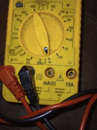
NOT using a pair of Probe Leads directly coming from the DMM to take Measurements RIGHT AT the Disconnected Component's Contact Pins...
View attachment 113729View attachment 113730
The Best Practices for the uses of any DVOM, any DMM or any Oscilloscope is to either Actively Back-Probe the Outside
(Back Side) of the Electrical Connectors between the Light Green Weather-Packing and the various Color ID'd Plastic Wire Insulation using Pin Probes like these depicted for inexpensive purchase over on Amazon, by passing them closely alongside the Weather-Pack Sheaths you can get the Thin Metal Probes into Direct Contact with the individual Wire-To-Pin interfaces deep inside of these Connectors...
View attachment 113735View attachment 113733
View attachment 113732View attachment 113734
View attachment 113716View attachment 113717View attachment 113718
...or... As an alternative technique, use instead, Direct Wire Probes that literally Penetrate the Wire Insulation in order to access the shielded Copper Wire and make a VERY Direct Circuit Connection on LIVE or STATIC Systems that MUST have the Component Connectors properly installed on the Vehicle. These are usually of a "Puncture and Screw Down TIGHT" Style of Wire Harness Probe.
View attachment 113719View attachment 113731
View attachment 113720View attachment 113721
In the Case of either making Low Amperage Measurements with a Loop Fuse Replacement or via Fuse Buddy Replacement Inserts or via Re-Settable Fuse Switches that stand in for the inconvenient Fuses that will quite often Burn Out during Testing...T
HESE are Very Convenient Temp Replacements:
View attachment 113724View attachment 113725
View attachment 113722View attachment 113723
Lastly, for the indirect sensing of High Voltage Circuits, such as on COP (Coil Over Plugs) or when Diagnosing the Wave Forms of Spark Plugs and picking their signals up via a Lead Clamp, there are Paddle Probes that can function without the need to make direct contact with the Circuit to sense their High Energy Electrical Fields of the Primary and Secondary Coils... and thus... Never have to open or touch these High Energy Circuit Components:
"Best Results can often be SEEN ...Whenever Viewed ...on an Oscilloscope SCREEN..."
View attachment 113726View attachment 113727View attachment 113728
 gmtnation.com