Just hooked up my old reader and am getting a p0340 circut ground . Followed the wires in the harness from the cam sensor to the pcm and could not find any breaks shorts in any of the 3 wires. I've replaced the pcm and pigtail. The computer was replaced with 1 from a junk yard at some point before I bought this vehicle. Any suggestions as to what else I could check ?
You are using an out of date browser. It may not display this or other websites correctly.
You should upgrade or use an alternative browser.
You should upgrade or use an alternative browser.
NEED HELP P0340 camshaft sort circut
- Thread starter DaveK
- Start date
Just hooked up my old reader and am getting a p0340 circut ground . Followed the wires in the harness from the cam sensor to the pcm and could not find any breaks shorts in any of the 3 wires. I've replaced the pcm and pigtail. The computer was replaced with 1 from a junk yard at some point before I bought this vehicle. Any suggestions as to what else I could check ?
You used an electrical test meter for these tests of the wires??
A visual check in not adequate for these purposes.

You used an electrical test meter for these tests of the wires??
A visual check in not adequate for these purposes.
I am getting a full 12 volts to the cam sensor. Haven't used a volt meter in years (I know it's fairly easy) how would I know if it's the ground wire and which color is the ground ? What would I set the meter on ? Like I said earlier....haven't used a meter in years and am out of practice.
I am getting a full 12 volts to the cam sensor. Haven't used a volt meter in years (I know it's fairly easy) how would I know if it's the ground wire and which color is the ground ? What would I set the meter on ? Like I said earlier....haven't used a meter in years and am out of practice.
I checked several years wiring diagrams, and I am assuming yours is a 6 cylinder engine, and I see RED is 12 volts, PINK/BLACK is low reference, and BROWN/WHITE is the signal wire.
When you tested for 12 volts did you test from RED to engine/frame ground or did you test to the low reference wire (PNK/BLK) ?
First...yes...it's a 6 cyl. I believe it WAS the red, but I could be wrong as it was awhile ago I checked. Which would I check for the ground fault ?
First...yes...it's a 6 cyl. I believe it WAS the red, but I could be wrong as it was awhile ago I checked. Which would I check for the ground fault ?
So you have mentioned "ground fault" a couple of times now. The code P0340 does not indicate a particular fault such as ground, power, or whatever. That P0340 code only indicates that for a specified time period the PCM saw no pulses coming from the sensor. It doesn't know why. So the fault could be power, ground, signal wire or even a dead sensor.
I would look at the voltage between the RED wire and the PINK/BLACK wire to start with.
None of those 3 stated possibilities conclude that a ground fault exists. An open circuit of the sensor signal wire (brn/white) would not involve a ground. A short to VREF doesn't involve a ground. The remaining possibility would mean the brn/wht wire is shorted to ground.
Your scantool is not a General Motors product and contains a generic interpretation of the code. They are giving you just some of the possibilities.
Here is some information taken directly from a general motors website stating the conditions for that code to set...

Your scantool is not a General Motors product and contains a generic interpretation of the code. They are giving you just some of the possibilities.
Here is some information taken directly from a general motors website stating the conditions for that code to set...
Ok. Acceptable. The camshaft sensor is brand new...a second brand new 1 I installed. Next question. What route should I take to attempt to resolve this issue ? Now I'm totally unsure what my next move should be. Clean the connections at the computer ? Replace the computer ? Do a relearn on the computer ? As stated in a previous posting, the computer was replaced with 1 from a junkyard before I bought the truck.
What brand of sensor did you use?? I cannot speak from personal experience here but I have read several times that this particular sensor is best to use AC Delco?? I have read of others trying house brand parts and have them not fix the issue where an AC Delco brand did fix the problem.
Does the code come back immediately after clearing or does it take more than a few drive cycles??
An intermittent electrical issue is frequently troublesome to nail down. That's because if the trouble isn't there all the time then it might not be there while you are testing of course! Makes it hard to find. I prefer troubles that are always there,,,, easier to find them.
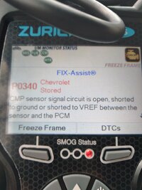
Looking at your photo,,, I see a button for "Freeze Frame". Have you checked in there? It might yield some clues,,, maybe. Also I see that scantool reports this as a "stored" code. I'm not sure what they mean by that. I am familiar with Current, Pending, MIL, History, Old, and 2 levels of manufacturer status, but not "stored". [ Of course it's stored!! How else could you read it out !  ]
]
There is a code status that means the code set once before but it is not currently happening and will eventually be deleted after a given number of drive cycles.
]There is a code status that means the code set once before but it is not currently happening and will eventually be deleted after a given number of drive cycles.
I believe bother were the generic. As for when the code comes.back...I can reset the check engine light , but as soon as I shut the vehicle down and re start it throws the same code again. I'm nearing my wits end on what to try next. I recently purchased a tech 2 scanner (specifically for GM vehicles) , will be turning to that as soon as I can get a laptop with xp to run updates (the tech2 won't work with higher than xp). Hopefully that'll give me more clarification.
A Bit More Diagnostic "Step-By-Steps" Advice. It will be important to READ EVERYTHING on BOTH Page 1 AND Page 2 before proceeding:
 troubleshootmyvehicle.com
How To Test Camshaft Position Sensor (2002-2005 4.2L Chevrolet Trailblazer)
Last edited:
Mooseman
Moderator
You don't need a laptop to run diagnostics. It's needed only for the more advanced stuff like reprogramming modules and getting security access.
I would do a continuity test of each wire from the sensor to the PCM. Download the manual (link in my signature) for the schematics.
I would do a continuity test of each wire from the sensor to the PCM. Download the manual (link in my signature) for the schematics.
I apologize if I am hijacking this thread.
I am having a P340 issue also. I did the DMM test in the link above, and the results are not clear. I disconnected the plug from the cam sensor, probed red wire to batt neg: 11.89vdc. I probed pink wire to batt pos: 11.89vdc. I reconnected the plug and disconnected all 6 ignition coils. I back probed the brown (center) wire at the sensor plug with pos meter lead. Neg meter lead to batt neg. I turned ignition switch on, and meter read 9.42vdc. I rotated the engine crankshaft 3 full revolutions and meter read constant 9.42vdc, never changed. I replaced cam sensor, reconnected the coils, reset the code and started and stopped the engine 3 times. 3rd time, P340 came back. I redid the whole test procedure again, with exactly the same results on the new sensor. The only difference was center wire read 9.37vdc constantly. I have zero idea where to go next.
Car is 2004 GMC Envoy XUV, 4.2L 4wd.
Thanks in advance,
Billy
A Few Things before we "Roll Tape" on @MAY03LT running though his Diagnostic Procedures for a P0340 Code:
(1) ALWAYS Choose ACDelco OEM Replacement Parts over ANY Other After-Market Brand:

(2) Even though Drew was unable to demonstrate what the Oscilloscope Screen was showing in "Real YT Time" as "Three WIDE and Three NARROW Square Wave Patterns" to the Viewers... Trust Me... The ONLY WAY to be able to see any Error happening at the FAST "Rate of Change" the CPS Sensor and Computer perform during Square Wave Generation is to use either a Hantek Model# 1008C (8) Channel Oscilloscope...or a PICO-Scope Model# 2204A (2) Channel Oscilloscope connected to your Laptop Computer and viewing the Errant Wave Forms that Drew Hand Draws Out On PAPER after he sees the problem ON SCREEN.
(3) Recommended Homework:
 gmtnation.com
On With The Show...
Thanks to @MAY03LT for this YouTube Video and HIS Screen Cap of a KNOWN GOOD CPS WAVE FORM after changing the OEM Bad CPS for a Brand New ACDelco CPS:

And in THIS arguably 'Better' Video... "The Car Doctor" actually performs THIS Exact Same Oscilloscope Diagnosis of the P0340 and P0172 Codes by showing you the By The Book, Step-By-Steps in How To DO This Examination.
Take Note that the SAME ERRANT CPS KNOWN "BAD" WAVE FORM Patterns Drew found and Documented are also present in Plain View in THESE KNOWN GOOD vs. KNOWN BAD CPS Wave Form Screen Caps:
KNOWN GOOD CPS WAVE FORMS:


KNOWN BAD CPS WAVE FORMS (Sets The P0340 Code):


Screen Caps taken from THIS Video:
A Decade after @MAY03LT recorded his Video, EZ-2-USE Automotive Oscilloscopes have FINALLY become Affordable!
(1) ALWAYS Choose ACDelco OEM Replacement Parts over ANY Other After-Market Brand:
(2) Even though Drew was unable to demonstrate what the Oscilloscope Screen was showing in "Real YT Time" as "Three WIDE and Three NARROW Square Wave Patterns" to the Viewers... Trust Me... The ONLY WAY to be able to see any Error happening at the FAST "Rate of Change" the CPS Sensor and Computer perform during Square Wave Generation is to use either a Hantek Model# 1008C (8) Channel Oscilloscope...or a PICO-Scope Model# 2204A (2) Channel Oscilloscope connected to your Laptop Computer and viewing the Errant Wave Forms that Drew Hand Draws Out On PAPER after he sees the problem ON SCREEN.
(3) Recommended Homework:
How To Use PICO #2204A & HANTEK #1008C Oscilloscopes
You don't need a Huge Bag of Coins in order to obtain and use an Oscilloscope for performing In-Depth Wave Form Analysis in Automotive Applications on everything from Problematic Electronic Fuel Injection to obtaining accurate Compression Tests to Diagnose Internal Engine Conditions. HANTEK...
On With The Show...
Thanks to @MAY03LT for this YouTube Video and HIS Screen Cap of a KNOWN GOOD CPS WAVE FORM after changing the OEM Bad CPS for a Brand New ACDelco CPS:
And in THIS arguably 'Better' Video... "The Car Doctor" actually performs THIS Exact Same Oscilloscope Diagnosis of the P0340 and P0172 Codes by showing you the By The Book, Step-By-Steps in How To DO This Examination.
Take Note that the SAME ERRANT CPS KNOWN "BAD" WAVE FORM Patterns Drew found and Documented are also present in Plain View in THESE KNOWN GOOD vs. KNOWN BAD CPS Wave Form Screen Caps:
KNOWN GOOD CPS WAVE FORMS:
KNOWN BAD CPS WAVE FORMS (Sets The P0340 Code):
Screen Caps taken from THIS Video:
A Decade after @MAY03LT recorded his Video, EZ-2-USE Automotive Oscilloscopes have FINALLY become Affordable!
Last edited:
Your testing seems relatively good BUT...I apologize if I am hijacking this thread.
I am having a P340 issue also. I did the DMM test in the link above, and the results are not clear. I disconnected the plug from the cam sensor, probed red wire to batt neg: 11.89vdc. I probed pink wire to batt pos: 11.89vdc. I reconnected the plug and disconnected all 6 ignition coils. I back probed the brown (center) wire at the sensor plug with pos meter lead. Neg meter lead to batt neg. I turned ignition switch on, and meter read 9.42vdc. I rotated the engine crankshaft 3 full revolutions and meter read constant 9.42vdc, never changed. I replaced cam sensor, reconnected the coils, reset the code and started and stopped the engine 3 times. 3rd time, P340 came back. I redid the whole test procedure again, with exactly the same results on the new sensor. The only difference was center wire read 9.37vdc constantly. I have zero idea where to go next.
Car is 2004 GMC Envoy XUV, 4.2L 4wd.
Thanks in advance,
Billy
 when you say you rotated the engine 3 times... how did you do that? You have to do this (rotate the engine) by hand "slowly" as a dmm's output won't be correct / what you are looking for otherwise. That is why the subsequent post showing wave forms was posted as help. As you can see, there IS a wave form and not a constant dc voltage which a normal meter is expecting to measure. Hence, most meters will try to do an "RMS average" of the signal which it appears that yours is doing... thus the lower "DC value".
I used a socket and ratchet. Very slowly. I'd guess 1 rpm??? Meter never changed with either sensor.Your testing seems relatively good BUT...
I'm working on borrowing a scope. Hopefully I will have it today.
Buying one right now is out of the equation. I've spent over a grand on this car so far this year. 3/4 clutch pack was toast and ignition coil went out. Now its cam sensor and fan clutch.
While playing "The Joker" in Tim Burton's "BATMAN"... Jack Nicholson blurted out, "Never Rub Another Man's Rhubarb!" and by imitation, I'll add in, "...and Never Spend Another Man's Money...". I promise not to try.
Nonetheless... Just be aware that You can literally 'Buy the Whole Base Hantek Oscilloscope with Probes, Cables Kit & Caboodle' for right around $100.00 via Amazon and then use your Laptop in concert with all of this VERY Cool Gear to definitively figure out your present dilemma ...and so much more besides:


@MAY03LT proved in his Video that even if you use a "GYMKO" Tech 2 in concert with any other DMM that does NOT bear the Name "FLUKE" and cost several thousands, you STILL won't be able to Capture the Pulse Width Modulated and Electrical Signals in real Time as they carry on their "Visual Chit-Chat" in ways that will allow you to SEE and UNDERSTAND precisely WTF is REALLY Going On.with EVERYTHING inside that makes your Vehicles Work (or NOT).
None of us begins this Journey knowing ANYTHING about what an Oscilloscope brings to Modern Automotive Diagnostics. Admittedly, at first, it can be a little intimidating ... but not for long if one uses all of the YouTube Videos and FREE Automotive Diagnostic Software. Just by using this Gear... Understanding HOW it Works and How to THINK "Oscilloscopically" will come on very quickly afterwards.
Nonetheless... Just be aware that You can literally 'Buy the Whole Base Hantek Oscilloscope with Probes, Cables Kit & Caboodle' for right around $100.00 via Amazon and then use your Laptop in concert with all of this VERY Cool Gear to definitively figure out your present dilemma ...and so much more besides:
@MAY03LT proved in his Video that even if you use a "GYMKO" Tech 2 in concert with any other DMM that does NOT bear the Name "FLUKE" and cost several thousands, you STILL won't be able to Capture the Pulse Width Modulated and Electrical Signals in real Time as they carry on their "Visual Chit-Chat" in ways that will allow you to SEE and UNDERSTAND precisely WTF is REALLY Going On.with EVERYTHING inside that makes your Vehicles Work (or NOT).
None of us begins this Journey knowing ANYTHING about what an Oscilloscope brings to Modern Automotive Diagnostics. Admittedly, at first, it can be a little intimidating ... but not for long if one uses all of the YouTube Videos and FREE Automotive Diagnostic Software. Just by using this Gear... Understanding HOW it Works and How to THINK "Oscilloscopically" will come on very quickly afterwards.
Last edited:
hmmm.... I re-read your testing post. Quote: "...probed red wire to batt neg: 11.89vdc. I probed pink wire to batt pos: 11.89vdc...." the red wire test is clear but the pink wire test isn't ... did you switch meter probes around? If so, then OK otherwise I would have expected a -ve reading.I used a socket and ratchet. Very slowly. I'd guess 1 rpm??? Meter never changed with either sensor.
I'm working on borrowing a scope. Hopefully I will have it today.
Buying one right now is out of the equation. I've spent over a grand on this car so far this year. 3/4 clutch pack was toast and ignition coil went out. Now its cam sensor and fan clutch.
Further, your test with key on and the brown wire showing only 9.x voltages.... I think that you need to do that test with meter ground lead on the "low ref" lead. Then again with the rotation. You might have some form of grounding issue that is impact low ref... maybe.
One more thing to try... with key off, do a resistance measure from the pink to ground to check the electricals around the "low ref".
still further, you might be able to simulate a "cam" by having the sensor hanging in "free space" and passing a chunk of steel past the sensor and monitoring the voltage as you were doing.
Last edited:
To provide some clarity as to WHY the Correct Known Good Wave Form displays Three symmetrically WIDE and Three symmetrically NARROW Hall Effect Square Wave Signals... observe the distribution of the "Notches" cut into the outer orbit of the "Reluctor-Wheel" like design of the Early Model Delphi Cam Phaser:

The "By The Book" Diagnostic Actions (Courtesy "The Car Doctor" YT Video above):

The CPS Device picks up the Magnetic Inductance as the Cam Phaser Steel Notches Rotate past it and thus, alerts the PCM as to the ABSOLUTE Position of the Exhaust Cam Lobes of the #1 Cylinder for comparison against the Variable 0-25 Degrees of Exhaust Cam Retard made possible by the actions of the CPAS Solenoid.
In combination... these Two Different Exhaust Cam Sensors allow the PCM to know how to take the best advantage of the Engine RPM vs. Torque Curve and provide the GM 4.2L Engine with a VERY wide range of Power and Performance. At Low RPM they also act together in much the same way as an EGR Unit.
But if the CPS Unit is BAD... None of these actions can occur.
The "By The Book" Diagnostic Actions (Courtesy "The Car Doctor" YT Video above):
The CPS Device picks up the Magnetic Inductance as the Cam Phaser Steel Notches Rotate past it and thus, alerts the PCM as to the ABSOLUTE Position of the Exhaust Cam Lobes of the #1 Cylinder for comparison against the Variable 0-25 Degrees of Exhaust Cam Retard made possible by the actions of the CPAS Solenoid.
In combination... these Two Different Exhaust Cam Sensors allow the PCM to know how to take the best advantage of the Engine RPM vs. Torque Curve and provide the GM 4.2L Engine with a VERY wide range of Power and Performance. At Low RPM they also act together in much the same way as an EGR Unit.
But if the CPS Unit is BAD... None of these actions can occur.
Last edited:
Ok, I wasn't able to borrow the scope yet, but I did test some more.hmmm.... I re-read your testing post. Quote: "...probed red wire to batt neg: 11.89vdc. I probed pink wire to batt pos: 11.89vdc...." the red wire test is clear but the pink wire test isn't ... did you switch meter probes around? If so, then OK otherwise I would have expected a -ve reading.
Further, your test with key on and the brown wire showing only 9.x voltages.... I think that you need to do that test with meter ground lead on the "low ref" lead. Then again with the rotation. You might have some form of grounding issue that is impact low ref... maybe.
One more thing to try... with key off, do a resistance measure from the pink to ground to check the electricals around the "low ref".
still further, you might be able to simulate a "cam" by having the sensor hanging in "free space" and passing a chunk of steel past the sensor and monitoring the voltage as you were doing.
Cam sensor out of engine.
Negative meter lead back probed pink low ref wire, positive meter lead back probed brown signal wire. Key on. Voltage read 9.87vdc. I passed a 25mm deep socket across the sensor one pass, voltage went to 0.01vdc. I passed the socket across the sensor again, voltage went to 9.87vdc. Multiple passes, same results. The voltage would hold until next pass, alternating from 9.87vdc to 0.01vdc back to 9.87vdc...etc.
I tried it again with the old sensor. It also read the same as the new one.
Reinstalled the new sensor in the engine. Slowly rotated the engine....no sensor change in voltage.
So, I wondered if the cam was turning. I used an inspection camera and looked into the sensor hole. I could see the notches in the phaser. It looked like cast iron or cast steel. Seemed pitted to me, but it did turn when I turned the crank.
Last edited:
good work.... another things that you can try is a "dropped screw magnet" .... ie. its a small magnet on the end of rod... its used to pick up screws and such from hard to reach places / dropped in cavities, etc... You can then put it into the hole where sensor is place and get a feel for how much attraction there is on the cam... maybe its corroded for some reason resulting in little to no attraction. Further, use a stick or otherwise and measure the distance of how far down the cam sprocket is in the hole. Compare that to the sensor body... maybe the sensor is not seating properly.
I did a quick measurement. From the edge of the sensor hole to the cam sprocket, I measured 26.63mm. Cam sensor measures 26.13mm. I wont guarantee that I am 100% accurate but it's very close. I probed with a wooden dowel and marked the dowel with a sharp pencil. Then I measured my mark with a digital caliper.
I will do the magnet test tonight.
I will do the magnet test tonight.
Paul "Scanner" Danner's Brother, James Danner, is also an Expert Diagnostician-Mechanic Cut from the Same Cloth by his use of an Oscilloscope (...actually TWO in this Example) while hunting down an Trailblazer's 4.2L Engine Running Raggedy as HELL and Misfiring.
The important connection to what your situation is that he BACK-PROBES THE CPS ALONG WITH THE CKP Sensors in order to compare their "Timing" Line Ups (or Mis-Alignments) as they share the SAME Oscilloscope Screen.
Eventually... he performs an R&R replacement of the CPAS Solenoid, once he discovers that the installed GM OEM CPAS had 'burped out' its S/S Filtration Screens and one got JAMMED sideways inside of the CPAS Sliding Hydraulic Oil Pressure Powered Piston.
Take notice that even though his On-Screen Wave Forms look a lot W-I-D-E-R than the Exemplars shown in Post #16 ...they still have those identical THREE WIDE & THREE NARROW HALL EFFECT PATTERNS:
This is just an added example of 'How to Use an Oscilloscope' involving the same CPS Unit you are concerned with, using a DIFFERENT Oscilloscope ...but for slightly different Diagnostic Reasons.
I dont want to jinx myself, but I believe I have fixed it!
I got to thinking about holding the sensor in my hand and it working vs in the engine not working. When I held the sensor, the wires were straight, and in the engine they were curved around 180°.
I cut the connector wires off about 6" back from the sensor. Temporarily, I soldered wires directly to the terminals of my old sensor, filled the cavity of the sensor with hot glue to insulate the connection. Then I soldered the wires back together where I cut them.
I socket tested the sensor, alternated 9.87vdc to 0.01vdc and back to 9.87vdc.
Re installed sensor, key on, turned crank and bam! Alternating 9.87vdc to 0.01vdc back to 9.87vdc.
Reset code, restarted car multiple times. And test drive it 20 or so miles.
P0340 is GONE.
Thanks to all. Especially Budwich. He got me to thinking with common sense instead of scatter brains.
Mooseman
Moderator
the great part about this, is perhaps your effort may help the OP with his problem which he never appears to have returned to advise.I dont want to jinx myself, but I believe I have fixed it!
I got to thinking about holding the sensor in my hand and it working vs in the engine not working. When I held the sensor, the wires were straight, and in the engine they were curved around 180°.
I cut the connector wires off about 6" back from the sensor. Temporarily, I soldered wires directly to the terminals of my old sensor, filled the cavity of the sensor with hot glue to insulate the connection. Then I soldered the wires back together where I cut them.
I socket tested the sensor, alternated 9.87vdc to 0.01vdc and back to 9.87vdc.
Re installed sensor, key on, turned crank and bam! Alternating 9.87vdc to 0.01vdc back to 9.87vdc.
Reset code, restarted car multiple times. And test drive it 20 or so miles.
P0340 is GONE.
Thanks to all. Especially Budwich. He got me to thinking with common sense instead of scatter brains.
Mooseman
Moderator
Which, alas, is what happens a lot here.the great part about this, is perhaps your effort may help the OP with his problem which he never appears to have returned to advise.