Let the fun begin...pulled the head on my 4.2L

Status
Not open for further replies.

midnightbluS10

Original poster
Member
Feb 18, 2017
104
Shreveport, LA
I have a problem. I torqued the head bolts to the proper specs and left for lunch. When I returned, I noticed the red Permatex assembly lube I used on the valvetrain is now pushing out from between the head and block, all the way around the head. It's enough that it's visible in the parting line between the head and block but not leaking down the sides of the block except in the rear.

At this point, I'm guessing I'll be pulling the head and buying new bolts, at least to make sure the surfaces and gasket are clean and dry. They were when I put the head on the block. And the assembly lube should've drained through the drainback holes into the oilpan/catch pan under the engine.

So how did it end up between the head and block? I'm clueless on this. Anyone got any ideas?
 

mrrsm

Lifetime VIP Donor
Supporting Donor
Member
Oct 22, 2015
7,727
Tampa Bay Area
Wow… Justin... Brother... Jesus Wept...

The answer to your inquiry depends upon the "Orders of Operation" that you followed when applying the Red Assembly Lube to the components on the Valve Train... and these actions might cascade as follows:

(1) If you applied the Red Assembly Lube to the Valve Train Components BEFORE lowering the Engine Head onto the Engine Block and accidentally allowed the Thick Lubricant to drop or dribble down inside the 14 Large Head Bolt Holes... then the fluid could have drained all the way down into the bottom of the Blind Bolt Holes inside of Engine Block… thereby leading to the Next Problem...

(2) All Liquids… especially thick, viscous fluids particularly designed to resist Very High Pressures are virtually… incompressible. So if the Red Assembly Lube had managed to drain down into the bottom of the Blind Holes inside of the Engine Block, then as soon as the M11 X 2.00MM Head Bolts achieved enough wind-down to form a contact thread seal inside each Bolt Hole...the Incompressible Red Assembly Lube would begin to fight back against being “Squeezed”/ And while the Fluids themselves would remain unharmed... the pressures they can exert can rise to Several Thousands of PSI very quickly. If the compartmentalized Red Lube could not bleed off these incredible pressures being exerted during the TTY final Torque Angle phase of Bolt Tightening and escape around the 10.9 Grade 8 Bolt Threads to soft Aluminum Engine Block Bolt Hole Cavities… they could either strip the entire thread line right out of the Engine Block Bolt Holes as they push upwards against the bottom of the Bolt End ...just like Butter… or cause the Bolt Holes in the top of the Engine Block to crack open like Walnuts being hit with a Nine Pound Sledge Hammer…. Which leads to the Next Problem...

(3) Any residual Red Lube nested under the nose of the Head Bolt could be squeezed upwards around the shaft of the Bolts and since there would be no more binding or holding force in the relationship between the Screw Cap of the Bolt holding down the Engine Head… then the space between the Engine Block and the Engine Head would be loose enough to allow the Red Lube to ooze upwards and outwards along the margins in between where the MLS Gasket resides...and decorate the margin line ...with Red Assembly Lube… just like a Grease Gun works on a Zerk Fitting of a Ball Joint.

But until you tear things back down and examine each and every thing as it is being removed… you won’t know this for certain and if you are SURE that you applied the Red Assembly Lube to the Valve Train AFTER installing, torquing and using the correct TTY additional torque angle on the Head Bolts… then the suspicious presence of any Red Assembly Lube being down inside of the Engine Block Bolt Holes is strong evidence that this action may have to have been done maliciously by someone else.

I know it is difficult to imagine anybody contemplating such an horrendous act of sabotage… but if others in your Training Class had access to the Open Engine Block during this work… just keep this idea in the back of your mind as you perform the Autopsy. Lets hope that if any... the least amount of damage has occurred and that you can come up with a better cause and origin of the Mysterious Red Line that makes sense. It would be best to look the entire matter over very carefully after the tear down & inspection and avoid jumping to the worst case conclusions. If you can take some images and post them back here… I am sure we’d all like to see what happened here… first hand.
 
Last edited:

midnightbluS10

Original poster
Member
Feb 18, 2017
104
Shreveport, LA
All the bolt holes were clean and dry until I used a very, very light coating of arp ultra-torque bolt lube on the threads and on the washer per their recommendation of taking 2 bolts and using the threads to spread it around and into the threads of both bolts, then wiped off any excess, of which there was very little.

None of this should have caused any sort of mechanical malfunction or catastrophic failure or the bolt holes. Still, the engine assembly lube wasn't anywhere close to the holes. That's why this doesn't make sense to me.


I used the Permatex Ultra Slick assembly lube on the head while it was on the workbench, before I set it on the block. After I put it on the block, I dabbed a small drop on each cam lobe and that was it. Ughhh. I made sure each bolt hole was still clean and dry before I installed the bolts so I'm sure there wasn't any lube accumulated in the holes.

Being that these are TTY bolts, and knowing how the arp lube works, it doesn't make sense that it would cause the bolts to not put the correct clamping load on the head. That's what it's for. It removes the friction and allows the clamping force and bolt stretch to be what determines torque/clamping load and not bolt friction. It makes it so you get a true reading from the bolt stretching to yield instead of working against the forces of friction and not reaching its yield point.

Is it possible the bolts aren't clamping as tight as they should for some reason, you think? But that still wouldn't explain how the Permatex Ultra Slick engine assembly lube got to the headgasket and then squeezed out between the block and head.

I guess it's possible I put the headgasket on upside down and the drain holes are blocked but I doubt it. Hmmm.

Either way, I have to buy new head bolts, don't I? I'm guessing the cam sprocket bolts are ok unless I need to remove them, also.

Speaking of the cams, I rotated the engine through and it took 14 revolutions to get it back in time. Is that correct? I thought I read 13?


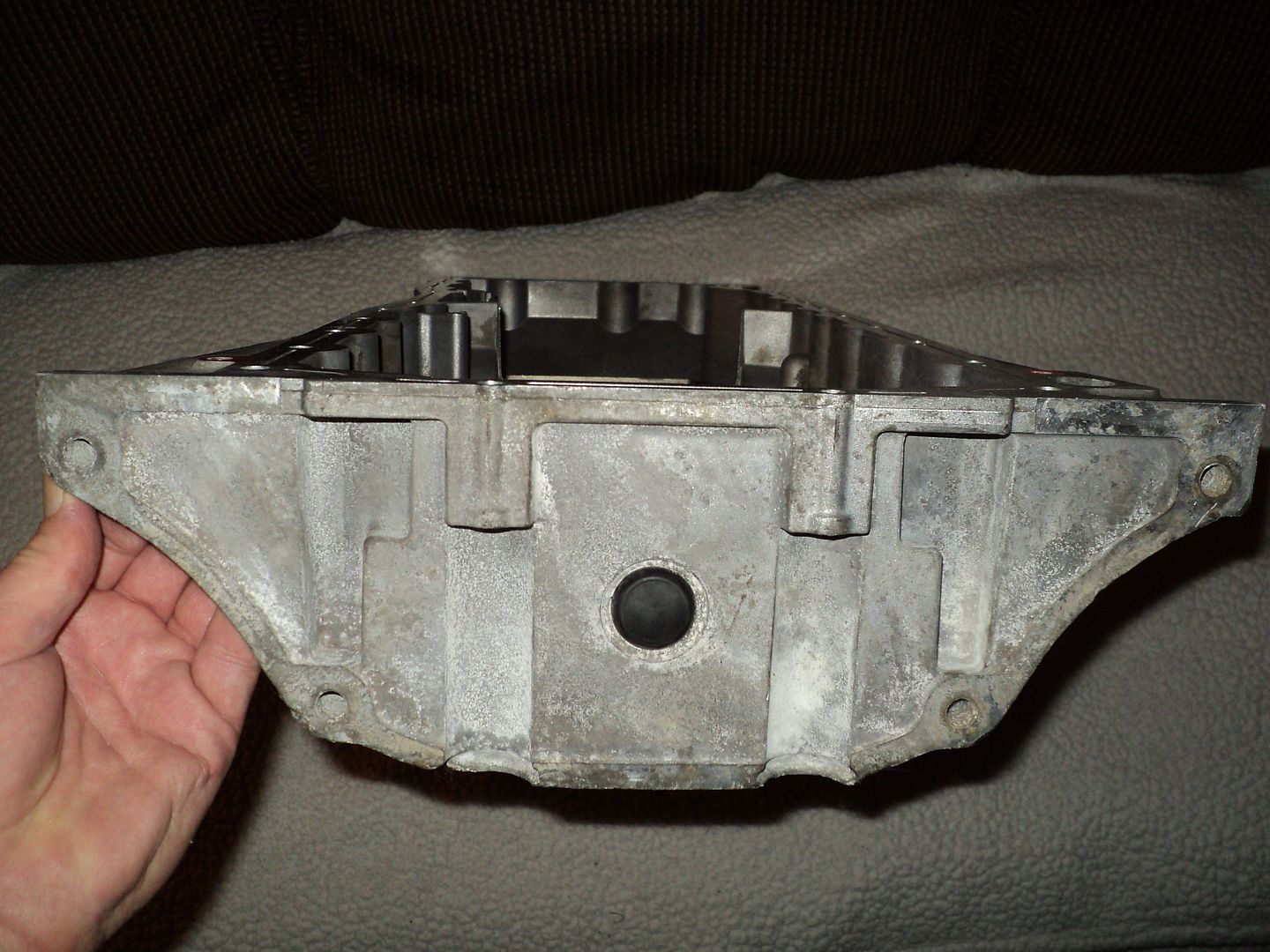
Edit: I did just remember that at one point, the engine was cocked at about a 5* angle on the engine stand, as if someone started to rotate it over 180* to install the oil pan, for example, and stopped. Maybe that caused the assembly lube to possibly leak down the walls of the oil drain back holes, and into the parting line between block and heads? It wasn't bolted down at that point. I just remembered this.

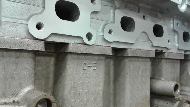
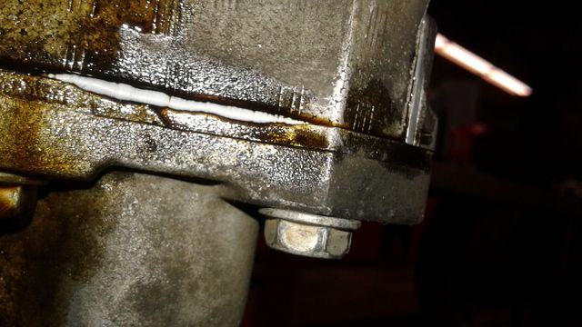
None of it was visible in the parting line until I got the head torqued down. So it had to be accumulated on the headgasket and/or below it on the block and was squeezed out when I torqued it down, I would think.


This is the kind of stuff I run into when I'm on a deadline. Things no one has ever heard of. Class ends in 2 weeks and we just missed the last 3.5 weeks due to the instructor being out sick and a week for Spring Break. He's still not back. They had a guy that just graduated come substitute. Yesterday, he said the guy probably won't be back.

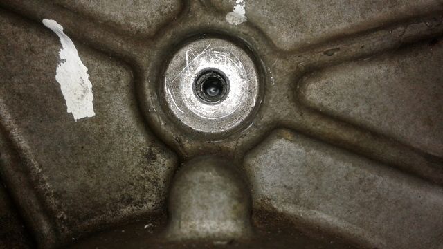
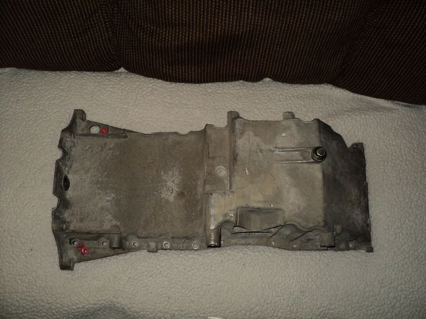
Sorry this is so long. I've edited it 4 or 5 times to add information as I remembered it. So here's the obligatory visual reference. I got a few pics of all 4 sides.

 
Last edited:

Mooseman

Moderator
Dec 4, 2011
25,341
Ottawa, ON
If you are certain that there was no excessive amount of lube in the bolt holes, I wouldn't worry about it. Probably a little lube got on the head surface and it just got squished out. I know these are supposed to be installed dry but the lube shouldn't do anything to the gasket's sealing ability.

Oh, and it's impossible to install the gasket upside down. Think about it...
 
  • Like
Reactions: Capote

mrrsm

Lifetime VIP Donor
Supporting Donor
Member
Oct 22, 2015
7,727
Tampa Bay Area
There is one other possible place where the Red Goo could have come from ...and that would be if any of the stuff was used to lubricate the walls of all the cylinders and have enough of the stuff present when you did your 13 Rotations to meet the Red Lube at TDC Xs (6) and uniformly, while trying to hydro-lock the stuff … the Pistons may have managed to squeeze the red material out along the margins of the Combustion Chambers as each rotation was completed. After completing that “unlucky” number of rotations… perhaps it would explain its uniformity around the perimeter edges of the Head-to-Block seam.

Because you have already had to struggle with enough difficulty and set-backs… I am loathe to suggest these considerations in favor of an R&R… New head Gasket and New Bolts and “Wash, Rinse Repeat...”. The idea though ultimately is that if the Head Gasket Leaks and Coolant goes where it should not...and Oil goes where it should not… the complications that would follow of having to do this work AFTER the Engine has been installed inside the SUV becomes a heavier burden to bear, indeed.

Here are some Pros for re-doing the Engine Head-MLS Gasket R&R

(1) The Engine is on the Stand right now and easily accessible for inspection and ease of finding out exactly what went wrong… and the R&R of the Head is a Breeze.... now.

(2) The Head Bolts have already loosened… even if just a tiny bit while you were at Lunch and then came back to find that the clamping force had squeezed out the Red Goo. The subsidence might be enough to cause the Head Gasket to leak already.

(3) Even Though the MLS Gasket is supposed to be made of inorganic steel… it is still coated with the Oil and Water Jacket DuPont Viton PTFE Isolation Sealant that may have been loosened or rendered ineffective due to the presence of the Red Lubricant.

(4) Once you “Put the Music To It” and the engine is up and running… the Red Lube is going to be exposed to High Head Temperatures that may cause it to boil, expand and vaporize in between and perhaps form escape channels inside the Viton Gasket coatings and allow the Head Gasket to fail as a result.

(5) For the sake of your own Peace of Mind… even if it turns out to be some strange residue that never actually got close enough to cause any problems… If you do not pull the Head off of the Engine Block...you won’t know for certain… and from the moment you start and run the Engine… that worry will be unending while you wait to see if a Damned MLS Head Gasket failure is still looming.
 
  • Love
Reactions: 808

midnightbluS10

Original poster
Member
Feb 18, 2017
104
Shreveport, LA
I didn't put any assembly lube in the cylinders. Only clean engine oil. That's why this has me so stumped. I'll be back there on Monday to disassemble and inspect everything.

Gotta go get new head bolts, cam bolts, and a headgasket unless it's reusable. Not looking forward to doing the timing again, either. Ugh. This sucks.

It's bad enough I lost 3 weeks of work time. Now I've gotta redo all this stuff. Not looking g forward to it whatsoever.
 

midnightbluS10

Original poster
Member
Feb 18, 2017
104
Shreveport, LA
Got that taken care of. The entire top side of the gasket was covered in assembly lube. The underside only had a few small spots where it made it between the gasket and block. Replaced the headgasket and bolts and got it all torqued back down.

One thing I noticed was that some bolts didn't take as much force to get to the 155* as the others. Has anyone else noticed that?
 

Mooseman

Moderator
Dec 4, 2011
25,341
Ottawa, ON
I noticed that when I did it on my 5.3L. AFAIK, it's still good. Maybe that's why they went to degrees instead of just torque.
 

mrrsm

Lifetime VIP Donor
Supporting Donor
Member
Oct 22, 2015
7,727
Tampa Bay Area
This FelPro Instructional PDF is on the very subject about TTY (Torque To Yield) Fasteners and covers Three Possible Energy Vectors that can exist when tightening down such TTY Fasteners...and the implications of the resistance or lack thereof ...to be expected that will vary with all Three Conditions. Please pay particular attention to the colored Graph of the data:

http://www.felpro-only.com/blog/proper-installation-use-t-t-y-bolts/

If you check with one of our Members... @m.mcmillen (I call him "The Legendary Mac" because of his hard work and dedicated efforts at successfully rebuilding his own GM 4.2L LL8 Engines). While completely rebuilding his Motor... he managed to install a rebuilt engine head and after encountering some strangeness with using Dorman Head Bolts vs. the GM OEM variants... he replaced them dutifully with the OEM flavor and then loyally documented his procedures. These included a method to investigate the Final Torque feedback. If you PM him...he should be able to elucidate what he did to check out all 14 Large Head Bolts...and the methods he used to assure their uniformity of TTY tightness. ;>)
 

midnightbluS10

Original poster
Member
Feb 18, 2017
104
Shreveport, LA
Thanks for the reply. I saw that page in my searching and read of one guys that asked the same question to them, explaining that his digital snap-on wrench showed final torque and most were similar except for a few that were a little less. I 3ven started to reference it in my previous post, but decided to omit that part.

I'm thinking a beam type torque wrench would work to show what each bolt is currently at, or what it takes to break loose. Or at least tighten until it moves the slightest amount and note the figure shown at the pointer.


Here was that guys question and felpro's reply:


Mark@felpro said:
I’m replacing the head on a 2003 Trailblazer. I cleaned all of the bolt holes out and chased the threads so everything is clean inside. I am using a Snapon digital torque wrench that measures angle and when the angle is done, it will tell me the final torque. All of the bolts except for 3 measured in the 70-75 foot pound range. Two of the bolts across from each other measured 53 foot pounds and one other measured 99 foot pounds. Should I be worried about this? I didn’t put any lubricant on the bolts. I did put a little under the head of the bolt.

Reply
  1. Fel-Pro-Blog-Team_avatar_1409254330-44x44.png
    Fel-Pro Blog TeamOctober 14, 2016 at 12:31 pm
    Hi Mark,

    Thanks for your patience while we looked into this!

    Depending on which bolt is compressing different areas on a head & head gasket, you will get some variance in the final torque reading with the method you used. When using a clicker type torque wrench the bolt will just keep turning until it reaches that torque. In this case where the bolts are TTY, most installers are not measuring the final torque, they are just turning the bolt the specified amount of degrees. Sometimes the bolts in the center of a joint with multiple fasteners will have a lower final torque than the outer bolts. This is the gasket settling into place.

    Remember that a torque wrench is measuring friction. The threads and bolt heads have a tremendous amount of friction going on between them. The threads account for about 40% -45% of the friction and the bolt head uses up about the same. That’s why the condition of the threads, cleanliness of the threads, the type of lubrication, torque wrench calibration and the speed the bolt is being turned applied to the bolt has a huge affect on the torque being applied to the joint. TTY bolts takes some of things that can affect proper joint load out of the picture. Since the bolt is being turned a specified amount of degrees and not waiting for a clicker type torque wrench to click off due to friction, the joint receives the proper clamp load. If you have ever noticed that when installing a fastener to a specified torque, if you stop rotating the bolt before the wrench clicks off, when you start to rotate the bolt again, it does not move much. That’s because you are trying to overcome all the friction created by the threads & bolt head. It’s always best to continue to rotate the fastener continually until the wrench clicks off. This is not always possible when working in an engine bay.

    GM does not recommend applying any lube to these head bolts which is contrary to most head gasket installations. GM wants the bolts & block threads clean & dry for this installation. Applying some lube to under the bolt heads should not be an issue. So after this long-winded response, as long as you turned each bolt to the specified amount of degrees that GM specs out, you will be fine. The bolts that measured low or high may have something on them that would have contributed to a low or high torque reading.

    These bolts are TTY, So if you remove them, they would need to be replaced.

    Reply
 
Last edited:
  • Wow
Reactions: 808

m.mcmillen

Member
Apr 29, 2016
554
Wisconsin
Ok, funny thing here. That was me that asked the question and I gave up on the answer when the post that I made disappeared off their website!

I talked with the machinist that did rebuilt my cylinder head and he told me not to worry about it. So, I just moved on and everything is still working out great.

I did install the bolts dry with only some oil on the washer to allow the bolt head to turn freely.

When I was torquing my bolts, I wrote down what I got for torque on every bolt.
bolt torques.jpg

Also, @MRRSM, I didn't have trouble with not using OEM head bolts. It was the crankshaft main bearing bolts that I was questioning. I bought a set of main bearing bolts from the dealer and they all torqued evenly. The Dorman bolts were creaking and popping as I tightened them up. Even with a bit of oil on them.
 
  • Like
  • Love
Reactions: 808 and mrrsm

mrrsm

Lifetime VIP Donor
Supporting Donor
Member
Oct 22, 2015
7,727
Tampa Bay Area
That's Right... Forgive the mix up on my part... but it IS very Ironic that it would have been your own post at the Felpro PDF site that connects you to the OP's situation... What an interesting and serendipitous thing! ;>)
 

midnightbluS10

Original poster
Member
Feb 18, 2017
104
Shreveport, LA
Ran into another problem today. I snapped off the center, short bolt in the timing cover. Luckily, I was able to spin it out with a pick. I was tightening to 89 in.lbs and it kept going, never getting tighter. On the next pass, it snapped the head off.

See what I mean? It's always the stupid stuff that I run into. Lol. Time to make another trip to the dealership.

Last trip, on Monday, my '01 Blazer snapped the throttle cable at the pedal. Being that I was headed there anyway, I picked up another cable and swapped it in on the side of the road.

This is the 2nd one I've replaced. Last time, my pedal went to the floor while on the interstate going 70mph. I had to stand on the brakes with both feet to keep from plowing into someone. I didn't put it in neutral because my new engine only had 2k miles on it at the time. So I rode the brake as hard as I could until I got clear of traffic, then reached down and pulled up on the pedal and the cable snapped. Then the truck died and I coasted to the shoulder. This time, it just broke, like my foot slipped off the pedal and the pedal went to the floor and engine to idle speed.


Back to the issue at hand. Anyone got a part number for that center bolt? I've searched and can't locate it online. Haven't checked here, yet.

Thanks.
 
Last edited:
  • Like
Reactions: mrrsm

mrrsm

Lifetime VIP Donor
Supporting Donor
Member
Oct 22, 2015
7,727
Tampa Bay Area
That "Little Black Bolt" looks like it would not be very important...but it manages to align the Center of the Cover as a Rigid Structural Member, Don't forget to add a touch of AC Delco RTV, too.

Small Safety Issue H/J on the 2001 Blazer Throttle Cable Issue;

FWIW... Make a close examination of the proximity of any Large Stainless Worm Gear Clamp that secures the Intake Air Tube to the TB Air Inlet... as it might have been placed on the WRONG SIDE THE THROTTLE BODY and and wind up being directly in line with the Mechanical Throttle Body Linkage.

In some cases... upon acceleration by "Putting the Pedal to The Floor..." the rotating TB Bell Crank with the Advance and Return Cables threaded through them can be rotated and PUSHED PAST THE S/S SCREW HEAD OF THE CLAMP... AND BECOME TRAPPED IN THE WIDE OPEN THROTTLE POSITION. THIS WILL PREVENT THE ACTION OF THE WEAK RETURN SPRINGS OF THE UNIT FROM AUTOMATICALLY CLOSING THE THROTTLE BODY BUTTERFLY IF EITHER ONE OR BOTH CABLES BREAK.

This problem can be rectified by simply removing the Large S/S Hose Clamp and inverting its position to put the Clamp Tightening Screw Lock on the opposite side of the Intake Tube.
 

midnightbluS10

Original poster
Member
Feb 18, 2017
104
Shreveport, LA
Awesome! I'm pretty sure that's what happened the first time. This time, it came apart at the pedal. The end came apart and it slid out of the pedal assembly. I was accelerating at a decent pace from a stop with constant pressure when it broke.


I went by the dealership and ordered a new bolt for $0.80.

Part number 11588718(#516?) - timing cover bolt is what they ordered. Doing my own research, it appears that this is incorrect and I need 11517523 which is STILL INCORRECT. THE CORRECT PART NUMBER IS 24579504, which is #514 in the picture below and at the link I posted. Can anyone come firm that? I found it here -

https://www.esaabparts.com/viewparts.php?section=814752062

78218_ce0771cd006aa935df1cee6f2cc15a52.jpg


Another question. Anyone know the reasoning behind the alignment pins for the timing cover installation? I used 2 of the old, small head bolts with the heads cut off. I used one short and the long bolt that's in the front, center of the head. I hope that was enough? I've never even seen those alignment pins or whatever they are. Could they be the same ones used with the LS series engines?

Thanks.


Oh yea. After replacing the gasket and bolts and cleaning everything up, I've had zero issues with anything leaking from the parting line at the block. So I'm sure it's a non-issue now. I've rotated the engine upside down and back and nothing is leaking from anywhere it shouldn't so I'm calling that issue fixed.

One thing I would change would be how much Permatex Ultra Slick Engine Assembly lube I used. After the first application, it appeared to all have dripped off of the cams and followers so I dabbed it all with more, not realizing it all collected at the bottoms of the cam lobes and was still on the cams and valvetrain. I'm sure I used too much, which led to it draining down the drain holes in the head and then to my issues with it leaking from the headgasket area. And the fact that I left the head on the block, unbolted, for quite a while which allowed the lube to migrate under the head. At least I know for next time.

I also asked the Felpro guy if they had any sort of specs for our head bolts that I could use to determine if my recently removed bolts had stretched properly when tightened. I'm hoping they have something. It'd be nice to know. Then I can gauge what my current bolts are doing, since I installed them the same way. And I'll know if I need to add a few more degrees of rotation to get the proper clamp load or if they stretched properly and everything is fine.


Edited as of May 4, 2017 to add the CORRECT part number for the short, center bolt in the timing cover. 24577504.
 
Last edited:

mrrsm

Lifetime VIP Donor
Supporting Donor
Member
Oct 22, 2015
7,727
Tampa Bay Area
You Get "The Five Star MOOSEMAN Award" for Digging in your Heels and really solving this problem right on down to an Atomic Level on THIS One Brother...... Thanks for the Heads Up on what caused you all this agony!

upload_2017-5-3_16-55-53.png

The "Alignment Pins" could be considered very critical because... if unlike the Crankcase- Oil Pan and the Large Crankshaft Rear Journal Seal and Cover that are fitted with either a single bolt or at least Two Pins (Male on the Back of the Block and Matching Female on the Rear Cover)...the Timing Cover Special Component Isolation Grooves got filled with the Small, 3MM Bead of the AC-Delco Gray RTV...if the Cover were to accidentally Slide Around and Smear the RTV Sealant... it would be very problematic for leaks to happen where the Vacant Spaces inside the edges adjacent the Water Jacket might wind up having Coolant pouring out from any poorly secured seams and open spaces below there and flood the Crankcase - Oil Pan with a 50/50 Mix of Hot Water and Hot Anti-freeze... before you could even know there was a serious problem. The #514 Tiny Machine Grade Bolt is the correct one... and using less than 89 Inch Lbs on it is Best....Just Snugged up Good.

The only additional thing I would add to your Great Idea of using some Old Fasteners...would be to first... Square Off the End Bolt Faces and then Radius the Outer Edges of the Bolts on your Bench Grinder. Then, after clamping them inside a vice between two pieces of scrap Oak Wood... Use a Hacksaw or a Dremel Tool with a Thin Diamond Disk and grind out Two Slots in the Middle to allow you the use of a Flat Blade Screw Driver to get them removed and out of the way so you can get the Timing Cover on and secured with ALL the New Fasteners installed and Cross-Pattern tightened and Torqued down to 89 Inch Pounds within the narrow working time of only 10 Minutes before the AC-Delco RTV solidifies. ;>)
 
Last edited:

midnightbluS10

Original poster
Member
Feb 18, 2017
104
Shreveport, LA
That's about what I figured. With the alignment of the cover, I have a feeling it may have something to do with getting the cover position so the crank seal is properly sealing and not off to one side because the cover was put on in the incorrect position. Leaving unequal spacing between the crank/hub and seal. At least, that's why they use them on the LS engines. I figure it may be the same for ours. At any rate, it did make it much easier to get it into position and over the keyed hub on the crank.


That was one of the reasons I went for the GM RTV. I like the timeframe they give for setup and cure. That you can fill with fluids an hour later and drive it out of the shop that day. That, and the fact that I wasn't sure if I should use ultra Grey or ultra black RTV because one cures harder than the other and I wasn't sure how GM's stuff hardened so I just stuck with what's recommended. What if I had used black, that cures hard, and GM RTV cures pliable? Anyway. That's all for now. I'll be back with the engine in about 3 hours.


Edit: I was going over my timing cover installation and noticed that the cover is not centered over the timing chains. You can see it favors one side the block. Is that normal?
 
Last edited:

mrrsm

Lifetime VIP Donor
Supporting Donor
Member
Oct 22, 2015
7,727
Tampa Bay Area
Actually... Without seeing the Digital Images of the "You can see..." anomalies you are trying to describe... it will be very difficult to "visualize" a decent response. So if you get the chance... take some views of the Engine of the Stand from these positions, please:

(1) The Head On "Money Shot" showing the entire Engine Block from the top of the Engine Head to the Base of the Engine Block-Crankcase-Oil Pan.
(2) The upper interface areas where the Top of the Timing Cover mates to the Engine Block.
(3) The Bottom interface of the Timing Cover... with enough of an upward looking oblique angle to allow a clear view of how the Timing Cover fits to Engine Block.
(4) Both side of the Timing Cover where the Fastener Lines are to include the interface areas between the Cover and the front of the Engine Block.
(5) Close up images that provide views of the areas around the nose of the Crankshaft and its relational positions and centering inside the Timing Cover Seal.
(6) The "Dead Center" Close Up of the slightly off-center Hole in the Timing Cover where that Small Machine Bolt resides... does the hole the in case mate up with the Blue Steel Support post the fastener screws inside of?
(7) A Profile Shot of both the Left and Right "Mug Shots".
 
Last edited:

m.mcmillen

Member
Apr 29, 2016
554
Wisconsin
My engine has two pins in the block that align the timing cover. They aren't very long, they don't even come flush with the timing cover. I just found some really long bolts, that were the same thread size as the timing cover bolts, and cut the heads off of the bolts to use as a guide to get the cover on.

If your engine has the two pins and the cover is aligned with them, you should be good to go.

Having something to guide the cover on is pretty important, as @MRRSM said, to keep from smearing the RTV around when lining the cover up.
 

midnightbluS10

Original poster
Member
Feb 18, 2017
104
Shreveport, LA
Cool. It's a good thing I've gotten this part down so well. I have to take the front cover off. Again. I forgot to pull the pin out of the tensioner. Smh. Since I have to take it back off, I assume pictures are useless now?

Then it off to pick up a M16X2.00 1m long threaded rod to install the balancer. Locally, it's $16 and I already have a nut and washers. The kit, which consists of basically the same thing, is like $65. It comes with a rod, nut, and 2 washers.


Gonna be a long day.


Edit @ 12:11pm: Well, I ended up pulling the front cover and oil pan. Since the initial removal, I misplaced a single side rail oilpan bolt and stripped another using it as a jack screw so I had to order 2 more. They listed TWO different bolts for the oilpan side rails. Both were listed as needing 20 total, which is how many side rail bolts there are.(edit-there are only 20 side rail bolts. Not 40 lol) One is listed as an M6 and the other is an M8 bolt. I went for the M8. The one I need has a 13mm head and I don't have a thread gauge. I'll update tomorrow whether it's correct or not. I also needed another tube of RTV, but forgot to get some while at the dealership this morning. I'll pick some up tomorrow when I pick up the oilpan bolts.

Edited to add the following: The oil pan side rails use the M8 bolts and the end rails use the M6 as far as I can tell. The end rails using 2 different length M6 bolts, one length on each end. There are 3 of the shorter M6 bolts and 2 longer M6 bolts. Not 20 like the part guy said. It only uses 20 of the M8 bolts.

Finally, I listed the incorrect part number for the small, center bolt in the timing cover. The correct part number is 24577504. I put 9504 because that's what the part guy's handwriting looked like. It's been fixed to reflect the correct number, also.
 
Last edited:

mrrsm

Lifetime VIP Donor
Supporting Donor
Member
Oct 22, 2015
7,727
Tampa Bay Area
Justin... Please....

<<<<<<<<<<<<<<<<<<<,STOP>>>>>>>>>>>>>>>>>

You are about to make a Very Bad Mistake if you do NOT use the proper tool to install the Harmonic Balancer. This Kit is available RIGHT NOW for only $20.00 on eBay and if not there...you must still seek to obtain the proper install tool elsewhere. You cannot use just any threaded rod and risk snapping off the rod inside of the the nose of the Crankshaft. STOP AND THINK CAREFULLY.... Look at this link and these images and read the information on the lower section about the specs on this tool FIRST!

http://www.ebay.com/itm/2002-2009-G...152608?hash=item2830f67f20:g:8D0AAOSw8w1X4fA1

Here is a link to my photobucket that shows the K&M OEM Version of this HB Installer Kit:

http://s557.photobucket.com/user/60...AZEREPAIRTOOLS/DSC03608.jpg.html?sort=3&o=399
 
Last edited:

midnightbluS10

Original poster
Member
Feb 18, 2017
104
Shreveport, LA
The rods I was looking at were hardened. They offer it in grade 8.8 and 10.9 as well. Sorry I didn't specify.


Thanks for the link. Though I could've pieced it together, I went ahead and ordered that tool. I didn't really want to wait a week for it. That's why I was picking up the parts in town. Comparing prices, I can't get the grade 10.9, 1 meter long rod for less than $20 so I went ahead and got the kit and I'm going to wait it out.

It would make sense for his to be cheaper. I assume he buying rods similar to what I was looking at, cutting them into tool size, and putting together kits. I could see it being done for less than 20 per kit.

I've been trying to upload pics for the last 20 mins at Photobucket but somethings not working. 4 pages disappeared from my gallery, as well.

Here's one side. This is what I was initially worried about but it appears that the machined area isn't supposed to be covered. Is that correct?

This pic is of the drivers side where the cover meets the oil pan. That's the AC compressor to the far right.

vVVE2nj.jpg


20170508_092337.jpg


This last pic is the passenger side, from the rear of the engine, looking at the front edge. Please disregard the oil on the outside. It's not from a leak or anything. It's dripped out of the block while it was upside down and then down the side. It was residual from crevices that didn't drain when I drained the oil, etc...

20170508_092255.jpg
 
Last edited:
  • Like
Reactions: mrrsm

midnightbluS10

Original poster
Member
Feb 18, 2017
104
Shreveport, LA
whats up guys? Im back at it. Got a quick question. Are flexplate bolts TTY? I notice theyre tightened to 18 ft.lbs plus 50 degrees. That says TTY to me. Are they? Thanks.
 

mrrsm

Lifetime VIP Donor
Supporting Donor
Member
Oct 22, 2015
7,727
Tampa Bay Area
If you can dope out the proper Metric size and TPI for the originals... ARP sells 27 TTY Kits for Flex Plates that cover two distinct classes of these weird Bolts. You may have to order two kits to make up enough numbers of them to fill all the holes in the tail end of the Crankshaft... but having the Peace of Mind that NOT reusing the Old Bolts will come to mind when you are at WOT and the shift happens at sixty thousand two hundred RPM. This of course is my preference only and you already know the reasons for my being a stickler about all TTY Fasteners. Were you able to extract that small Blue Steel Bolt that snapped off in the center of the Timing Chain Cover?
 
Last edited:
  • Like
Reactions: Redbeard

Mooseman

Moderator
Dec 4, 2011
25,341
Ottawa, ON
Everybody, including myself, have reused them.
 
  • Like
Reactions: m.mcmillen

midnightbluS10

Original poster
Member
Feb 18, 2017
104
Shreveport, LA
Thanks guys. After some research, I decided to replace them for peace of mind. Converter bolts, too. Saw a few threads at other forums about people breaking converter bolts after reuse and having flexplate bolts back out so I got new ones on the way and a bottle of permanent threadlocker waiting for them at the shop. The peace of mind outweighs the price, IMO. I'm sure it won't be too bad anyway.


The small bolt came out easily. I spun it out by hand with a pick. It never tightened down. Got the engine sealed back up yesterday. I'm not going today so on Monday, I'll attach the flexplate, tighten the crank bolt, and install the engine back into the truck finally. That's the plan, anyway. Lol


One issue I did have. I got the long bolts in the front cover mixed up with the 2 long bolts for the oil pan. I realized it when the bolts going into the pan were barely long enough to engage the threads. That's also when I realized my long oil pan bolts were bent, which was my fault. When removing the pan, I didn't realize they were there. So the front of the pan came down and with me pushing on it, too..... The bolts bent.


Edit: damn, Mooseman! You have more likes than I have total posts on another forum I frequent lol. Nice!

And to add this also..... Front cover installation yesterday went fine. Comparing the cover to pictures I took the first time tells me that everything is fine and the cover is in the proper position. It looks just like it did last time, when I posted about it above.

I also bought and used the balancer installation tool recommended by MRRSM to install the balancer. It worked perfectly. Thank you for that!
 
Last edited:
  • Like
Reactions: Mooseman

mrrsm

Lifetime VIP Donor
Supporting Donor
Member
Oct 22, 2015
7,727
Tampa Bay Area
Okay… It is All Good News as you wind things up to the conclusion of these repairs. But now you must admit to having had some self-inflicted problems and set backs that required additional re-work and the re-doing of some tasks and actions. In this scenario… you are playing NEO… and every single GMT Nation Member here that has advised you... is playing Morpheus. They are about to tell you the consequences of taking either the Red Pill or the Blue Pill.

So it is time to pull up your Shop Stool and SYAD ...and think about EVERYTHING that you have been working on One Last Time and try to imagine anything that might deserve Just One Last Look. Get out a Note Pad and start writing down everything that you believe must happen before, during and after the installation of the Engine and try to anticipate what will be needed to pull off this installation without a single hitch.

You might, for example, wonder whether or not NOW would be a Great Time to install that Brand New OEM Quality Starter and the New Exhaust Manifold, too… before dropping in the Motor. Many will suggest, “Oh ...you can’t install the Starter with the engine out of the vehicle because the Teeth on it will not match the Flex Plate… blah, blah, blah...”. Nonsense. The Bendix Spring Actuated Gear is tucked up inside the nose of the Starter Shroud deeper than the head of an Alligator Snapping Turtle and consequently will not obstruct the mate up of the Bell Housing to the Transmission. It will be one less thing for you to have to wrangle with once the engine is inside the tight confines of the Engine compartment and resting on the Engine Mounts.

Next… consider the Exhaust Manifold and Upstream O2 Sensor installation. If you opted to get a Dorman OEM replacement Exhaust Manifold… the Standard OEM Fasteners will wind up being 5MM too short and once installed, they will be inclined to easily loosen up and allow the gyrations of the moving EM bolt holes to impact upon the bolt shanks and sheer them off sooner than later. I have covered the replacement versions required and not that these deserve to be loosely installed completely and then tightened down gradually while aligning the Manifold and finally getting it Torqued to Spec. In my other two major posts on rebuilding this engine, I have the images of what the correct after-market ones look like and they can also be seen here on my photobucket;

http://s557.photobucket.com/user/60...INEREPAIR/DORMANEXHAUSTMANIFOLD?sort=3&page=1

You will never regret applying the proper Thread Anti-Seize Compound to the Upstream O2 Sensor after installing the New Heat Shield. It also makes sense to set your Inch Pound Torque Wrench to 89” Lbs and inspect all of the Valve Cover Fasteners for any subsidence as it will pay dividends later on when no premature oil leaks into the Spark Plug Wells occur. Same thing with the Spark Plugs… Anti-Seize applied and Torqued to Spec…. And on and on….

Going over this engine for any hidden details with the fastidious approach of Ants at a 4th of July Picnic will relieve your sense of anticipation and prevent making any more mistakes that will be compounded once that motor finds a home under the hood of your SUV. Think…(What Have I Missed?) Plan... (Parts, Tools, New Serpentine Belt, Service Manual at Hand. Etc...)… Act… (THIS is What happens NEXT during the Install Procedures...)

And so you will need a Really Good Plan, Justin… A well organized plan designed to prevent you from suffering from a severe case of “Get There-itis” that can amount to something as simple as forgetting to put in 5W-30 Engine Break-In Oil or Starting the Engine Bone Dry because the Oil Filter was not primed first.

Likewise, starting this engine before pulling the Fuel Pump relays and Oil Priming the Engine long enough using short, controlled cranks that makes the Oil Light go out and the OPG register is equally important. Don’t laugh… These are things that can go wrong that have happened more times than you might imagine. So… Write down everything that needs doing… and then re-write those things down in their Proper, Logical Orders of Operation to get them all Done.

When the time comes to install the engine… make sure that anyone helping you understands that there is only room for One Captain on “The Good Ship GM 4.2L Repair Engine Install” and that this person is YOU… and to follow your instructions to the last letter. The last thing you want is some group of Student Muppets standing around with a specially, card-carrying Wise Ass in their midst, poking around under your engine hood while you are distracted elsewhere… pulling out fuses for a laugh and asking “Geez ...What is THIS damned thing supposed to do…?”

Find someone who is absolutely reliable and trustworthy enough to help you and not get hurt around the vehicle… and give the rest of the Gawkers in your class their ‘walking papers’. Your Plan ...and these Preparation will now be the deciding arbiter in how things go once you “Put the Music to the Motor” ...in the final hope that She starts up... and Righteously Purrs like a Kitten.
 
  • Love
Reactions: 808

midnightbluS10

Original poster
Member
Feb 18, 2017
104
Shreveport, LA
Love reading your posts. Detailed and explained works much better for me.

These are actually just the things I've been wondering about. Like whether it would be easier to put certain stuff on the engine before I drop it in.

Like the starter, for example. I used that area to loosen the converter bolts with an impact so I was just going to put them back in through the starter hole with a ratchet. It's easy enough to install anyway... Or at least it seems to be. It came out in just a few minutes so I figured it would only take that to put it in.

I'm reusing most everything as far as accessories and manifolds go. Mine are in outstanding shape with normal surface rust on the bare metal areas. The manifolds are in excellent shape. So are all of the electronics and I just replaced the water pump on it a couple of months ago.

Luckily, now that I'm not actually in class anymore most people don't talk to me because I'm in the shop no matter what they're doing. I don't have to stop and go in the classroom for teats or anything. I can just work on my stuff.

Since it's now the summer semester, it seems that most of the people that were here are gone now. Either working or done with the program, so I don't have to worry about any of that. Mainly just the "teachers pet" talking noise, saying "I told you that you should've just swapped in a 6.0L from the junkyard. Wouldve had that thang running in 2 weeks!... Blah blah blah" but won't listen to why that's not a viable option and that it would probably end up costing more than was spent or will be spent. Plus my mom doesn't need a 6L V8. Lol

Anyway. Heading up there in an hour or so. Thanks, yall. Especially for this last post, MRRSM. That's exactly where I'm at in my head. That's how i figured out that I forgot to pull the plastic tab from the tensioner. Lol. I'm actually tired of the self-inflicted problems, though. So I'm going to try and be prepared better this time. Lol. Write everything down, make a list, etc... We'll see how that goes.

Thanks again yall.
 

mrrsm

Lifetime VIP Donor
Supporting Donor
Member
Oct 22, 2015
7,727
Tampa Bay Area
Your capacity to own up to these issues means that when you stand straight up each day... it lengthens your shadow as you will stand taller as a Man. Most people mistake criticism for complaints. I'm glad you have such a great attitude... and I suspect your teacher knows this better than anyone.

If you look at the attached images of the Crankcase-Oil Pan... you can see the Black Plastic Plug dead center in the rear skirt. Removing this thing for access to the Flex Plate and Torque Converter solves two problems:

(1) It give you the lowest access point to the engine in order to install a 15 MM deep Socket. I know it is inconvenient to have to slowing rotate the Flex Plate with a Screw Driver... but its well worth it not to misalign it to the Torque converter which prior to this action, must be carefully pushed all the way inside the pump until its tangs locks in place upon the shaft.

(2) The hole acts to brace the tool during the very critical torquing procedure that should never be overlooked (check with @Capote for his advice on this matter as well) and prevents the need to fixate the Flex Plate and prevent the engine from rotating while gradually tightening down the special fasteners to the Torque Converter. It is extremely important to install each bolt loosely until all three are lightly and evenly snugged up prior to applying the final torque.

http://s557.photobucket.com/user/60...AZERENGINEPARTS/DSC03840.jpg.html?sort=2&o=85


DSC03840.jpg


DSC03841.jpg
 
  • Love
Reactions: 808

midnightbluS10

Original poster
Member
Feb 18, 2017
104
Shreveport, LA
Damn. I completely missed that hole and still used the starter hole to access the torque converter bolts during installation. Installation of the flex plate was a pain. During the torquing procedure, one of the bolts seemed to be too loose when doing the final degree reading on it. All of the previous bolts snuggled up tight when I tightened them to their final spec, but that one didn't. It was extremely easy to turn and obviously wasn't going to clamp properly so I pulled the bolts out and started over. No issues the 2nd time.

Other than that, I've had no issue thus far. The engine is in the truck. Exhaust is installed. Working on power steering, alt, electrical connections and routing the harness, hoses, ac and ps lines and whatever else is left. One thing I noticed...doing the exhaust manifold was much easier this time. Ive put it on and pulled it off a couple of times during installation so far and it's been much easier than the initial removal earlier this year.
 

midnightbluS10

Original poster
Member
Feb 18, 2017
104
Shreveport, LA
Well it's almost time.

I've got 2 sensors to replace. One cam sensor and one a/c refrigerant pressure sensor back behind the compressor. Gotta put fluids in it, get the air intake bolted on, and attach the radiator and I believe I'll be ready to crank this thing. I'm sure I'll go over it 50x before I actually do crank it just to make sure I didn't miss anything.

I'm probably missing some details here and there. I'll fill them in as I remember. Just hoping this goes well next week. It's been long enough. And I've ran into and caused enough issues. It'd be nice to finally have something go my way for once on this thing lol.

Anyway. Thanks for the help so far. You guys are invaluable.
 

Mooseman

Moderator
Dec 4, 2011
25,341
Ottawa, ON
Do keep us updated. It's been a long slog.
 
  • Love
Reactions: 808

midnightbluS10

Original poster
Member
Feb 18, 2017
104
Shreveport, LA
I'm worried about valve timing and piston to valve clearance. I rolled the engine over by hand 30 or 40 or 50 times now and there's no contact. Does that change during dynamic camshaft events? Aka while it's running? If it doesn't hit turning manually, I should be OK. Right? Other than when the exhaust cam is advanced or retarded...as long as it doesn't hit, it shouldn't hit while running. Piston to valve clearances don't change, do they? As far as I know, they don't unless you install the cam advanced/retarded. Right? That's the only way to change when valve events happen, AFAIK.
 

Mooseman

Moderator
Dec 4, 2011
25,341
Ottawa, ON
The exhaust cam does change but I have no idea if it could enough to make a valve contact if the chain wasn't installed/timed correctly. I wish there was a way to confirm that your timings are right. Have you checked the manuals on where the the timing chain marks should be at TDC?
 

midnightbluS10

Original poster
Member
Feb 18, 2017
104
Shreveport, LA
I'm sure I got it all installed correctly. I just keep second guessing whether I was at TDC since I didn't use a piston stop and degree wheel to determine exact TDC. I did use an analog dial indicator to get as close as I possibly could, though.

Anybody have a part number or at least a definitive name for the a/c sensor on the line where it connects on the drivers side behind the compressor? I broke mine and need another one. I'm trying to order online to take advantage of the online coupons at Advance Auto, or I'd just take it in and compare parts in question.

I may be trying to start it today. I'll let you guys knows how it goes if I get that far.
 

Mooseman

Moderator
Dec 4, 2011
25,341
Ottawa, ON
I'm sure I got it all installed correctly. I just keep second guessing whether I was at TDC since I didn't use a piston stop and degree wheel to determine exact TDC. I did use an analog dial indicator to get as close as I possibly could, though.

For that, I'm sure you're fine.

Good luck. I know that little anxious moment just when you turn the key.
 

midnightbluS10

Original poster
Member
Feb 18, 2017
104
Shreveport, LA
It runs! Hahahahahaha.


Talk about a relief! No service engine light, either. No leaks so far. Got a miss on one cylinder, it feels like. Other than that, no issues whatsoever.

Well, except that the positive wire on the starter was touching the small wire and it tried to Crank when I hooked up the battery. Straightened that out, and cranked it 10 or 12 more times with the fuel pump relay and ign coil fuse removed. Replaced both and it cranked up immediately. Only thing missing is the hose going to the 2 ports on the intake. Other than that, I just need to reassemble the front end and drive it, I think.
 

midnightbluS10

Original poster
Member
Feb 18, 2017
104
Shreveport, LA
Did I unknowingly offend someone? I apologize, if so.


I still have no idea what sensor/switch that is on the a/c line. I bought a new sensor that could possibly be a correct replacement but I still haven't picked it up to verify. If anyone is interested, I'll keep updating. If not, I guess that's the end. The truck runs. Uhhh... Yea.
 
  • Like
Reactions: Tiggerr

Mooseman

Moderator
Dec 4, 2011
25,341
Ottawa, ON
Did I unknowingly offend someone? I apologize, if so.


Absolutely not! As per the likes on your posts, it is being read. If you're on your phone, you might not see these. So yes, we are glad you got it done and we were able to help.

Sorry if it looked like we weren't interested.
 
  • Like
Reactions: 808 and Tiggerr
Status
Not open for further replies.

Forum Statistics

Threads
23,325
Posts
637,947
Members
18,531
Latest member
jvest

Members Online