Thinking back, the shop that diagnosed the exhaust valve as burnt said it needed a new timing set. I thought they were just doing the "while we're in there" stuff but it's very possible that it actually needs to be replaced. Didn't touch it yesterday. Been sick this week so I'm back at it on Monday.
You are using an out of date browser. It may not display this or other websites correctly.
You should upgrade or use an alternative browser.
You should upgrade or use an alternative browser.
Let the fun begin...pulled the head on my 4.2L
- Thread starter midnightbluS10
- Start date
- Status
- Not open for further replies.
While you heal and get better over the next few days… I wanted to mention a bit more about the “Repair Balance Beam” this Damned Engine places us all upon when we start getting deeper inside of this unique power plant. On the one side ...you have me… and anyone else crazy enough to follow the cascade of actions that have marched my repair saga steadily from one thing towards another; ultimately knowing that I will eventually conquer the truck that crippled me and create a Bullet-Proof Motor … but at a greater cost in money and time.
On the other side of that Beam… you have @Mooseman …and the other Good and Sensible Members, Ringing the Bell of Reason and Practicality; reminding you that “ If It Is Not Broken...Don’t Fix It...”. And right in the middle… You find Yourself ...Sitting rather nicely on top of a sound and sturdy Fulcrum that includes the right Skill Set and the great possibilities offered from having access to a 100 Square Foot Training Repair Shop, decently equipped with Tools, Chain Hoists and Friends in your class that can offer you the help you need to mightily speed your repairs along.
My thinking is that I should make some sound suggestions now and show you the images of the things that not only can be done while your Motor is bolted to an Engine Stand… but SHOULD be done while you have this Golden Opportunity of doing so. When this work is over and done… you will never want to take this Engine apart ever again and if you are clever now, you won’t have to think or worry about it ever again. And so on behalf of those “teetering” opposite my own precarious position on this Balance Beam… I’ll make this a very practical suggestion of a “Baker’s Dozen” that leans more in their favor than in mine:
(1) Unless you determine that you have loose Con-Rod Bearings… Leave Them Alone.
(2) Unless you find the Cylinders are way out of correct dimensions with Piston Scuffing… Leave Them Alone.
(3) While you have the Front Timing Chain Cover off of the Engine… If necessary... Replace the Old Gerotor Oil Pump AND the Oil Pick Up Tube as the Upgrade must be done on BOTH.
(4) If the engine sports the Old Design and you decide NOT to do the Upgrade… Definitely replace the “Blue “0” Ring” as the old one will be worn and flattened out. If you disassemble the Gerotor Gear Set to inspect it for damage… Magic Mark their positions before you remove them from the Pump Body. Disassemble the Oil Bypass Relief Valve and examine it for Piston-Plunger Scuffing… if you see any damage… consider replacing the Pump and the Pick-Up Tube:
Old Style Gerotor Oil Pump:
http://s557.photobucket.com/user/60...EREPAIR/GMGEROTOROILPUMPAUTOPSY?sort=3&page=1
New Style Gerotor Oil Pump:
http://s557.photobucket.com/user/60dgrzbelow0/library/0000TRAILBLAZERENGINEREPAIR/GEROTOROILPUMP?sort=3&page=1
New Style Oil Pick-Up Tube… The Blue “0” Ring is NOT used on the Newer Oil Pump:
http://s557.photobucket.com/user/60...ENGINEREPAIR/GM42LOILPICKUPTUBE?sort=3&page=1
(5) The Cloyes Timing Set was a Brilliant Choice on your part and you can be assured of their Quality of Chain and Tensioner in particular as OEM Best Parts to choose. There are many after-market versions that are just garbage. BOTH. Consider adding a New Rear Crankshaft Seal to the mandatory replacement of the Front Case Seal during this repair and Kill Two Birds with One Stone.
(6) You can make a Catch Basin to slip under the Engine on the Stand using a large cut-down Cardboard Box slipped inside of a Large Lawn Garbage Bag and held in place with a bag of “dust-free” Kitty Litter poured in the bottom. This will help with anything disgusting and all those noxious liquids that wash out of the block will collect with an eye towards safety and the ease of cleaning up. The vaporous mess should be carried out of the building as in quantity… the Berryman’s Chemical stuff in particular can make you feel stomach sick.
(7) If you decide to do any cleaning up of the “Brown-Tan Oil Mung” that covers the lower block interior and portions of the Rotating assembly… Choose stiff, narrow Bathroom Grout Brushes over any Brass or Stainless Steel Brushes as they can shed particles of metal inside of the engine very soon after they get used.
(8) Using Berryman’s C-12 sprayed liberally to dissolve the Mung ...followed by a spray down using Odorless Paint Thinner (Artist’s Paint Thinner) while the Engine is rolled outside of the Building will dissolve most of that mess… and scrubbing the parts and the interior walls of the Aluminum Block while doing so will clean things up nicely. Using a Face Shield and Gloves are recommended when using this stuff.
(9) I’m going to catch some Flak for suggesting this … but I would never assemble any engine without using either Permatex or Royal Purple Engine Assembly Lube on everything that moves except the Pistons, Rings and Cylinder Walls. I would coat all the lobes of both camshafts and liberally douse the Timing Chain and Sprockets as well. Why take any chances whatsoever with the slightest friction?
(10) Before assembling the Gerotor Oil Pump to the Front Timing Cover… either pack the entire interior spaces with White Petroleum Jelly to exclude any Air from causing the pump to cavitate… or mix up a batch of Valvoline Racing Oil with CompCam Engine Break-In Fluid to cover all the insides of the spaces and Gerotor Gears.
(11) After the reassembly and torque down of the fasteners on the Pump Body… You would pour this Gooey Mixture into the inlet side of the pump and hand-turn crank the Gerotor Pump at the center until you can see a steady stream of the fluid coming through.
(12) The proof that the pump is working properly happens after the engine is assembled and installed back inside of the Truck. You would pull the Fuel Pump Relay(s) and Fuses and crank the engine over until the MIL-CEL Low Oil Light goes out on the Dash Panel and re-installing the FP Relays afterwards.
(14) ←I’m Irrationally Superstitious about Certain Numbers… At around $10-$15.00 a Tube… The AC-Delco RTV for this engine is the only one worth using to guarantee good sealing and security when fastening the GM Atlas LL8 Engine back together. Plan your actions well. Before assembly… Clean all their mating surfaces with a non-residue solvent and work quickly as the component(s) being sealed must be in place and properly torqued down within 10 Minutes of applying a 3MM Bead of this Gray RTV to the Front and Back Covers, Crank-case-Oil-pan and the Front Timing Chain Cover instead of applying the stuff directly onto the Engine Block Flanges.
Last edited:

The Cloyes Timing Set was a Brilliant Choice on your part and you can be assured of their Quality of Chain and Tensioner in particular as OEM Best Parts to choose.
A couple of weeks ago, I did an engine swap in a Malibu with a 2.4 Ecotec. While I had the engine out and on a stand, I replaced the the timing and balance shaft chains along with the guides and tensioners. I used Cloyes chains, guides, and tensioners. The engine only had 60,000 miles on it and the old parts that I took out all had "Cloyes" marked on them along with a GM part number.
I don't know if GM uses them as their supplier of chains on every engine but, I agree that they are one of the better quality timing sets available.

Due to some early oil pressure cavitation failures with the Oil Pump Pick Up Tube “0” Ring Design in the GM Factory OEM Gerotor Style Oil Pump on the GM Atlas 4.2L Vortec LL8 Engine… GM Engineers re-designed and modified a follow-on Timing Chain Cover that also removed much of the odd “Zig-Zag” angles inside the set up that contorted the path of the Engine Oil through the Oil Filter and more or less smoothed out and improved upon the oil flow path. They also changed the Shape and Depth of the Oil Pump Entry Port to allow for a longer Pick Up Tube nozzle pipe that fits deeper inside of the base of the Oil Pump.
These changes caused Very Significant Differences between the Timing Chain Covers for the GM Atlas 4.2L Engines produced between 2002 and 2003 versus the Timing Chain Cover and Oil Pump produced for the 2004 and later Engines that prevent attaching the Older Model Gerotor Oil Pump to either the New Front Cover… or allow the New Style Oil Pump Pick-Up Tubes to be fitted inside of the Old Style Gerotor Oil Pumps:
*** These components are NOT interchangeable ***:
2002-2003 GM Atlas 4.2L Vortec LL8 Engines:
GM OEM Front Timing Chain Cover: Part # 12569166
(Fitted with a Shallow, Dimpled Entry Port for the Blue “0” Ring GM OEM Part # 12557752)
GM OEM Gerotor Style Oil Pump: Part # 24577543
2004 and Later GM Atlas 4.2L Vortec LL8 Engines:
GM OEM Front Timing Chain Cover: Part # 12628565
(Fitted w/ Deeper, Smooth Bore Entry Port with Orange “Rubber-On-Gasket” Vacuum Seal)
OEM Quality Sealed Power Gerotor Oil Pump: Part # 224-53582
GMPartsDirect sells this updated Timing Chain Cover ...and the Wire Diagram would indicate that it comes with the GM OEM Factory Gerotor Pump Installed. However, I doubt that this is the case, as the Sealed Power Gerotor Pump # 224-53582 from RockAuto costs almost as much money… and the Factory GM OEM components always seem very expensive besides. Ergo… It would be worth contacting them “direct” ly and finding out exactly what they are selling here. If the GM OEM Gerotor Oil Pump IS included… then it will turn out to be one Hell of a Bargain:
http://www.gmpartsdirect.com/chevro...-cat/engine-parts-scat/?part_name=front-cover
My engine had the old style pump and pickup tube and I bought the Sealed Power 224-53582 oil pump and the updated pickup tube was an EngineTech S358S. I didn't change the front cover.
Also, it does appear that the GM 12628565 comes with the pump but not the pickup tube. The attached picture is from my dealer's parts website.

Also, it does appear that the GM 12628565 comes with the pump but not the pickup tube. The attached picture is from my dealer's parts website.
I'm not too keen on the vaseline method of priming the pump. Just the thought of the thick goo trying to push through small orifices until it gets warm enough to melt doesn't agree with me.
When I did the chain on my 4.2, I reused the old pump with a new o-ring. No priming or anything, no issues. I have not seen any oil pressure failures on these engines except possibly one caused by a bad o-ring or pressure bypass. Mine was still good after 300k km.
On the 5.3, I put a new pump and used this method to prime it. Worked fine:
The 4.2 has similar plugs, including one right at the oil filter, or you could use the oil pressure switch port to do the same thing.
Searching that part number for the cover (12628565), it does seem like it includes the pump according to pics I saw on eBay and Google images. Oh, and it's also available on Amazon, eBay and RockAuto so shop around.
Dang, I just noticed all these posts on pg 2.
Thanks for the suggestions. Many are common sense, but in the midst of it all, it's extremely easy to overlook or just forget some of that stuff. I've been meaning to pick up some assembly lube. I feel the same way about it. Not planning on going any deeper than the front cover once it's out.
I still plan on trying the tensioner on the engine once more to see if it's actually broke or if it just wasn't releasing the mechanism. Playing with the new one, I notice it takes just a small amount of force on the tensioner guide to get the lever to move up. If you put no pressure or too much, it won't release. That may be where my issue was. I was doing 1 of 2 things. I had the wedge completely loose from between the chain and pin its braced against or I'm pretty sure there was too much pressure on it for it to release when the wedge was installed. I never thought about just barely putting any sort of force on it and trying to move the lever, which is what it took to release the new one. If it will still operate normally, I'm going to do all I can not to pull the engine. I haven't done anything that would break it so unless it was already busted, it should still operate correctly. At this point, I almost want to just pull it anyway to replace everything up front.
I never did pick up a front crank hub seal or whatever its called because I didn't know whether I needed 1st or 2nd design. Haven't gotten a timing cover gasket, either. I figured they were common enough to get locally, so I didn't order any when I put in my order at RockAuto for the timing set. I am a firm believer in using oem products, be it parts, chemicals like rtv or whatever else. That's why I replaced the engine in my '01 Blazer with a new one from GM. The first lasted 10+ years and almost 250k miles and was still faster than a stock/oem Blazer when it came out in 2012. So I figured why not replace it with another one since that one was such a great engine. Never had any issues. I normally use oem plugs, wires, brakes, suspension, everything. IMO, their stuff work as good or better than aftermarket stuff in my application. Especially ignition stuff. I seem to get the best performance from stock parts when not using an msd box or coil to increase the spark energy.
That's a nifty vid about the LS oil pump. I had no idea it was that easy to prime one.
Anyway. I think I'm rambling. It's early and my medication just kicked in lol
One question. On the VR1/CC break in lube-mix.... Could i just use a bottle of zddp additive? It's the Rislone ZDDP stuff. I have some ZDDP Plus somewhere, also. It's leftover from swapping in the new engine in my 2001. I ran a bottle in the initial startup for about 30 mins until I noticed the lower intake manifold was cracked, changed that and added another bottle after repair and oil change. Changed it again at 500 miles and then ran some in the first few oil changes but never got any more. I picked up this Rislone zddp treatment locally, but them came across some stuff about ZDDP lessening the lubrication properties of oil or something and that too much can cause more harm than good and so I meant to look into that more, but never did. So it still sits. That engine has less than 10k miles on it since installing it. Maybe 7k.
Last edited:
Hope you’re mending steady…
To keep your head from hurting from “too many words”…
(1) If the Timing Chain has not “slipped its cog”… A 2nd Try Can’t Hurt… But wait until you feel better.
(2) There are NO Available Gaskets for the GM Atlas 4.2L Engine… Only the Special OEM RTV… 3 MM Bead gets laid down inside of the grooves and places marked “A” on the below diagram.
(3) Buy All Three Crankshaft Seals at the Parts Counter: 2-Front ...1-Rear & Return or Save the Wrong One.
(4) The Engine Head you bought will have a re-ground, untreated pair of camshafts that could use a coating of Engine Assembly lube for starters...
(5) … and the extra Rizlone ZDDP would just be insurance for the first Hour Break-In against the rare chance of galling the Lifter Lobes until all of the air purges from the Oil Galleys and the Engine Warms up. The bottled ZDDP mixed with Organic Motor Oil would work just as well as Valvoline Racing Oil or Purple Power Engine Break-In Oil.
Last edited:
I had the head gone through at the machine shop. They did a valve job, knurl ed the guides because a few needed it so he did them all, I think. And 1 valve replaced. I assume everything that was reused was within specs or it would've been replaced. When I initially dropped it off, I asked them to go through it and see what it needed other than the valve and that was all they found. They resurfaced it, as well. I can see white grease that they used during assembly on the cams, between the bearing cap and camshaft at each cap. Looks alot like Lubriplate #105. They used it pretty much everywhere, IIRC. It's completely assembled but the cams aren't in #1 TDC position. I still need to line them up and put the camshaft holding tool back on. I assumed they were going to set it back at #1 when they reassembled for some reason.
Anyway. It should be as simple as using the hex to roll them over to the correct location and adding the holding tool, I'm hoping. I'm going to go over all of the fasteners, clean the seats of lapping compound, and just generally check them over back at the shop, also. It's still sitting in the rear of my '01 Blazer so I could go take a look at it. I probably should since I'm not doing anything today, anyway.
Anyway. It should be as simple as using the hex to roll them over to the correct location and adding the holding tool, I'm hoping. I'm going to go over all of the fasteners, clean the seats of lapping compound, and just generally check them over back at the shop, also. It's still sitting in the rear of my '01 Blazer so I could go take a look at it. I probably should since I'm not doing anything today, anyway.
When you set the cams back, make sure that you put the head on some blocks of wood so when you turn the cams, the valves aren't pushing against your work surface. You could bend them.
You can use the hex on the cams to turn them. Just be careful while turning them because they will snap around pretty fast once it goes over a lobe. Since you'll be using a wrench you should be fine though.
You can use the hex on the cams to turn them. Just be careful while turning them because they will snap around pretty fast once it goes over a lobe. Since you'll be using a wrench you should be fine though.
You also have to drop the rack, which means you also need to remove that crossmember. The are no engine oil cooler lines. You have to remove the engine mounts and then drop the block onto the other crossmember to access the top bellhousing bolts.
At least you don't have a front diff and axles to contend with. If you feel that confident, then maybe you should just pull it.
The rack and cross member have to come out? Really? Are they bolted to the engine? I'm doing this on the ground so no help from the lift we have. It's in use at the moment. Thanks.
Alan... From "Gibson Automotive Design" has this excellent "How-To..." Video that shows him explaining what has to be removed, lower frame-wise, in order to drop the Crankcase. His whole breakdown of the R&R of the Timing Chain Set is worth downloading and watching few times as a ready reference showing how the job proceeds:
...and another look at it here:
EDIT:
The reason I like this video from Duane at "REALFIXESREALFAST" is because after they completely lift the Trailblazer body off of the truck frame... he shows a great number of views of what the Engine components and Transmission fasteners look like from the top and sides and if downloaded and "freeze-framed' in Videolan (VLC)... you can get a Bird's Eye view of where everything is with uncommon clarity. I'm not suggesting this as an easier means by which to separate the two... ;>)
Last edited:
A couple of questions. I see what he's doing and that he needed to drop the rack to drop the pan. Im removing the entire engine block from the truck(2wd) and putting it on an engine stand. I think theres 3 bolts left in the bellsousing and the motor mounts. Do I still need to drop the rack? I still havent taken a good look at it. Been working on the lower bellhousing bolts and the lower end of the exhaust manifold.
Why is the front end missing in the 2nd vid? 4wd?
Why is the front end missing in the 2nd vid? 4wd?
That one was a 4x4 as he mentions pulling the axles hence the front end being removed.
For pulling the engine, you might not need to drop the rack but I had to remove the engine mounts and drop the engine onto the frame crossmember to get at the top bellhousing bolts. I think I even dropped the tranny just to get a little extra clearance but without the head in the way, you might be OK.
For pulling the engine, you might not need to drop the rack but I had to remove the engine mounts and drop the engine onto the frame crossmember to get at the top bellhousing bolts. I think I even dropped the tranny just to get a little extra clearance but without the head in the way, you might be OK.
Feelin pretty sick right now. Let's just say it's a good thing I'm pulling the entire thing out.
Somehow, the deck(sealing surface) on the engine block got a couple of dings in it, close to the edge of where the gasket sits on the passenger side, near cylinder 5. It looks like the exhaust manifold may have done it or someone did it on purpose while I wasn't there one day last week. There's only 2 or 3 miniscule marks but I'm positive they shouldn't be there.
I called it quits today when I saw that. It seriously took the wind out of my sails. So at this point, the short block is probably going to the machine shop at some point, too.
I'm at a loss right now. Sigh. This is the type of stuff I end up going through. Last time, it started with me cleaning the throttle body on the 4.3L V6 in my '01 Blazer. It sits on top of the engine. Well the Berryman carb cleaner ate through the toothbrush and the head fell into the intake manifold and almost to the valves in one cylinder. After replacing everything that broke in the process of retrieving the head of that cheap toothbrush, I was out a little over $800. I had a new fuel pump, upgraded mpfi injector assembly instead of the poppet valves, entire ignition system. And a few other things. I look back and laugh about it now but at the time, it was complete hell. Then it wouldn't start. Fuel pump died while I had it apart. So did the ignition coil.
All because I wanted to save $10 and not remove the throttle body to clean it because I thought it had a regular paper gasket like a carb. Not sure why, but that's what I was thinking at the time.
One the plus side, doing 90/10 hwy/city driving, I was now averaging 21mpg from the 16.5 - 17mpg I was getting.
I finally took a look at AllData to find the service procedure for complete engine removal. No rack is mentioned there. They do mention removing a trans support and lowering the transmission a little with the jack to get to the other 2 bolts close to the top. I can get a box end wrench on all 4 of the upper bellhousing bolts and the top 2 holding the coolant pipe are out. I can get a wrench on the next 2.... 1 on each side. But I can't get them to break loose. I have 8 bolts out of the 11 taken out. There should be 2 on one side and 1 on the other. There are 11 bellhousing bolts, correct?
Last edited by a moderator:
IIRC, that is correct.
BTW, please use the edit button if you need to add to your last post instead of posting right after. Thanks.
BTW, please use the edit button if you need to add to your last post instead of posting right after. Thanks.
This may sound stupid, but did Envoys and Trail Blazers have V8s in them as well. If so, Why not do a 5.3L swap?
They did but it's not a straight up swap. Not a subject for this thread since he's already into the head replacement.
@midnightbluS10 , do you have some pics of those marks? Might not be too bad or affect the sealing aspect depending on location.
@midnightbluS10 , do you have some pics of those marks? Might not be too bad or affect the sealing aspect depending on location.
so after completely losing any enthusiasm about fixing this, I'm back. lol
Just installed the timing cover, only to pull it an hour later when I realized I didn't have the chain routed correctly around one of the center bolts in the cover. I had all of the chain to the right of it, laying on the drivers side chain guide when I installed it. Luckily, I had to pull it off.
Looking at the driver's side guide, the chain isnt routed correctly on the guide. The chain is running over the edge, onto the actual guide itself instead of from the bottom, where its centered in the channel built into the guide. Mine is riding on the edge of the lower area. It seems like there should be a spacer between the block and the guide to position it correctly. Am I missing a washer or something? I can get a pic if my description is too confusing.
Thanks.
oh yea....the scratches on the block arent near as bad as I thought. Reading over material about headgasket replacement on these and Ls1's, for example, everything I saw says as long as there arent any deep scratches then it will be fine....and they are barely surface scratches. So I hit it with a flat piece of steel and some emery cloth to knock down the edges of the scratches and make sure I didnt fingerf**k it by using a finger to do it and dig a low spot into the surface lol.
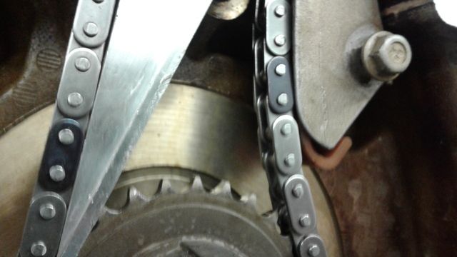
THIS is the only correct path that the Timing Chain should follow:

Yes, I got that. But when you look at the chain sittin on the drivers side guide, it's over on the side of the guide, riding on the edge of the plastic guide clipped onto the metal holder thats bolted to the engine. Instead of the chain being centered on that "rail" it's riding on the edge so that when I start it, it will not follow the guide, but the metal piece the guide is clipped to, where it will eat through the metal guide holder instead of sliding on the actual plastic guide. I have pictures.
The guide isn't in line with the crank sprocket so it doesn't ride the guide correctly and I can't figure out why. If I stick a couple of washers behind the lower bolt hole, it positions the guide so the chain follows it as it should. Without them, it rides the edge. Same with the original guide, and it wasn't like that when I removed it.
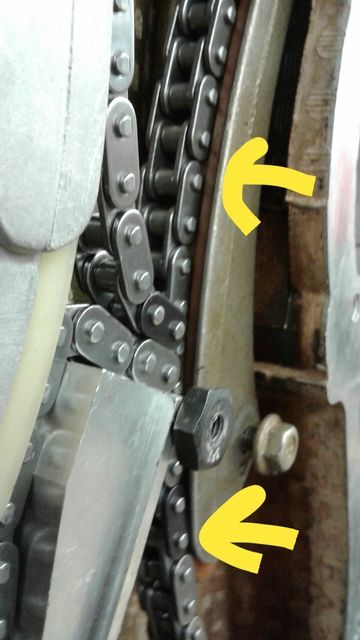
See how the chain is riding the edge of the guide instead of the middle? The crank sprocket isn't in line with the guide on the drivers side. The sprocket sits about 1/8" forward of the guide, causing the chain to want to go over the edge instead of down the middle. Look at the 2nd pic. Follow the chain. See how the upper part of it is in the guide while the lower part of the guide shows the chain riding the edge? That's not supposed to be like that. The original guide shows wear only in the middle of the guide, and none on the edge where the chain is riding on the lower portion. So something is wrong or missing.
At this point, I'm just about to put a spacer or washer behind the drivers side guide lower bolt hole and let it ride. I can't see any other way to kick the lower out that 1/8" or whatever it is. That's why that guide bolt is loose, as well. So I could see how far the guide needed to kick out to have the chain ride in it correctly. Tightening it leaves the guide in a different plane than the crank sprocket. Laying a straight edge against them would show that the crank sprocket is forward of the guide by that tiny bit. So it causes the chain to try to angle back towards the guide, which causes it to ride the edge and not the middle.
Its almost like there's too much endplay in the crank. I know there's not because I checked it, but thats the best description I could find for what's going on. The crank sprocket is too far forward or the guide is too close to the block and needs spaced away from the block. I'm sure it's an issue with the guide and not the crank. I'm just using that as a visual reference to what's going on between the sprocket and guide.
The guide isn't in line with the crank sprocket so it doesn't ride the guide correctly and I can't figure out why. If I stick a couple of washers behind the lower bolt hole, it positions the guide so the chain follows it as it should. Without them, it rides the edge. Same with the original guide, and it wasn't like that when I removed it.


See how the chain is riding the edge of the guide instead of the middle? The crank sprocket isn't in line with the guide on the drivers side. The sprocket sits about 1/8" forward of the guide, causing the chain to want to go over the edge instead of down the middle. Look at the 2nd pic. Follow the chain. See how the upper part of it is in the guide while the lower part of the guide shows the chain riding the edge? That's not supposed to be like that. The original guide shows wear only in the middle of the guide, and none on the edge where the chain is riding on the lower portion. So something is wrong or missing.
At this point, I'm just about to put a spacer or washer behind the drivers side guide lower bolt hole and let it ride. I can't see any other way to kick the lower out that 1/8" or whatever it is. That's why that guide bolt is loose, as well. So I could see how far the guide needed to kick out to have the chain ride in it correctly. Tightening it leaves the guide in a different plane than the crank sprocket. Laying a straight edge against them would show that the crank sprocket is forward of the guide by that tiny bit. So it causes the chain to try to angle back towards the guide, which causes it to ride the edge and not the middle.
Its almost like there's too much endplay in the crank. I know there's not because I checked it, but thats the best description I could find for what's going on. The crank sprocket is too far forward or the guide is too close to the block and needs spaced away from the block. I'm sure it's an issue with the guide and not the crank. I'm just using that as a visual reference to what's going on between the sprocket and guide.
Last edited:
Okay...This is NOT your fault. I can see where this confusion comes from and can very quickly explain the problem: WITH THE FRONT COVER REMOVED... NOW WOULD HAVE BEEN THE TIME TO COMPLETELY REPLACE ALL OF THE OLD, WORN TIMING CHAIN HARDWARE WITH A QUALITY CLOYES SET TO INCLUDE A NEW TIMING CHAIN TENSIONER, NEW TIMING CHAIN, NEW TIMING CHAIN GUIDES AND NEW INTAKE AND CRANKSHAFT SPROCKETS.
Unfortunately... The Still Image showing the Aluminum Wedge Tool Being Inserted on the GM Training Video and shown as the image you posted above was meant for Demonstration Purposes Only to Instruct GM Technicians HOW to Use the Tool and exactly where the Wedge gets inserted between the Timing Chain and the Black Center Bolt in the lower middle area of the Engine Block. But they failed to specify that THE WEDGE TOOL ONLY GETS USED WITH AN OEM TIMING CHAIN ALREADY INSTALLED ON A FULLY ASSEMBLED ENGINE AND WITH THE FRONT TIMING CHAIN COVER IS ALREADY INSTALLED FOR THE PURPOSES OF REPLACING OR SERVICING ONLY THE ALUMINUM ENGINE HEAD.
WHEN THE FRONT TIMING COVER IS REMOVED... THE WEDGE TOOL IS NOT NEEDED. PLEASE REMOVE IT FROM THE FRONT OF THE ENGINE...
It never occurred to me that this confusion would happen without specifying those distinctions that when the Front Timing Cover is Removed...You will have Clear and Open access to ALL of the Timing Chain Components and therefore can clearly observe where to associate a Black Link on the Lower Crankshaft Cog as shown on the Last Diagram I posted. Please follow this “Baker’s Dozen” Set of Instructions EXACTLY as follows:
(1) Fully Compress the Timing Chain Tensioner Plunger and Insert the Temporary Retention Plastic Pin. INSTALL THE UPPER TIMING CHAIN GUIDE… THE TIMING CHAIN RIDES BENEATH.
(2) Guide the Timing Chain over and around the Intake Sprocket with any Black Link aligned to the Timing Mark on the Face of the Intake Camshaft Sprocket.
(3) Slip the Loose Timing Chain down through the narrow Opening in the Head and insert the Intake Camshaft Sprocket onto the Intake Camshaft and hand thread in the New TTY Fastener.
(4) Guide the Driver's Side portion of the Loose Timing Chain down over the Driver's Side Timing Chain Guide and then around the Teeth of the Lower Crankshaft Cog Sprocket...taking care to align a Black Link on the Timing Mark on the lower right hand side of the Small Sprocket.
(5) Guide the Loose Timing Chain around the Small Sprocket and then upwards along the inside of the Passenger Side Timing Chain Guide; with the Guide resting firmly on the outer Foot Pad of the Timing Chain Tensioner.
(6) Lift and Guide the remaining Loose Timing Chain upwards through the Narrow Opening in the Engine Head.
(7) Slip the remaining Loose Timing Chain over the Teeth of the Cam Phaser Sprocket, taking care to align a Black Link over the Timing Mark on the Sprocket.
(8) Install the Cam Phaser GENTLY on the end of the Exhaust Camshaft and be prepared to remove the Camshaft Retention Tool from the two rear camshafts and use a Crescent Wrench on the Hex portion of the Exhaust Camshaft ONLY if the Slot on the end of the Exhaust Camshaft does NOT slip into the inner slot of the Cam Phaser.
(9) REMEMBER… Be Gentle here… you don’t want to damage the Valve Train components… or break the inner metal tang stop built inside of the Cam Phaser to get them to align.
(10) If you had to unfasten the two TTY Fasteners from the Intake and and Exhaust Sprockets after previously tightening them to specifications with the added Torque Angle… you cannot re-use these bolts! Please obtain two New Bolts and then follow their unique tightening, torque and additional Torque Angles required to install the New Fasteners as before.
(11) PULL OUT THE PLASTIC RETENTION PIN FROM THE TIMING CHAIN TENSIONER AND REMOVE THE REAR CAMSHAFT HOLDING TOOL BEFORE TURNING THE ENGINE OVER ENOUGH TIMES TO OBSERVE THE TWO FLATS AT THE REAR ARE ONCE AGAIN HORIZONTAL AND LEVEL AND ALL THREE OF THE BLACK LINKS ARE ALIGNED WITH THEIR RESPECTIVE TIMING MARKS ON THE FACES OF ALL THREE SPROCKETS! If you encounter ANY resistance… STOP and Investigate the Problems immediately. Before you Button Up this engine... It would NOT hurt to coat the Timing Chain and Sprockets and Guides with some Permatex Engine Assembly Lube to "wet down" these otherwise Bone Dry Timing Chain Components and ease their way through the initial harsh Engine Start-Up.
(12) Clean all of the Aluminum Inner Timing Cover Fascia and Grooves of the Old RTV and wipe the surfaces down with a residue-free solvent. Apply a 3MM of AC-Delco Gray RTV to the Inner Cover areas and use caution when installing the cover to avoid damaging the Front Crankshaft Seal, Follow the tightening and Torque pattern to secure the cover as before.
(14) Double check the Work Field in ALL OPEN AREAS of the Engine for Loose Tools and Old Fasteners BEFORE installing the Valve Cover, Harmonic Balancer and All Accessories. Check your Engine Oil Before Starting the Engine and pull the Fuel Pump Relay to prime the top of the engine with fresh oil before re-installing the Fuel Pump Relay and starting the engine at Low Idle. Expect the engine to be NOISY AS HELL for a few minutes while the engine oil warms up and circulates. Do NOT Road Test the vehicle before the Water Temperature is nominal and the Oil Pressure is above 12 PSI at idle.
Last edited:
That makes sense. I did remove the tool and reinsert the plastic retainer thing into the tensioner after the pictures were taken. I also realized at that point I was going backwards and should be putting the head on before trying to button up the timing over and oil pan. Getting easily sidetracked in class, I screwed up and for whatever reason was trying to do the timing cover first when I don't even have the head on the block yet. Thinking about it after I went home, I realized that I was doing things in the wrong order. it didnt occur to me that it could be causing my issue.
Thanks for straightening that out for me. I'm usually not near this scatter-brained. Something about being up here with all these people bird-dogging me while I work, trying to throw in suggestions about things they know nothing about, then constantly asking every time they walk in the shop "you got it about figured out yet" or "'bout how much longer til you got that thang done?"or a number of similar things...just fries my brain man. Half the time, I end up having to walk off and wait until everyone stops congregating at my truck. Trying to watch whose hands go where and then constantly scanning to make sure I haven't left expensive tools, important bolts or parts laying around for someone to move or carry off just eats up my brain power almost. It's beyond aggravating. Anyway. Thanks again for all of the help and advice. Gonna go out here and get to work on this thing.
Edit: so I'm out here. With this drivers side guide bolted and torqued down, there is no way for the chain to follow it correctly. It still ends up on the edge where the raised portion is, instead of between the raised edges of the plastic guide. I even tried the old chain and guides. The crank sprocket still isn't in line with the guide. Not sure how that will go on correctly because the chain is already almost binding trying to make it onto the guide.
Edit #2: Its fixed. I'm almost too embarrassed to say what it was lol. I had the guides bolted in the correct location, but wrong orientation. I bolted the wrong side to the block, putting it upside down and backwards, but still bolted in the correct location. Lol. I'm an idiot. I knew there was a reason that there was a clean spot under the bolt head that was bigger than the bolt head. It was where it was contacting the small bung on the block lol.
Last edited:
When time permits... Would you take a few images of the front of the engine in the areas that you worked on today and post them up so we can see what went on...? And FWIW... Just one more suggestion... As you continue working... If you had images taken of the BEFORE times during your disassembly activities... referring to those images presently for how things should appear when each portion is completed is a good rule of thumb to ensure that what you have undone and then redone... look essentially alike. If anything odd between these comparisons were to become evident...THAT is the time to stop and re-check your work. ;>)
I'll get a few tomorrow. For whatever reason, I was thinking that the recessed areas for the bolt head went against the block. That was why it wasn't in line with the crank sprocket. I had the recesses against the block, effectively moving the guide towards the block 1/8". And putting it out of line with the chain.
No Problem... Perhaps your Training Mates apparently don't understand the difference between "Involvement" and "Commitment"... It is best described as a "Bacon, Lettuce and Tomato Sandwich"... in which the Lettuce and Tomato are "Involved"... But the Pig... is "Committed"... LOL.
It takes such dedication to work as long and hard as you have on this Engine to understand the differences involved here as well... You Get It... But perhaps... they never will. Keep Your Eyes Open to problems like these, Brother...and Keep On Trying. Soon enough...it will all come together. and when you victoriously drive that SUV out of there... they can all stand around and watch you go.
It takes such dedication to work as long and hard as you have on this Engine to understand the differences involved here as well... You Get It... But perhaps... they never will. Keep Your Eyes Open to problems like these, Brother...and Keep On Trying. Soon enough...it will all come together. and when you victoriously drive that SUV out of there... they can all stand around and watch you go.
LMAO! That'd be lovely. This stuff is my passion. I love cars, engines, anything that makes power really. But working on cars is really what I love. That's why I finally chose it as a career. That, and I was light years ahead of everybody that was in my automotive tech class in '09. But I didnt take it for the same reasons they did. They needed to learn. I just needed something saying I had formal training so someone would hire me while having no professional experience at the time. A year into class I was working at a small-town GM dealership as a line tech. There was only 4 of us, so we didn't have dedicated power train guys, or a drivability guy, etc like most big dealerships have now. We did whatever we were assigned. From simple warranty work to full engine teardowns, timing chains on the Acadia's, etc....
Anyway. You're definitely right. Commitment is it. I don't think I could love it anymore than I do already. I spend every waking moment doing something with cars. Whether I'm reading forums, fixing something, or whatever. 95% of my life is dedicated to this sh*t. I wouldn't have it any other way.
Spent most of the morning yesterday getting the deck surface prepped for reinstallation of the head. Getting all of the rubber off that was left by the channels on the headgasket and cleaning up the tops of the pistons mainly. Went through quite a bit if reading material to determine the best way to clean it. Seems that brake cleaner and lint-free towels work great. Better than scraping with a blade, even with the blade at 90* angle to the deck surface. I still managed to barely mark it up in a couple of spots until I switched to brake cleaner and a towel. It takes a little elbow grease, but there's no possibility of scratching it up any more so I stuck with that after determining that I didn't want to use scotchbrite due to possible aluminum particles embedded in the scotchbrite during manufacture. I didn't use a 3M disc(pictured below) because they're ceramic and didn't need that in my engine, either. As well, I tested it on a non-sealing surface and it left all sorts of marks in the aluminum so that was out, too. All suggestions were to use either of those 2 methods, the razor blade method, and/or brake cleaner/chemical wipedown afterwards. So I went with the least destructive.
3M disc I bought is just like this one below. Green is 50 grit, yellow is 80 grit and white is 120.

And with the ninja edit: the cam sprocket bolts are TTY, too!?! Damnit. I was just at the dealership picking up RTV and a new washer for the harmonic balancer yesterday lol. Pn 12578073 pictured below. Couldn't find it at any parts store.
Edit #2: One other thing. The tops of the cylinder bores don't look that good. Since you have yours apart and no pistons in it, MRRSM, can you measure how far down the piston the first ring land is from the crown, please? I'm sure that this area of the cylinder bore in question is above the highest point that the top ring reaches. I just want to be sure, though. Thanks in advance.
Anyway. You're definitely right. Commitment is it. I don't think I could love it anymore than I do already. I spend every waking moment doing something with cars. Whether I'm reading forums, fixing something, or whatever. 95% of my life is dedicated to this sh*t. I wouldn't have it any other way.
Spent most of the morning yesterday getting the deck surface prepped for reinstallation of the head. Getting all of the rubber off that was left by the channels on the headgasket and cleaning up the tops of the pistons mainly. Went through quite a bit if reading material to determine the best way to clean it. Seems that brake cleaner and lint-free towels work great. Better than scraping with a blade, even with the blade at 90* angle to the deck surface. I still managed to barely mark it up in a couple of spots until I switched to brake cleaner and a towel. It takes a little elbow grease, but there's no possibility of scratching it up any more so I stuck with that after determining that I didn't want to use scotchbrite due to possible aluminum particles embedded in the scotchbrite during manufacture. I didn't use a 3M disc(pictured below) because they're ceramic and didn't need that in my engine, either. As well, I tested it on a non-sealing surface and it left all sorts of marks in the aluminum so that was out, too. All suggestions were to use either of those 2 methods, the razor blade method, and/or brake cleaner/chemical wipedown afterwards. So I went with the least destructive.
3M disc I bought is just like this one below. Green is 50 grit, yellow is 80 grit and white is 120.
And with the ninja edit: the cam sprocket bolts are TTY, too!?! Damnit. I was just at the dealership picking up RTV and a new washer for the harmonic balancer yesterday lol. Pn 12578073 pictured below. Couldn't find it at any parts store.
Edit #2: One other thing. The tops of the cylinder bores don't look that good. Since you have yours apart and no pistons in it, MRRSM, can you measure how far down the piston the first ring land is from the crown, please? I'm sure that this area of the cylinder bore in question is above the highest point that the top ring reaches. I just want to be sure, though. Thanks in advance.
Last edited:
I'm glad we are on the same frequency with the matter of your mechanical acumen and the future it will hold in store for you. When you're Smart... People Need You... ;>)
As for cleaning the surfaces of anything made of Aluminum... I agree that it is wise to steer clear of using those Ceramic varied grit abrasive pads... as they will most certainly cause dimples and wavy depressions on the Block Surfaces and can eat away enough metal rapidly causing enough subtle damage to guarantee that the MLS Gasket will not seal correctly. I'd like to suggest that instead you might try using Ordinary Aluminum Foil... all crumpled up into a Ball... just like a Brillo Pad and apply some 3 & 1 Oil to the block surfaces while using the Aluminum Foil Pad.. .GENTLY ... to remove the residual MLS Gasket Adhesive and carbon residues.
Don't use extreme pressure and frequently make new pads to keep their surfaces from breaking down and dropping tiny pieces of Aluminum Foil all over the place. Wipe up the surfaces as you go and keep the Oil fresh on the areas being treated. The Block will need a thorough wipe down with Lacquer Thinner or Acetone before laying on a fresh MLS Gasket and the Re-manned Head.
If you are removing the Pistons... The fastest and least abrasive way to clean your Pistons is to purchase the Gallon Can of Berryman's Carburettor Cleaner and submerge the Pistons after removing all the Old Rings... It will rapidly soften and dissolve the built up Carbon Residues. If not and the Pistons are In-Dwelling... Just get a couple of cans of Foaming AC-Delco Top Engine Cleaner and fill the all of the Cylinders and Piston Tops to the Brim with that stuff. The Carbon Residues will dissolve completely with no need for any Abrasives of Elbow Grease.
Cover over the areas of the Engine Block with plenty of sealing Saran Wrap and some heavy, clean Beach Towels to absorb the smell or everyone in the shop will hate you... and when you are ready the next day... Use a few rolls of Lint Free Shop Paper Towels sold at Autozone to sponge out the cylinders and wipe off the Pistons... making sure to drop those TEC soaked Rags right into a Garbage Bag and tie off the ends to keep the vapors down to the minimum. Avoid breathing the fumes from this stuff as much as possible... the solvent is capable of dissolving Brain Lipids and Tissues in concentration so please be careful when using this stuff.
The Piston Measurements from the Piston Crown to the Top Compression Ring Land measure out at 3 MM and the Second Compression Ring measures down from the Piston Crown to a depth of 8 MM at the upper Land... and these measurements only apply to the later 2003-2005 Pistons that have the 1.2 MM Thick Top Ring, 1.5 MM Middle Thick Compression Ring and 1.2 MM Thick Oiling Rings.
Last edited:
I've never heard of aluminum foil. I'll have to give it a shot before I drop the head in place tomorrow. I started to today and then pulled the head back off to go through all of the head bolt holes once more and make sure they were clean. Almost all of them had coolant in the bottom and I cant seem to be able to get it all out. I've blown them out multiple times with shop air but there's still coolant in the bottoms. It's only a tiny bit from what I can tell. My borescope won't fit more than an inch into the bolt hole so I couldn't look inside that well. I did notice that almost all of them reflected light back like a mirror when shining a pen light into the holes.
I sat the head on 2 phone books(1 on each end of the head) with the combustion chambers unblocked so I could rotate the cams into position to install the camshaft holding tool. I figured I would loosen and re-tighten all of the camshaft bearing caps to make sure they were at the correct torque. I tried to loosen the first cap on the passenger side and it wouldn't budge using quite a bit more force than 106 in.lbs with a 1/4" ratchet. So I grabbed the inch.lb Snap-On torque wrench, set it to 106 in.lbs and attempted to loosen the bolt/check and see if the wrench clicked when I started loosening. It clicked and the bolt didn't move. Checked the other bolt in that cap and the next 5 caps. Three on the drivers side and two more on the passenger side. They were all tightened well beyond the specified value. I figured there would be a diagram of which order to tighten the bolts, similar to a crankshaft, but couldn't find anything online or in AllData, which uses the GM factory service procedures. Only to make sure the caps were in their correct locations, which were known by the location marked on each cap, and then tighten to specified torque. Is that correct? There is no tightening procedure? Is there anything I should check before I put this together after finding this? Should I check bearing clearances and camshaft endplay to make sure the bearings weren't crushed/compacted or something, leaving more clearance between the cam and bearing shells? I have plastigage, inside bore micrometers, snap gauges, all kinds of stuff. I never imagined they would just tighten bolts haphazardly, with no regard for anything else.
Thanks for the measurement. I'm sure that's what I'm seeing. The space above where the top rings stops at TDC, from the ring to the top of the cylinder bore. I'm not removing the pistons from the block. I was just going to attempt to clean off as much as possible while each piston was at TDC. There are a couple of spots in a couple of cylinders that's questionable. Like coolant was on the cylinder wall of cylinders 1 and 6 while they were at TDC and the engine still in the truck. Since I never rotated the engine, I had no idea it was there. It's not visible brown rust or anything. It's a random, oval-shaped outline basically. Like someone outlined a random blob of water with a pencil is the best way I can describe it. You cant feel it. It doesn't catch your fingernail or cause the surface of the cylinder bore to feel any different in that area, as far as I can tell. It didn't wipe off, though, so I figured it wasn't something to dismiss. Not sure what to do. Run it?
Last edited:
Anyone got any suggestions on how to get the cam sprockets on? Finally got it right so all the links match their marked spots. At first, I was a half link short from the exhaust sprocket to the crank sprocket. It wouldn't reach until I adjusted the camshafts to spec(a .005 feeler gauge won't fit under the straightedge). I have it all lined up but the 2nd sprocket won't go on. It needs another .010 movement to go over the end of the cam. I can get the peg lined up and into the hole on the cam, but it won't go on the cam completely. So? What do I do? I doubt I can force it on with the cam bolt by tightening it, drawing the sprocket down onto the cam. Anybody? I searched and didn't really find a solid answer. Could I remove one or both guides to gain enough slack in the chain to get it on, then slide the guides into place and bolt them down?
2nd. Is the cam phaser in the full advanced position when Delco(Delphi?) is parallel with the head? Or do I need to rotate the cam phaser?
Went and got a blower with an extension on the end that reached down to the bottom of the bolt holes and blew them out vigorously. So that's all done. Ordered some ARP assembly lube, picked up some engine assembly lube for the cam and pulled the bearing caps. I didn't realize there were no bearings and it uses the cap itself as the bearing material. A few were scored quite a bit. The cam itself looked good, with no scoring or noticeable wear. So I tightened them all to spec and went with it. There's really not an order to tighten them? That seems wrong to me but I'll go with it if it's correct. Anyway. That's all I got for now. Sorry for not getting more pics of the guides and stuff after my screw up. I forgot about it completely. Been so busy with class, and home and my new puppy, and getting this engine done that it slipped my mind.
Thanks.
Last edited:
Okay… Lets take these subjects on in an organized manner.
But First… A Few Small Suggestions:
Please… Take Pity on your Readers… and for every 1.5” to 2” of Dialogue… Introduce a Paragraph Break. Otherwise… everything gushing out of your clever mind when seeking to understand and obtain discrete facts just blends together into a “Wall of Words”. Without a Pregnant Pause here and there… it becomes impossible to break things up into Bite-Sized and Mentally Digestible Bits. Please don’t misunderstand this request as one for wanting LESS to read. On the contrary… The Richer and More Vivid your Documentation is… The Better we can Understand what you are describing and seeking to know.
If you Write Out what you want to communicate in LibreOffice Writer Word Processor First… then you’ll get a better opportunity to think about, re-arrange and consolidate your topic ideas and throw in the occasional Spell Check when needed. You’d be surprised how much easier it is to do the Thinking Grunt Work first in the WP and then when you sign on… Just Copy and Drop your finely polished dialogue onto the New Post Screen at GMT Nation. Besides that… when you save your own Dialogues… in time.. someone else will come to GMT Nation asking similar questions that you can assist them with using what you have already written. ;>)
This Link will show you all of the Specs and Acceptable Range of Tolerances for the GM 4.2L LL8 Engine:
http://gmtnation.com/forums/threads/the-gm-vortec-ll8-links-and-specs-library.16738/
Here is a video of some Students in Training during the Re-Assembly of the LL8 Aluminum Engine Head during a Bench Build. These Fellows are echoing what their Instructor told them to do in order to Install One Camshaft after inserting the Valve Lash Adjusters and placing the Camshaft Caps in Place. The VOP (Video Original Poster) will explain to the other student how to tighten down the Caps in a manner that gradually draws down the Camshaft over its full length and neither over stress nor bend it or Goof Up the Base of the Camshaft Journals in the Engine Head:
Aligning the Cam Phaser Sprocket to the Exhaust Camshaft:
When you get the to the point where you are ready to install the Exhaust Cam Phaser Sprocket on to the Vertical Slot in the Front Nose of the Exhaust Camshaft… it will be necessary to:
(1) Ensure that the Timing Chain Tensioner is COMPLETELY COMPRESSED AND PIN-LOCKED.
(2) Ensure that the CAMSHAFT HOLDING TOOL IS COMPLETELY REMOVED.
(3) Ensure that the BLACK LINK IS ALIGNED ON THE CAM PHASER SPROCKET.
(4) Ensure that the CRESCENT WRENCH IS ADJUSTED ON THE EXHAUST CAM HEX SPOT.
(5) Ensure to ROTATE THE CAMSHAFT VERY SLIGHTLY TO ALIGN THE CAM PHASER SLOT.
(6) Ensure that you DO NOT EXCEED 25 DEGREES OF MOTION OR THE CAM PHASER WILL BE DAMAGED. BE VERY, VERY GENTLE HERE....
(7) Ensure that THE BRAND NEW TTY LONG BOLT IS HAND THREADED IN BEFORE RELEASING THE VERY SLIGHT PRESSURE ON THE CRESCENT WRENCH.
Once these procedures are complete... The Two Black Links should be aligned over the Timing Marks on BOTH Sprocket... The Black Link on the Crankshaft Sprocket should likewise aligned on the Timing Dot on the Crank Cog... and the word DELPHI should be straight and level with the upper edge of the Aluminum Engine Head.
All that remains to be done is to REMOVE THE CAMSHAFT HOLDING TOOL... REMOVE THE TIMING CHAIN TENSIONER PIN... AND VERY SLOWLY AND CAREFULLY ROTATE THE ENGINE CLOCKWISE... FOR AS MANY AS 14 ROTATIONS ...UNTIL THE EXACT SAME ALIGNMENT APPEARS AS MENTIONED ABOVE.
If at any time you feel even the slightest solid resistance... other than the gradual compression and expulsion of air entering and exhaling from the six cylinders... STOP and Investigate the Problem. If all goes well and these events proceed as described... Police up the Top of the Engine Head for any loose tools, parts, dirt or anything not made to be there. Then, after coating the Valve Train Lobes... the two Sprockets, the Timing Chain and Guides with Perma-Tex Engine Assembly Lube... proceed with installing the Gerotor Oil Pump into the Oil Pick Up Tube.
Finally... align-install and bolt on the Front Timing Chain Cover... using care when slipping the Front Crankshaft Seal over the nose of the Crank. Remember to install and Torque Down the Fastener holding the Oil Pick Up Tube to the underside base of the Gerotor Pump from underneath the vehicle prior to installing the Crankcase-Oil Pan.
Last edited:
Thanks. Sorry about the walls. I don't usually do that. I'll be more aware of what and how I'm writing in the future. I appreciate the suggestions.
That's what I was looking for in regards to bolting down the bearing caps. I'll go through and make sure they're done once more just to be sure that they're done to my satisfaction. It only takes a few minutes. Did I see these correctly in that they don't have actual removable bearings for the cams? What is one supposed to do with excessive wear? Replace the head??
Regarding installation of the sprockets, I'm pretty sure I did the installation correctly, which is why I don't get that the last sprocket, whether it's intake or exhaust, acts like it stills needs another 10 or 20 thousandths movement to get the entire hole of the sprocket onto the nose of the cam. The peg will go into the vertical slot, but there's just not enough movement to get the entire sprocket on. It's literally that close. If there was .010 more play in the chain, it would probably go on. But it won't. Is it supposed to be that difficult or am I supposed to be able to just slide it on?
In the case where the All Aluminum Camshaft Bearing Surfaces are Badly Worn... The Machine Shop would simply... very slightly ... shave down the upper support bosses of the Cam Shaft Bearing Caps and then Align Bore or Fine Hone a Brand New Hole --> .... Dead Center from Front to Back... moving the Exhaust Camshaft Base Circle slightly closer to the Engine Head AND likewise, moving the Cam Phaser closer to the Engine Head as well... but leaving a refreshed and smooth Bearing Surface for the Camshaft... Straight as a Rifle Shot.
As for getting the Cam Phaser Sprocket installation Done... Lets try this:
Completely Remove the Timing Chain and hand rotate the chain to move to a Different Set of Three Black Links for alignment on all Three Sprockets and install the Timing Chain after flipping the chain "front" to the "back" side in relation to the orientation it is in right now. I know it sounds like a Chinese Fire Drill (Which by the way.... is NOT confusing to the Chinese...) But think about it .... moving to the Sprocket Timing Marks to the Alternative Black Links and Flipping the Chain Face may just allow for those Tiny, Obstructive Variances... to Disappear.
But... If that Does Not Do the Trick:
Completely Remove the Chain and examine the Outer Edges of the Inner Curved areas of the Cam Phaser Sprocket for indications that it may have been Re-Built from an Original Worn Unit. Feel very carefully along BOTH sides of the outer edges of where the Chain Rollers have made deep contact into the Sprocket for any Very Sharp Edges created by prior pressure expansion wear forcing the metal outwards. Trust me... If the "New Unit" is a Re-Manned Old Cam Phaser ... You'll definitely find it out if you can feel ANY sharp edges in those areas.
These sharp edges can Catch on the Inner Link Plate areas of the Brand New Chain and prevent the Rollers from completely seating all the way around and into the Sprocket. If you discover these Sharp Artifacts ... Remove the Cam Phaser to the Bench and with the entire Unit taped up inside a Plastic Bag to prevent contamination with Metal Particles... Run a Small Flat File or a Fine Stone Dremel Wheel around the Outer Perimeter where the sharp metal extrusions are and carefully file them down. Super Clean the Cam Phaser and Run a Neodymium Magnet all over it before attempting to re-install the unit.
Last edited:
That's what I figured with the cam bearings. Thanks for the confirmation. I never imagined it wouldn't have actual bearing shells, like the crank and rods do.
I think that's all for now, until I get back on Monday.
Oh, and I perforated my eardrum yesterday. Ugh.
I think that's all for now, until I get back on Monday.
Oh, and I perforated my eardrum yesterday. Ugh.
Sorry about the Eardrum... Oddly enough... They can self-repair and regrow back pretty quick ...as long as you don't Laugh, Yawn and Sneeze or Cough with a Mouthful of Oreo Cookies and Milk all at the same time... you should be Okay. I had a Doctor treating me once for a Bad Earache say, "Bobby... The only thing you should EVER be putting inside of your Ear to Clean it... is your Elbow..!" ;>)
As for the "All Aluminum Bearings" in the GM 4.2L LL8 Engine Head... The fact is that for every Two Rotations of the Crankshaft... The Camshaft(s) only turn Once. Couple this idea with the number of valves (24) having a Lower Mass Per Valve/Cam Lobe and an increased collective surface area that reduces individual lifter lobe pressures... the stresses on the Intake and Exhaust Camshafts in the Atlas LL8 Engine are much lower than for a Standard Single Camshaft moving HUGE Intake and Exhaust Valves the size of Tea Cup Saucers up and down.
Ergo... with such a short distance for the Valve Lash Adjusters (VLAs) to move up and down while actuating full Roller Bearing Rocker Arms under Very High Oil Pressure (65 PSI) being readily available via the Large Lubrication Grooves Machined into the Camshaft(s) Bearing Base surfaces in the Head... It all translates from having much lower rotational velocities in the presence excellent lubrication into having Very Low Friction acting upon the Valve Train.
And so... the GM Engineers Saved the Costs in the Design, the Parts and the Maintenance that are required for the other components using "clamshell bearings" to work well together further down inside of the Engine. Please observe the Rotational Ratio of Crankshaft to Camshafts in the attached GIF as a demonstration of how they managed to pull this off ...without using the familiar "Babbitt" Bearings:
Last edited:

Well, I got the sprockets on. 14 revolutions later and the timing marks are still lined up. Wonderful. I appreciate the detailed explanation. Thanks.
One question. In the timing cover kit, TCS 45052, what is the skinny o-ring for? I used the fat one in the timing cover and the flat one on the oil pump pickup tube. That leaves the skinny o-ring. Any ideas?
One question. In the timing cover kit, TCS 45052, what is the skinny o-ring for? I used the fat one in the timing cover and the flat one on the oil pump pickup tube. That leaves the skinny o-ring. Any ideas?
Is it tiny? It could be for the small timing cover screw but I don't think I used one on it. If you have a picture with a coin as a reference size next to it.
The Felpro TCS 45052 Kit probably comes with an extra "O"Ring that ordinarily fits over the end of the Original Style Oil Pick Up Tube to replace the Old, Flattened and Worn Out one that seals itself inside of the groove in the base of the Front Cover Gerotor Oil Pump.
If you have the Newer Flavor of the Updated Oil Pump... you will NOT need to install it as the new version has the longer insert pick up tube end and no hollowed out upper flange manifold to accommodate the Round "O" Ring in the base of the New Gerotor Oil Pump. The Newer Version has an Orange, Rubber Impregnated Vacuum Sealing Grommet Washer instead. Please don't "Mix the Metaphors" between these two sealing methods. ;>)
Does it resemble the smaller item in this image?
Yes, it is exactly like the lower o-ring in your pic. It would be the lower right o-ring in the pic I posted, also. Thanks. I figured that's what it was but wanted to be sure. I used the flat,metal washer looking seal with the silicon seal impregnated in it on the pickup tube. The original was metal/orange and the new one is metal/blue as pictured below.

Been out of class the last 2 weeks and will be out next week, too, so it will be a bit before I get back to it. I need to bolt down the head, install the timing cover and oil pan, and then hopefully get it back into the engine bay.
Been out of class the last 2 weeks and will be out next week, too, so it will be a bit before I get back to it. I need to bolt down the head, install the timing cover and oil pan, and then hopefully get it back into the engine bay.
After you button up the Front Timing Chain Cover and install the Crankcase-Oilpan... Your next critical component installation will be the proper fastening, tightening, torquing and application of the correct TTY Angle of the Harmonic Balancer. Unlike the more familiar design of "The Woodruff Key" hardened insert that fits into a machined groove in the nose of the Crankshaft... GM opted to go cheap and simply drill out a hole and plug it with a pin that more... and sometimes less... is supposed to keep the slide on Crankshaft Cog in a proper relationship with the Reluctor Ring situated further back on the Crank at the 5th Main Journal.
If the pin gets worn or bent... or the inside Square Groove of the Crank Timing Cog is damaged... it will be impossible to solve any P0014 and/or P1345 error codes as a result. Hopefully, you have installed a New Crankshaft Timing Cog Sprocket as precautionary measure... but if not and you can recall the pin in the Crank as being in good shape... this will prove non-problematic.
But now the real thing to look out for comes into play... The Harmonic Balancer has No Woodruff Key Slot and relies entirely upon the force of the initial Torque Setting of 110 Ft Lbs... plus an additional 180 Degrees of Torque Angle in order to have enough friction to really hold it well against the tendency it will have to work itself loose. The easiest way to accomplish the final tightening of the Torque Angle is after the application of 110 Ft Lbs of force... take a White Oil Paint Marking Pen and draw a vertical line across the face of the Crankshaft Bolt that extends above and below onto the Timing Chain Cover. Then as you tighten down your Brand New Crankshaft Bolt... you won!t require a fancy Torque Angle Meter to ensure that when done... the line will have been rotated a full 180 Degrees.. and literally "lines up". If the Harmonic Balancer is not so fastidiously attached with that new special washer you bought to fit on the inside of th HB... and it loosens in time... besides getting unusual CKP error codes and experiencing random stumbling Engine performance... the motor will eventually try to shake itself apart.
You cannot and should not use any kind of puller or Harmonic Balancer restraining tool as these methods will NOT work to keep the Crankshaft from rotating while installing the HB Crankshaft Bolt. Rather... use two pairs of Vice Grips to grab the outer hobbed-out Ring Gear of the Flex-Plate adjacent two Engine Stand Support Bolts and lock and block the plate securely from being able to rotate in a Clockwise direction. Be careful to protect the Ring Gear from damage by using some thin flat pieces of either Aluminum or Copper to prevent the teeth of the Vice Grips from digging into and damaging the edges of the Flame Hardened Steel Ring.
Last edited:
- Status
- Not open for further replies.