fireman4215
Member
- Joined
- Dec 18, 2011
- Posts
- 813
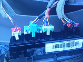
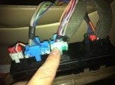
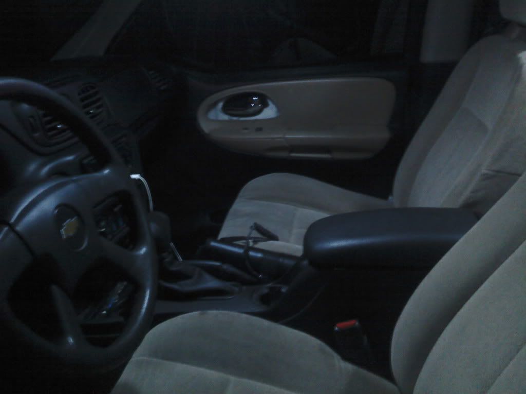
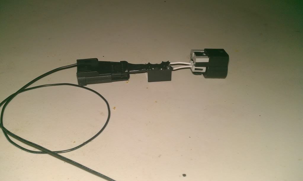
I started by locating the wires in the door that controlled the side marker. Green and white wires
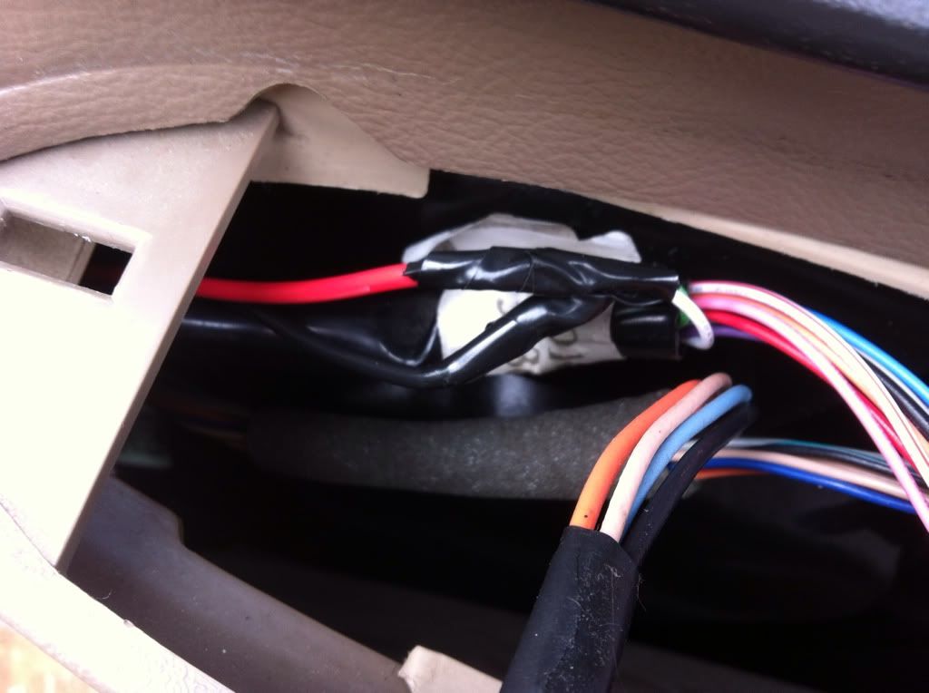
Then I ran them through the door and into the cabin. (no pics of my pathway)
I had to drill a small hole in my floor but i got a rubber gromit to put in it.
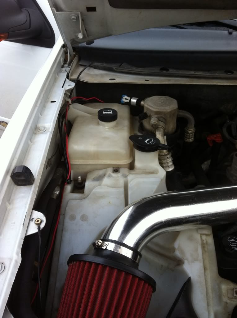
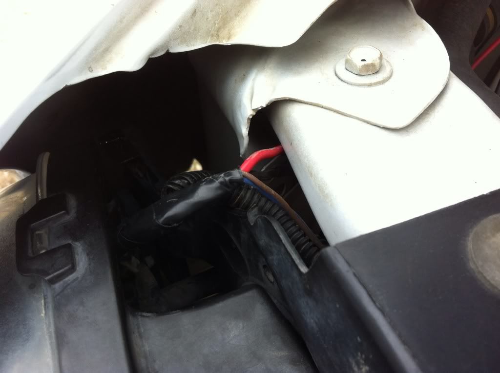
I ran the wire around the side of the engine bay.
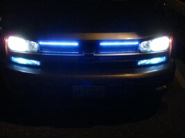
Then tied into the front side marker.
If ya have any more questions just ask Ill help anyway I can.
Then I ran them through the door and into the cabin. (no pics of my pathway)
I had to drill a small hole in my floor but i got a rubber gromit to put in it.
I ran the wire around the side of the engine bay.
Then tied into the front side marker.
If ya have any more questions just ask Ill help anyway I can.


 If you need more info to help me, just let me know!


 Hope you have better luck.
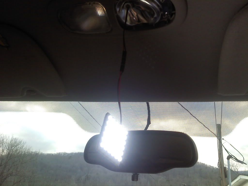
 That thing is freaking HUGE!!! I hope you're able to find one that's a lil more reasonable in size for this application.
  Luckily the liquid tape tears and peels off without too much hassle and doesn't damage anything beneath it.