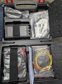
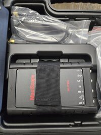
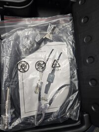
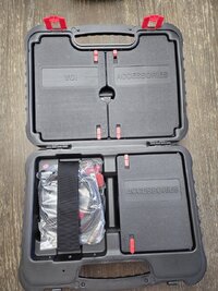
How To Use PICO #2204A & HANTEK #1008C Oscilloscopes

mrrsm

Original poster
Lifetime VIP Donor
Supporting Donor
Member
Oct 22, 2015
8,267
Tampa Bay Area
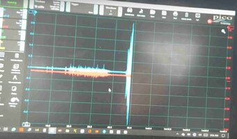
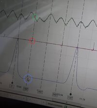
Can you Diagnose a Crank-No Start on a 1999 GM or GMC V-8 Truck using a Pin Point Probe Test Light and a DMM? Sure. Maybe ... OR... You could watch what THIS Dude from "The Final Stop Auto Tech" YouTube Channel is up to with what he does with the Oscilloscope Feature of his Autel Diagnostic Tablet to make THIS Ground-2-Ground Diagnosis and Repair with his "O" Scope a SHORT & SWEET One:


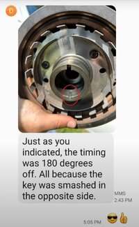
Here is the same Dude working on a problem with 'Fresh Engine Swap of a 6L Engine" into a 2006 Trailblazer using THREE Signal Inputs into his "O" Scope to Dope Out a SERIOUS Timing Issue:


And HERE is a Supporting Video from Advanced Level Auto using a SIMILAR Approach to achieve a SIMILAR Diagnostic Result on a SIMILAR Vehicle:


And a "Shade Tree Kid Mechanic" with GOOD Diagnostic Instincts who SORTS IT OUT:

 
Last edited:

mrrsm

Original poster
Lifetime VIP Donor
Supporting Donor
Member
Oct 22, 2015
8,267
Tampa Bay Area
And Now for some Very Inexpensive and Very Cool Oscilloscope Accessories from ROTKEE that are Damned Near MUST HAVES for things like Pressure Pulse Sensing Diagnostics!!!

Guys... THIS is the Kind of STUFF that is normally WAY TOO EXPENSIVE to Find and Buy... So Visit the ROTKEE Link mentioned in this Video if you want to expand upon your "O"Scope Diagnostic Possibilities ...without Going Broke:


NOTE:
In order to make it E-Z-R for anyone interested in purchasing any of the "O "Scope Sensors mentioned in the above Video, I prepared "My ROTKEE Wish List" linked below as a PDF that shows the Images of all these Items by their Names and Prices and (because the Site is Multi-Lingual) by clicking on ANY or ALL of what you might want to buy...they are Hyper-Linked in English back to the Main ROTKEE Home Page.

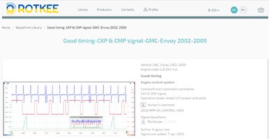
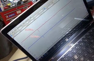
Also... Drop in at the On-Line ROTKEE Wave Form Library then View & Download a mixture of Known Good and Known Bad Wave Forms... For Knowledge, For Practice and For Comparison against whatever YOUR Troubled Investigatory Wave Forms happen to look like:

GMLL8KNOWNGOODCAMCRANKCORR.jpg

This Place has Great Value to any Automotive Diagnostician using ANY Make or Model of Oscilloscope... Start with observing THESE (92) Chevrolet Wave Forms... Download Them ...and... USE THEM:


Then... REALLY Check Out ALL of The YouTube Videos within this Search String: "Automotive Oscilloscope"... Every Single Chance You GET!


I should have covered this Topic a long time ago, but since. "There Is No Time Like The Present..." Here Goes:

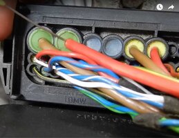
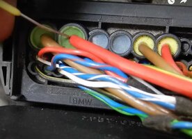
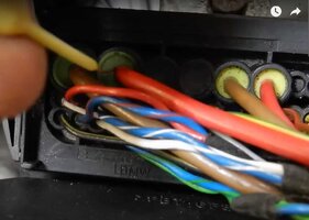
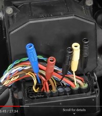
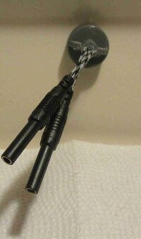
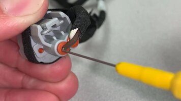
Whenever using the Needle Probes with the 4mm Female Banana Pin Lead attachments, follow the Technique being used by "Diagnose Dan" in THESE Images to avoid damaging the Circuit Wire, The Circuit Wire Insulation OR the Soft, "Gummy" Weatherpack Silicone Seals:

DIAGNOSEDAN1.jpgDIAGNOSEDAN2.jpgDIAGNOSEDAN4.jpgDIAGNOSEDAN5.jpgDIAGNOSEDAN6.jpgDIAGNOSEDAN7.jpgDIAGNOSEDAN8.jpg
 

Attachments

  • ROTKEEWISHLIST.pdf
    44.2 KB · Views: 1
  • DIAGNOSEDAN3.jpg
    DIAGNOSEDAN3.jpg
    83.7 KB · Views: 2
Last edited:

mrrsm

Original poster
Lifetime VIP Donor
Supporting Donor
Member
Oct 22, 2015
8,267
Tampa Bay Area
Can you use an Oscilloscope to "Verify a Bogus Name Brand Spark Plug"...?

Oh Yeah...


mrrsm

Original poster
Lifetime VIP Donor
Supporting Donor
Member
Oct 22, 2015
8,267
Tampa Bay Area
Let's take a moment to *Down-Shift Gears* and take a look at some of the LEAST Expensive Oscilloscopes worth knowing about for The Curious, The Novice and The "O" Scope Newbeez who might want to experiment with one of the Single Channel, Modestly Featured Oscilloscopes that are also Very Reasonably Priced as an Introductory Familiarization Device:

No Offense Intended here...But I DO Need To Warn You... Once you Get Your Feet Wet with making Simple Wave Form Diagnostics:

"THERE'S NO GOING BACK... TO THE RISK OF BECOMING ... A PARTS-CHANGING-HACK"


Disclaimer:

I Do NOT Own or Use any of these Single or Dual Channel Hand-Held Oscilloscopes and I Do NOT Sponsor either the eBay Sellers or the Manufacturers of these Inexpensive Oscilloscopes.

CAVEAT EMPTOR... Buyer Beware:

While purchasing simple "O" scope Systems like these, The New Users should know that while they are NOT designated for use with Automotive Diagnostics... they WILL sense the Wave Forms being investigated during Automotive Diagnoses when they are Set Up Correctly.

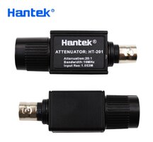
Thus it follows on that if New Owners-Users desire to measure High Voltage Modules and Components such as Coil Over Plugs (COP) Coils and EFIs or Solenoids, care must be taken to always install a Hantek 20:1 High Voltage BNC Connector Attenuators in line with any Leads and Probes in order to protect the Oscilloscope from High Voltage DAMAGE. The Hantek 20:1 BNC Connector Attenuators are available on Amazon for around $10.00 to $12.00 + S&H.
 

mrrsm

Original poster
Lifetime VIP Donor
Supporting Donor
Member
Oct 22, 2015
8,267
Tampa Bay Area
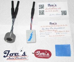
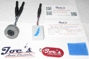
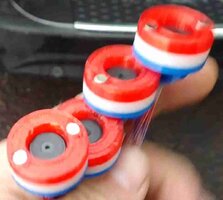
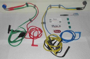
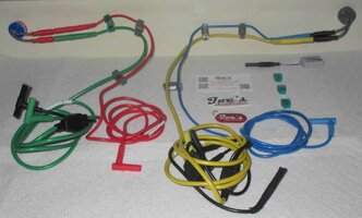
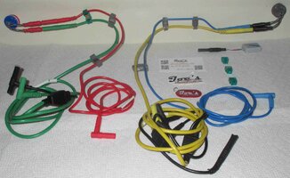
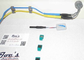
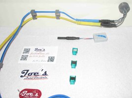
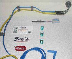
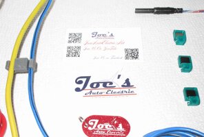
I never stop looking for ROTVs (Relevant Oscilloscope Training Videos) but sometimes ...it surprises even ME for what is available to watch on YouTube. The latest stuff concerns dropping in on Joe's Auto Electric YT Channel and ending getting Two Very COOL "O" Scope Sensors that should *Spark* Up some interest if you are just now getting into either Basic Oscilloscope Diagnostics or trying to do some more esoteric Sound and Vibration Diagnostics of seemingly intractable Noisy Suspension Issues.

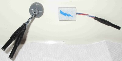
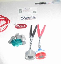
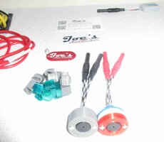
I'll let HIM describe how they are applied and I'll show you the two that I just got that are SO FRIGGIN' KOOL...and for not too much Moolah, either...(Visit the JAE Store below) :


(1) Magnetic Vibration Sensor (Use in 1-4 Units for "O" Scope Isolation of Suspension Issues)

(2) Rectangular Secondary Ignition Wave Form Sensor (Use with Clear Double Sided Tape)


JOESAUTOELECTRICSENSORS1.jpgJOESAUTOELECTRICSENSORS2.jpg
JOESAUTOELECTRICSENSORS3.jpgJOESAUTOELECTRICSENSORS4.jpg

And here are Three "Diagnostician "O" Scope Karts" being Unveiled BY Three Serious Power Users:


Last edited:

mrrsm

Original poster
Lifetime VIP Donor
Supporting Donor
Member
Oct 22, 2015
8,267
Tampa Bay Area
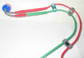
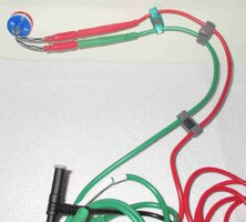
It is possible to perform Non-Invasive, Sub-System Suspension Noise Diagnostics in the following manner:

Tools:

Windows Laptop Computer using Windows OS
Inexpensive PICO-Scope Two Channel Model # 2204A Oscilloscope
FREE PICO-Scope Automotive Diagnostics Software (Version 6 is preferable)
Download for FREE via www.picoscope.com
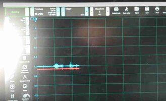
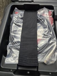
Joe's Auto Electric Magnetic Noise Pick-Up Sensors
Joe's Auto Electric Magnetic Lead Supports-Line Holders

Methods:

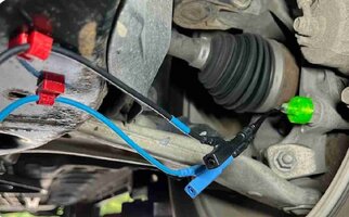
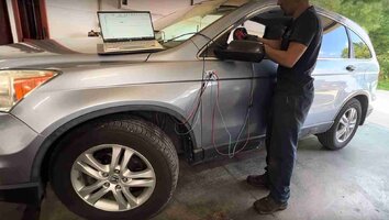
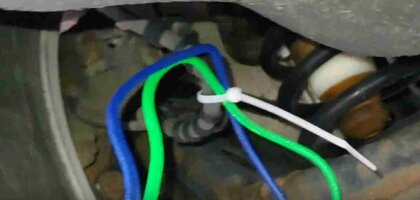
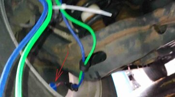
Attach the Magnetic Pick-Ups to the opposing Wheels or Suspension Sub-Components
Attach and isolate the Sensor Leads via the Magnetic Holders back to the PICO Equipment inside the Cab of the Vehicle all set up and resting upon the Passenger Seat.
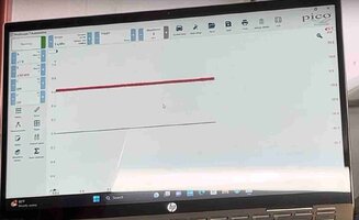
Run the PICO-Scope Automotive SW and Set the Voltage to 1-2 Volts DC (Vertical Axis) and Set the Time Base to 10 Second Graticules (Horizontal Axis).

Expected Findings:

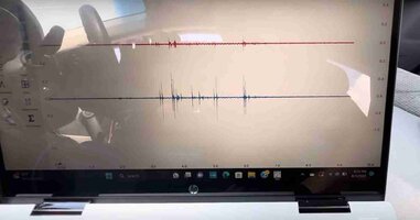
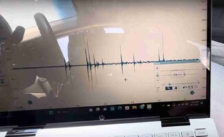
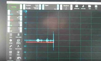
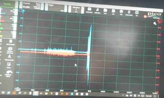
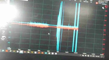
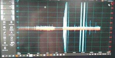
In the two following examples, the *Problem Wheel* was instantly identified by the dramatic and obvious increase in the Harmonic Amplitude of the Noise as the Vehicle was first making a Left Turn that showed up as a Gradual Increase in the Amplitude of the Left Wheel Noise (Blue Trace) during the Left Turn. The Red Trace is coming from the Right Wheel with the Sensor placed in the mirror position to the Left Wheel.
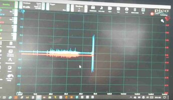
Then, the Test Driver made sharp Zig-Zags on the Highway at speed with the results of having the Blue Trace remain instantly Elevated with a slight break in between the two Vertical Trace Lines close together as the Steering shifted sharply from Left to Right. This Wave Form is distinctive as indicating that the Left Wheel was suffering from a Bad Wheel Bearing.
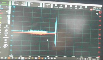
The sequenced images below emphasize the advantages of being able to Isolate the Noise in a Dynamic Driving situation... without ever having to Touch Your Tools:

DONTGUESSTEST2.jpgDONTGUESSTEST3.jpgDONTGUESSTEST4.jpgDONTGUESSTEST4A.jpgDONTGUESSTEST5.jpgDONTGUESSTEST6.jpgDONTGUESSTEST7.jpgDONTGUESSTEST8.jpgDONTGUESSTEST9.jpgDONTGUESSTEST10.jpgDONTGUESSTEST11.jpgDONTGUESSTEST11A.jpgDONTGUESSTEST12.jpgDONTGUESSTEST14.jpgDONTGUESSTEST15.jpgDONTGUESSTEST16.jpgDONTGUESSTEST18.jpgDONTGUESSTEST19.jpg
 

Attachments

  • DONTGUESSTEST17.jpg
    DONTGUESSTEST17.jpg
    43.1 KB · Views: 2
Last edited:

mrrsm
Original poster
Lifetime VIP Donor
Supporting Donor
Member
Oct 22, 2015
8,267
Tampa Bay Area
*Amplifying* (Pun Intended here) upon the information covered in Post #85 & #86... I thought I would array TWO "Joe's Auto Electric" Magnetically Held Vibration Sensors along the Back-Plane of my Ceramic Painted Oven Deck along with a few of his VERY Handy -2 - Have Neodymium Magnetic Oscilloscope Leads Holders that would be necessary to array them on say... under the Steel Frame-Chassis Sections or Stuck to the Brake Assembly Dust Plates on the backs of any of the Four Wheels... or underneath the Suspension, Engine or Transmission Mounts Steel Brackets... or Wherever You NAME IT.

VIBSENSORWITHMAGHOLDERS1.jpgVIBSENSORWITHMAGHOLDERS2.jpgVIBSENSORWITHMAGHOLDERS3.jpgVIBSENSORWITHMAGHOLDERS4.jpgVIBSENSORWITHMAGHOLDERS5.jpgVIBSENSORWITHMAGHOLDERS6.jpgVIBSENSORWITHMAGHOLDERS7.jpgVIBSENSORWITHMAGHOLDERS8.jpgVIBSENSORWITHMAGHOLDERS9.jpgVIBSENSORWITHMAGHOLDERS10.jpgVIBSENSORWITHMAGHOLDERS11.jpg


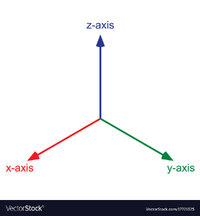
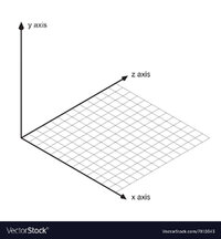
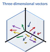
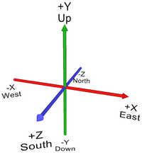
Getting this Inexpensive Support Hardware and Using these Tactics for deployment of them on or under your vehicle(s) is all very necessary *IF* you intend upon making ANY serious efforts at conducting Automotive Vibration Analysis in ANY of the Three Degrees of Freedom of Motion in The "X"... The "Y" ...or The "Z" Vectors (or any combinations in between) that Automotive Components can create... simply by using YOUR Oscilloscope for such Diagnostics:

3d-axis-colored-on-white-background-vector-17721325-1748973208.jpgdirection-of-x-y-and-z-axis-vector-7810343.jpgPicture4-2-2854812179.jpgproxy-1202936953.png

Beyond post-inspection observations of clearly Broken Components, I don't care HOW sensitive and subtle you MIGHT think that your "Inner Ear gauge & Meter" or your "Seat-Of-The-Pants" Vibration Detection Apparatus might be... I defy ANYONE to explain precisely Which Components (or any combinations thereof) is (are) either causing or contributing to the creation of Mysterious, often Impossible to Locate Vibrations and the Strange Noises they can generate... with any True Degree of Accuracy.

All that said... if you possess either a One, Two, Four or Eight Channel Oscilloscope and THIS Gear... then you can isolate certain suspect components in their Proper X,Y & Z Vectors of Motion... and THEN your Oscilloscope Screen WILL reveal whatever activity is actually taking place.

Now, while I honestly don't believe that it is necessary to take the MIT Mechanical Engineering Course shown in this Linked Video to understand the basics of all this stuff... I suspect that if you have the wherewithal to be reading THIS Topic right now... then you have already Drunk The "O" Scope Kool-Aid by now and are neither afraid to TRY TO DO NEW THINGS, nor afraid of LEARNING HOW TO DO NEW THINGS... and You've already done so ...time and again!.

Nonetheless... Please... Give this Low-Key (BUT Very COOL) MIT Professor half-a-chance at around 34 Minute into his Lecture and you'll be surprised at just how much of what he describes to his students ....is already nested within your Mechanic's Mental Wheelhouse of Understanding:

MIT Mechanical Engineering Course on Vibration:
Covering A Single Degree of Freedom


Vibration Isolation:


Also... Attached below is another "On Topic" White Paper worth digesting that provides even more insights into Vibration Diagnostics and Analysis:

In the end... Even if you NEVER delve any deeper into this subject than simply placing your Oscilloscope Vibration Sensors 'hither and yon" ... BUT... carefully observe WHERE and observe WHICH VECTOR(S) (X.Y,Z) they wind up being properly situated (pointed) at upon or near to each Suspect Component ....then your Oscilloscope WILL display them as Amplitude vs. Frequency Over Time and THEN you will EASILY figure out the problem from watching "ALL THOSE SQUIGGLES" on your Screen...WHAT Component(s)n are causing the Problems and showing WHEN they started to FAIL (at Certain RPM... During Certain Braking Events... in Certain Gears, Etc.)

THIS Process is a MUCH better approach than merely GUESSING and THEN wind up Buying Suspension Parts, Etc... and LATER finding out that what You THOUGHT were the *Problem Parts* or components turned out NOT to be what was Causing all that RACKET and all those Premature Parts Failures. :>)
 

Attachments

  • 0901d196801082e3_pdf_preview_medium.pdf
    318.8 KB · Views: 1
Last edited:

mrrsm

Original poster
Lifetime VIP Donor
Supporting Donor
Member
Oct 22, 2015
8,267
Tampa Bay Area
I'm always looking for the Ways & Means to invite Folks interested in becoming Good Diagnostic Technicians using Decent Bi-Directional Scan Tools to Join In... and get up close and personal with the "EFFECTS" of problem Engines...and then following on with using the Oscilloscopes and/or Sensitive Digital Graphing Multi-Meters to Dial in on the "CAUSES" versus just reflexively "Throwing Repair Spaghetti Against The Wall ...and just Hoping That Something Will STICK..."

In THIS Video...We get introduced to a Dude who should be YOUR Favorite Kind of Technician... Somebody who "HAS the "GEAR" ...WITHOUT The "Fear"...of FAILURE... that can come along with being intimidated by such seemingly too sophisticated Instrumentation. So HIS approach is to USE THE POWER OF THE ON-SCREEN VISUALIZATIONS ...and just SEE The Problem for What It IS.

The Customer Complaint Work Order Data:

NISSANVERSAMISFIREWORKORDER.jpg

The Average Dude with just a DMM and a "Surface" Lighted Probe will NEVER improve his Diagnostic Skill Set because he will Never be able to SEE enough DETAIL to Know what the Actual Problem Really IS ...but by the same token...The Average Mechanic with even a modicum of patience and interest CAN become a Competent Diagnostician once he KNOWS WHAT HE IS LOOKING FOR.

This Man Demonstrates doing just THAT on a Mid-2000 Nissan Versa sporting a Bad Misfire on Cylinder #3 using the Latest FREE PICO-Scope Version 7 Software (I prefer Version 6) and employing TWO Digital Oscilloscope Input Signals using a Paddle Style Ignition Coil Sensor picking up Secondary Ignition Coil Readings placed over the #3 Coil on a Four Cylinder Engine on Channel 1 with an In-Series 20:1 Voltage BNC Attenuator attached in line to prevent High Voltage (KV) from Damaging his Equipment...AND...while stringing a VERY LONG Channel 2 Lead back to the Tail Pipe to pick up the Engine Exhaust Pulses using a "First Look" Probe inserted therein.

So... Download, Save and Review THIS Video if you are sitting on the fence about getting a Basic, Inexpensive Oscilloscope (Well Documented by Price and Features listed at the Beginning of this Thread)...but have any doubts left about WHY You would want to try this *Stuff* Out.

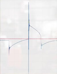
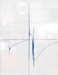
Stop... Look... and Listen... to his Explanations as he Breaks Down of the Coil Over Plug Wave Form's appearances between What a Known Good Wave Form Looks Like versus What a Bad Wave Form on the #3 Cylinder Looks Like that he can CLEARLY see on his Laptop Screen via the Features of the PICO-Scope Version 7 Software. AND SO...WILL...YOU.

Take note of just how MUCH DETAIL is being captured for later ZOOMED ANALYSIS that tells the story of what has gone wrong ...in EXQUISITE Detail... by a Guy who just wants YOU to SEE WHAT THE PROBLEM IS... JUST BY LOOKING AT THE PICTURES AND COMPARING ADJACENT CYLINDER ACTIVITIES ON SCREEN:


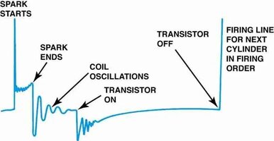
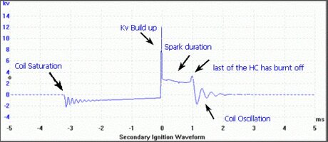
Secondary Ignition Trivia:

 
Last edited:

mrrsm

Original poster
Lifetime VIP Donor
Supporting Donor
Member
Oct 22, 2015
8,267
Tampa Bay Area
Paul “Scanner” Danner’s “No Spark” Diagnostics Testing Videos answer the Question of:

“Can I use an Incandescent Probe Light to investigate a “No Spark – No Start” condition like on a conventional Ignition System...on any COP (Coil Over Plug) System?”

“No. Nope… You Can’t… You’re Gonna Need A ‘SCOPE!”

Here are the Live Premium Pal “Scanner” Danner Training Sessions that EXPLAIN WHY This is True:

Part 1:

Part 2:

Recommendation on HOW to Learn MORE in concert with his FREE Premium YT Training Videos?

Visit THIS Link…

https://gmtnation.com/forums/thread...r-engine-performance-diagnostics-bible.23489/

If YOU need ANY Other CONVINCING that in order to become a Decent Automotive Diagnostician instead of remaining an “Accidental Fixer via Parts Changing…” Download, Save and Re-Watch THESE Two Videos for ALL of the Guidance in the Right Directions on this matter…. There is Just So Much To Learn Here !!!
 

mrrsm

Original poster
Lifetime VIP Donor
Supporting Donor
Member
Oct 22, 2015
8,267
Tampa Bay Area
I'm always looking for New Visual Training input on the subject of encouraging the Use of ALL variations of Oscilloscopes for Automotive Diagnostics. Recently... while trying to assist another GMT Nation Member... I found TWO such Videos that work 'Hand In Glove' to explain the Primary and Secondary Ignition Wave Form Analysis of a Coil Over Plug system in order to discover the "WHY" that is behind the incidence over Ten Years that a GMT360 Vehicle should suddenly "Die At Speed" due to ... "WHAT?"

In this instance, it was because The PCM, The COPS and The EFIs are all served by the Single, Failed Fuse #28 that SUDDENLY BURNED OUT... Perhaps even as a Protective Reaction from the PCM to a DEAD SHORT INSIDE OF ONE COP.... These Videos explain everything you need to know and understand... in Superb and Exquisite Details:

"WHY Does a Failing EFI Cause a FAILED COP...to DEAD SHORT and Shut Down The Engine?"

From Paul "Scanner" Danner Teaching a Wave Form Class at Rosedale College:


From Duane...of the "RealFixesRealFast" Youtube Automotive Training Channel:


Wanna Learn a LOT MORE about How to View and Interpret Automotive Wave Forms? Well... Okay then... Download BOTH of these Videos and spend some time Watching... Listening... and Learning The Ropes of Automotive Wave Form Analysis from Two of some of the BEST Automotive Instructors on The Internet!

PS...

This may seem a bit over done...but since Duane from "RealFixesRealFast" was explaining the relevance of understanding "Ohm's Law" in relation to the Ignition Components involved in the Ignition Circuit... Viewing and Downloading this 1943 U.S. Navy WW2 Era Electronics Training Film on the subject of "Ohm's Law" bears your observation and understanding... including whenever using Oscilloscopes in Automotive Diagnostics:


Also... If we concentrate our efforts at learning what JUST ONE WAVE FORM Looks Like...We can get lost in the weeds over the fact that ordinarily EACH Wave Form bears its own Wave Form Characteristics unique to either the Different Modules or its Related Components (such as a COP AND its Companion Spark Plug). "Scanner-Danner" demonstrates How To Analyze a Fuel Injector Wave Form in this last Video. Make some mental notes of The Differences you will see between a COP Wave Form shown in his prior Video and the EFI Wave Forms he demonstrates below:


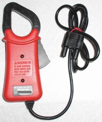
With a little practice using your OWN Oscilloscope on your personal vehicles.... you can use the High and Low Amp Clamp and other Oscilloscope Induction Sensing Tools to View your Engine Components in action during Idle and Snap Throttle Events and Record, Save and View them with further study.

Making Comparisons between how each Cylinder behaves depending upon their related Module Performances will allow you to KNOW what the Good Wave Forms vs. the Bad Wave Forms should look like....and you won't need to "Turn Wrenches" to do so!
 
Last edited:

mrrsm

Original poster
Lifetime VIP Donor
Supporting Donor
Member
Oct 22, 2015
8,267
Tampa Bay Area
And..THIS is "The BIG One"... *The Silver Tuna* of Secondary Wave Form Diagnosis Training that is almost a Decade Old... done at a PAY FOR ATTENDANCE CLASS that covers almost Two and One Half Hours of Instruction... and that probably allowed the Folks who showed up and paid close attention to FINALLY EARN BUCKETS OF MONEY...at the Shops where they already HAD Oscilloscopes available (Built-In) to many of their Shop Owned Snap-On Modis and other Higher End Scan Tool Systems... BUT THEY NEVER, EVER TRIED TO USE THEM!!!

THIS Guy... Jim Morton... Puts on a Yeoman's or Journeyman's College Course during this amazing Class on How To Interpret Ignition Wave Forms...and if YOU follow along and have not as yet obtained your OWN Inexpensive Oscilloscope for improving your ability to externally Diagnose Drive-ability and Engine Malfunction Problems... then you WILL want to GET ONE ASAP... as soon as you get THIS set of Instructions well seated inside of your Mechanics' Minds. Even if you don't save ANY other Instructional Videos previously mentioned in this expansive Thread on Oscilloscopes ...Please... By All Means... DOWNLOAD AND SAVE THIS ONE!


mrrsm

Original poster
Lifetime VIP Donor
Supporting Donor
Member
Oct 22, 2015
8,267
Tampa Bay Area
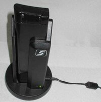
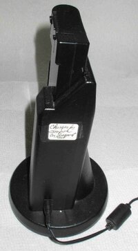
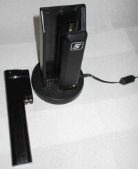
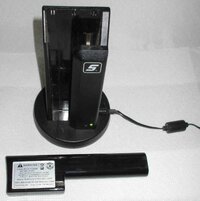
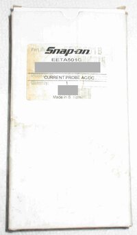
While "Lurking On eBay"...I recently lucked into finding TWO Bargains in support of my Oscilloscope(s) and in particular...these are complimentary for the Snap-On Professional Grade Scan Tools:

For Charging the Unique Batteries for the Snap-On Vantage Pro Diagnostic Tool ($88.00):

SNAPONBATCHARGER1.jpgSNAPONBATCHARGER2.jpg
SNAPONBATCHARGER3.jpgSNAPONBATCHARGER4.jpg


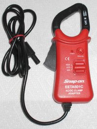
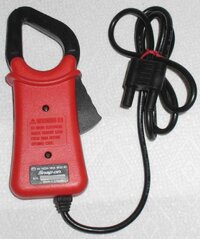
For Measuring HIGH AMPERAGE in Automotive Diagnostics for the Snap-On Modis and Vantage Pro Scan Tools ($85.00 vs. the usual $300.00 Cost)

SNAPONHIAMPCLAMP1.jpgSNAPONHIAMPCLAMP2.jpgSNAPONHIAMPCLAMP4.jpgSNAPONHIAMPCLAMP5.jpg

And...Since the idea here is that for Ordinary High Amperage Circuits, such as when engaging the Ignition ON and using the Starter Motor for the purpose of Conducting a Relative Compression Test... (with the FUEL or IGNITION Disabled) THIS 400 Amp Clamp is PERFECT because of the Extra Long Cord and having the Mated 4mm Dual Banana Plug for attaching it to an Oscilloscope (Snap-On Modis, Verus, Vantage Pro...etc.) and then taking a Current Reading from around either the Positive or Negative Battery Cable... AFTER... Turning on the 9 Volt DC Battery Powered Clamp and ZERO-ing Out the Tool via Adjusting the Upper Right Dial:

This is a similar model Snap-On High-Amp Clamp being used in a British Repair Shop in this very appropriate "Universal Relative Compression" Test Demonstration:


And...to perform this Diagnostic WITHOUT a High Amp Clamp...with a High End Snap-On Scan Tool...This Alternative Method WILL Work:


And Finally... Some Sound Classroom White Board Theory on this Topic:

Look for an EXCELLENT Relative Compression Wave Form captured from a 2005 Colorado 5 Cylinder 3.5L Atlas Motor at around 21:00 Minutes into this Video and immediately after that is an image of a 2007 Cadillac STS 3.6L Engine suffering with Single Bank Timing Chain Issues showing up CLEARLY on this initial, Non-Invasive Test as a BAD WAVE FORM.


As a Post Script... @m.mcmillen has a LOT of experience with performing the very involved, PITA Timing Chain R&Rs on these 3.6L Engines.
 
Last edited:

mrrsm

Original poster
Lifetime VIP Donor
Supporting Donor
Member
Oct 22, 2015
8,267
Tampa Bay Area
This Diagnostic Series should be the Object Lesson required for anyone intent upon becoming a TRUE Diagnostician. But... before I ask you to FOCUS ON THE OSCILLOSCOPE SCREENS… I must “Cut To The Chase” and do these Reveals UP FRONT:

(1) You CANNOT Diagnose Modern Automotive Systems without having access to the Proper Diagnostic Tools and Gear.

(2) You CANNOT Diagnose Modern Automotive Systems by COMPLETELY RELYING on Tools.

(3) You CANNOT Diagnose Modern Automotive Systems by ABANDONING LOGIC AND COMMON SENSE.

(4) You CANNOT Diagnose Modern Automotive Systems WITHOUT KNOWING HOW THEY WORK.

(5) You CANNOT Repair Modern Automotive Systems... by simply THROWING PARTS AT THEM.

(6) You CANNOT Diagnose & Repair Modern Automotive Systems if you DON’T SEE THE OBVIOUS SIGNS OF PROBLEMS OR SUFFER FROM OBVIOUS FAILURES OF IMAGINATION.

The Issues:

The Owner purchased his 2007 Cadillac Escalade at an Auction House and found Intermittent ABS Issues along with CAN Bus Issues. He took it to a Dealership and opened his wallet eventually to obtain an enormous number of Modules and Components with the idea of simply replacing parts hither and yon to no ultimate successful effect.

Finally he decided to take the Escalade on a Five Hour Drive from New York City out to “Crazy Ivan” at The Pine Hollow Auto Diagnostics Shop in Rural Pennsylvania, The Vehicle broke down en route and the Owner had to pay for the Truck to be towed the rest of the way to PHAD.

The Tools:

In addition to learning and appreciating the “Universal Step By Steps” requisite in ALL Proper Diagnostician approaches… Ivan employed the following Basic & High End Diagnostic Gear:

(1) A PICO-Scope Pro Version (4XXX Series) Automotive Oscilloscope (Leads and Needle Probes).

(2) Laptop Computer with FREE PICO-Scope Ver. 7 Automotive Software Suite.

(3) A High End Bi-Directional Diagnostic Scan Tool.

(4) Two Different DMMs with AMP Clamp to measure CAN-Bus Ohms (2 X 120 Ohm Resistors)

(5) Lighted Pin Probe.

(6) ALLDATA Access with 2007 Cadillac Escalade Circuitry Print Outs.

(7) A Bright Head Band Flashlight.

(8) A Note Pad, A Pen, and a Common Sense DIAGNOSTIC PLAN.

(9) A DLC “BOB” (Break Out Box).

The Ultimate Solution to The Problem:

After following an Organized, Step By Step approach, eventually Ivan discovered that the High Speed CAN Bus was being interrupted from the Normal Ohms level at the Pin 6 and Pin 14 o the DLC Reading which should --always-- be at 60 Ohms… (+) or (-) a Few Ohms... only to be intermittently reading 120+ Ohms due to: The Transmission Harness Wiring rubbing through on the Passenger Side of the 4L60E Transmission ...SHORTING OUT THE HIGH SPEED CAN BUS ON CAN-LOW BEING PULLED DOWN.

Part 0: Preliminary Look at the 2007 Cadillac Escalade CAN Issues


Part 1: 2007 Cadillac Escalade on a CAN-Bus Escapade


Part 2: 2007 Cadillac Escalade on a CAN-Bus Escapade

 
Last edited:

Forum Statistics

Threads
23,722
Posts
642,618
Members
19,256
Latest member
Tor76

Members Online