Good Morrow... One and All...
Please consider what follows as a sort Text & Visual
"How to Re-Build the 1998-2002 Chevrolet Camaro-Firebird LS1 Emergency Brakes: Class-101" as its doubtful that the ways and means for preparing how to tear this assembly down and re-building it correctly versus paying nearly $200 Per Wheel for Brand New E-Brake Hardware has ever been done to the scale of the included minutiae. As such the "Follow-The-Steps-In-The-Imagery" method of learning consists of
75 Separate Photos... I had to park these images on my Photobucket.
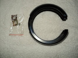
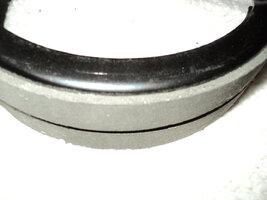
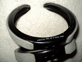
If you are intent upon doing this properly... Try to obtain AC-Delco or Delphi components when and where possible. It will be necessary to submerge the entire set into a pan with enough of a powerful De-Greasing agent that it will dissolve perhaps as much as 20 years of dirt and corruption. But prior to dropping the assembly into the pan... you must first remove the "C" Drum by unfastening the Spring Clamp holding the inner race of the Black Metal Inner Hollow Drum Bracket at the top of the unit. Then ...watch your hands and fingers carefully here... while pushing the "C" Drum downward, observe that it will easily slide down and free from the two contact ends off of the Lever Pins Pads at the bottom of the unit. Don't re-use this "C" Drum and instead, it should be discarded in a responsible manner as it represents a present danger from Mesothelioma Lung Disease should the Old E-Brake Dust on it become dislodged and inhaled.
After soaking the E-Brake assembly for a while, unscrew or undo any other components attached to the Hot-Dipped- Zinc-to Cast-Iron base and then begin scrubbing the base and components either in a heated Ultra-Sonic Machine such as the Umaxx or obtain some large Brass Bristled Brushes and some Green Scotch-Brite along with some Dawn Dish Soap. Diligently scrub each and every part free of all dirt, crud, corrosion and rust and then rinse each item individually in Very Hot water and pat dry them with paper towels while they are still warm.
You will use up quite a few Paper Towels during this job, so keep the roll handy. Start by working on the base to clean out every last crevice of old grease, dirt and rust after removing the "Tin Shield" and setting it aside. Use a screw driver to dig and probe around inside the heavy cast cylinder and remove any debris or junk lodged therein. After you have ensured that all your hardware is spanking clean, begin by slipping the drop-forged Emergency Brake Cable Armature into the body of the cylinder. When you later re-install the Machine Screws with the Combination Hex and #2 Phillips features into the ancillary attachments... put a drop of Red Thread Locker on them and snug them tight.
There is only one way this item will insert, so be patient and look at the re-assembly images attached here for guidance. After that, install the new Weather Boot onto the base with the thin tin hold down oval ring with the two end screws as this rubber item will hold the armature essentially right where it needs to be for the ease of the rest of the build. The rest of this How-To is all visual....Please...Look at the pre-assembly layouts and lubrication imagery and simply do what you see in the photos as they are a good guide to ensure that everything goes back correctly as follows. The last few images here show how the lever Armature actuates the "C" Drum by uniformly expanding it outwards to make contact with the smooth inner race of the Rear Disc Brake to stop or hold the vehicle from moving by means of internal friction:
The next installment will show this E-Brake Unit being manually pre-set with Vernier Calipers and adjusted with the use of a flat-bladed screwdriver. Then the E-Brake assembly will be inserted into Rear Brake Disc bench mounted in a large vice and "image-documented" in the like manner as follows:
http://s557.photobucket.com/user/60dgrzbelow0/library/1993 CAMARO Z-28/93Z28SUSPENSIONANDBRAKES?sort=2&page=1


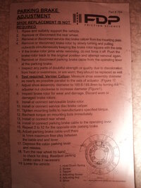
 It should hold it when in gear at idle. If it don't, readjust.
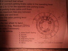
 qwAAOSwyTZUWjff&vxp=mtr