NEED HELP Front pass & rear driver side window switch lights dead

SpitShine_PL

Original poster
Member
May 26, 2023
49
Poznan, Poland
Long time no posting, but my truck is fine and has been puttering along daily (in Europe... without a CNG/LPG conversion, with insane gas prices, har har har!)

It's super weird to type this, but it was only during a drive last night that I noticed the front passenger and rear driver's side window switches are dark. The driver's window switch panel, the rear pass window switch and all other switches light up nicely.

I figure this means both affected switches have the light sources dead of age or there's something funky going on in the wiring.

I understand all backlight sources in the window switches (plus other switch panels, like the garage opener) are fed via several brown wires coming from the left I/P fuse block (10 amp fuse, INT PARK) and are triggered the PARKLAMP RELAY (which itself is powered by a 30 amp fuse labelled PARK LPS that lives in the UEC). If the fuses were blown, no backlights on the listed components would come up with interior lights/triggered by the headlamp switch turned on.
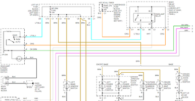
Screenshot 2024-10-20 090238.png

I could confidently test the brown power wires feeding the affected window switch lights with a test light, I suppose, to verify they get their 12 volts. Otherwise I would have to take the affected switches apart and replace the light sources.

1. Can the window switches be disassembled safely without irreversibly breaking them?
2. What are the window switch light sources? I understand the backlighting is indirect and works with a single bulb on the switch PCB. Are they T-size wedge-lock bulbs, like the 3 or 3.5-mm white ones? IDK if GM used soldered in LEDs in the window switches.
 

Mooseman

Moderator
Dec 4, 2011
26,000
Ottawa, ON
1. Can the window switches be disassembled safely without irreversibly breaking them?
Yes. Done all the time to replace the bulbs inside.

2. What are the window switch light sources? I understand the backlighting is indirect and works with a single bulb on the switch PCB. Are they T-size wedge-lock bulbs, like the 3 or 3.5-mm white ones? IDK if GM used soldered in LEDs in the window switches.
They care controlled by the BCM via PWM according to the input from the IP brightness adjustment just below the headlight switch.

More than likely, you didn't notice it and they are now dark. Likely just the bulbs inside are burnt. The usual remedy is to replace the bulbs with LEDs.
 

SpitShine_PL

Original poster
Member
May 26, 2023
49
Poznan, Poland
Aight!
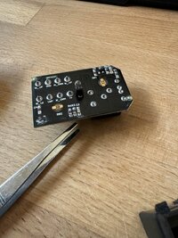
BTW, found a dead rear window switch for the Suburban and prised it open to see if the bulb is replaceable.
Well, just my luck * sobs *. The thing is THT soldered...

Any particular advice on the soldering iron tip and soldering temperature setting? I'm kinda proficient, I'm just careful about anything related to PCB soldering.

IMG_0844.jpg
 

Mooseman

Moderator
Dec 4, 2011
26,000
Ottawa, ON
@Blckshdw is our resident LED conversion SME. We do have a big LED mod thread that might have those answers, and others.


Blckshdw

Moderator
Nov 20, 2011
10,747
Tampa Bay Area, FL
Any particular advice on the soldering iron tip and soldering temperature setting? I'm kinda proficient, I'm just careful about anything related to PCB soldering.

You won't damage the PCB, it can handle the heat better than the LEDs can. Treat it as you normally would, and you should really be fine. In some cases where the OEM solder doesn't plan nice and melt, you may need to buy a small quantity of low-temp melt solder to help out. I haven't run into that scenario on components in these trucks though. :twocents:
 

SpitShine_PL

Original poster
Member
May 26, 2023
49
Poznan, Poland
Alright, to wrap this up nicely:
The bulb swap was easy as a walk in the park, with the right tools.

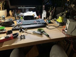
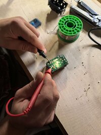
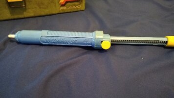
I have a 5 Ah Ryobi battery powered "desk" soldering iron (honestly, any soldering iron, even a corded one -- with a pointed tip WHICH IS CLEAN -- will do), a solder sucker (which is essential for this type of job) and a soldering fixture (you can use a small vise, if you got one, it's enough). I also had a 12VDC bench power supply to test the new bulb post-install. If you don't have one, use a multimeter that can test continuity. The rear window switches for the 2002 Suburban have the pin legs that mate with the harness plug in the doors labelled on the PCB, take the black test lead to GND and the red test lead (positive/12V) to LMP. The bulb should light up.

462554802_1110886933978866_7773086562517882084_n.jpg

462574669_897515548642865_4397981988381787072_n.jpg

You just need to fix the PCB in the fixture/vise and melt away the solder where the bulb legs stick out, preferably both THT solder points at the same time, while gently pulling out the bulb. It takes a bit of patience and coordination. Preferably, grasp the bulb with your fingers and try to wiggle it out while heating up the solder blobs that bind the legs to the PCB on the opposite end. You can use tweezers, but do not use ANYTHING that increases the leverage, like long-nosed pliers or a multitool, or you break the bulb and need to vacuum clean your bench (ask me how I know, LOL).

When the bulb is removed, take the hot soldering iron tip to each THT hole in which the bulb legs lived from one side of the PCB and put the nozzle of the solder sucker as flush as possible at the same hole on the other side of the PCB. When the solder in the hole starts to melt, trigger the sucker to aspirate the molten solder away. You need each hole to be clear of solder (see if the light shines through the hole). The rest is easy, drop the new bulb's or LED legs through both holes, bring the bottom of the bulb/LED snugly to the PCB surface and bend away the legs sticking out on the other side of the PCB outward from one another. Apply a small blob of solder to each hole to secure the leg wire. Try to keep the blobs of both legs separate. If you feel like the gap between the blobs is too narrow, you can isolate the blobs, electrically, using anything on hand, like a small dab of RTV (I used black polyurethane nail polish, LOL).

Now, you may hit a snag during this job.
For me, the worst part was to strip down the front passenger side window/door lock switch panel.
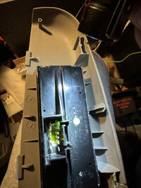
It seems that during the factory assembly of this part they soldered the PCB pins for the harness plug and IMMEDIATELY put the PCB into the black housing. This way the PCB pins melted the slots in the housing bottom and got stuck. You can find this out by just how hard it is to separate the top and bottom halves of the housing. If the pins seem to be stuck in the bottom part of the housing, well... Creative destruction is in order. Just don't break the damn PCB or use any metal tool to prise the PCB from the bottom part of the housing (you will wear down the PCB resin that seals the electrical paths; if this happens, don't worry -- as long as the metal path is not broken, you can "reinsulate it" using e.g. polyurethane nail polish).

I had to break away the bottom of the well which receives the door harness plug just to let the PCB legs come out of the black bottom half of the switch housing. Don't worry about it. Just don't break off the PCB pins and if you bend them in the process, straighten them out with narrow nose pliers.

IMG_0858.jpeg

The front passenger side switch assembly has a big piece of transparent plastic that is a light guide for the door lock and window switches. Remove it from the bottom of the PCB using a narrow flat screwdriver; once you replace the bulb/install a LED, reattach the light guide piece by inserting one leg into its hole (there are two of these), and take the same narrow flat screwdriver to the other leg of the light guide (the part is brittle, be careful) to pop it into its hole.

Reassemble, reinstall the Torx socket screws to secure the switch housing to the trim piece, and you're good.

You can secure the PCB to the bottom of the housing (with the part of the connector receptacle broken off, as in the picture above) with e.g. hot melt glue, tho it's not necessary. The PCB won't move inside the switch housing while reconnecting the door harness plug if you hold down the buttons on the top of the switch.

Done!

Note that unlike the rear door switches, the front passenger one DOES NOT have the text legend on the PCB for the legs, so it's difficult to test the new bulb connection continuity with a multimeter/12V bench supply without a circuit diagram on which you can find which wire color is LMP input power and which is the ground (GND). If you really want to know the pinout, you will need to inspect the respective harness connector in the front passenger door and reference the wires to the pins on the bottom of the door lock/window switch.
 
Last edited:

Mooseman

Moderator
Dec 4, 2011
26,000
Ottawa, ON
Nice! I also have that Ryobi soldering iron. Love it! I can take it anywhere and gets plenty hot.
 
  • Like
Reactions: SpitShine_PL

SpitShine_PL

Original poster
Member
May 26, 2023
49
Poznan, Poland
TBH, I wanted to go Team Milwaukee, but the form factor of their battery solder is reportedly unwieldy... Not a good choice if you got literally dozens of yards of wiring to solder, as was the case with my truck, LOL!
 

Forum Statistics

Threads
23,667
Posts
641,789
Members
19,099
Latest member
Bradykg69

Members Online