Drag racing the GMT360 with the LL8

mrrsm

Lifetime VIP Donor
Supporting Donor
Member
Oct 22, 2015
7,736
Tampa Bay Area
This is a Quote from a helpful, On Topic Article:

"O2 Sensor Mounting: The O2 needs to be mounted 6-8” after the merge in the header collector. It needs the tip pointed down at least 10 degrees from horizontal and at least 15 degrees from vertical I prefer about a 45 degree angle from horizontal. You should then have at least 18-24” of pipe after the sensor. If you have any exhaust leaks between the combustion chamber and 18-24” after the sensor you are going to have problems."

Source:


rchalmers3

Original poster
Member
Jul 11, 2020
207
Irmo, SC
Thanks for digging that up! My goal was to have the least amount of pipe needed, so that the three bolts pinching the pipe to the manifold would fix the pipe in place without any additional brace. I may up fabbing a brace anyway, especially if I have to add more length. For now, I'm going to fit the pipe I created and will test it as is.
 

rchalmers3

Original poster
Member
Jul 11, 2020
207
Irmo, SC
Happy New Year gentlemen,

I have a question for those of you who are smarter and know more than I do. I intend to relocate the fuel tank and battery into the cavity behind the rear axle where the spare used to reside. Relocating the battery from it's OEM location creates the need for reconfiguration and rerouting of the positive battery cables.

My question is: Does the alternator feed need to go all the way back to the battery, in order to dampen it's electrical hash? Or do you think the ECM can handle whatever dirty output the alternator is producing?

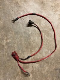
The minimal cable routing I'm imagining would be to use the battery cable post on the starter as a junction: a single power cable from the back of the car up to the starter, with cables from there leading to the alternator and body power panel respectively. I just don't have knowledge about whether this will create issues or not. Here is an image of the OEM cable for reference.
IMG_0400.jpg
Any experience or advise is appreciated.
Rick
 

Mooseman

Moderator
Dec 4, 2011
25,344
Ottawa, ON
I don't think it would make much difference. Lots of factory cars, including my Caprice PPV, have trunk mounted batteries. The main cable goes all the way to underhood where it's branched off to the starter and a post for everything else to hook into. I'd go one wire size bigger just to be sure the increased distance doesn't increase amperage loss during cranking.
 

rchalmers3

Original poster
Member
Jul 11, 2020
207
Irmo, SC
I don't think it would make much difference...... (t)he main cable goes all the way to under-hood where it's branched off to the starter and a post for everything else to hook into.
Thanks for the apparent evidence for not needing the battery to be an electrical damper.

I'm no expert, so I'll poke around the 'net a little bit more today to see if my concern is unfounded.

Rick
 

FloMaxSS

Member
May 24, 2021
18
Maryland
Happy New Year Rick! Gas tank, radiator and battery locations are things I've racked my mind about too. I wish I had pictures but not enough time. Here's what I resolved to do.
Like you, I too wanted gas tank as far back as possible. I started to use a nice aftermarket plastic 10g tank and mounting just behind rear axle, high up as possible.. Then added E85 to the build and went with a 14g steel tank for a 1940 chevy i believe (I can verify for you if needed).. fits perfect once I cut out the rear drop cubby and made rear floor flat. I still have plastic tank with a modified trailblazer fuel bucket with walbro 450 installed.. just didnt make seals or bolt together yet.. Let me know if you're intertested in these and I can take pictures.. I would just give you the plastic tank if you paid shipping.
Mounting the radiator somewhere towards the back would in theory shift more weight rear. However, you would be adding a lot more weight in big thick rubber hose, fan wiring, etc. just to get it there. Your fan would run constantly because there would be no open air source when not moving and no airflow when moving (not as much concern for drag race but still). Would probably need to run bigger fan or 2 fans. Will not be as efficient no matter what. As clean as your engine bay will look, the rad being in there won't be an eyesore.. the engine will still be the focal point. What I resolved to do here is keep rad up front but move it about 5 inches closer to engine, used electric fan, corvette belt spacing and moved rad mounts. Might not seem like much but rad/fan weight being 5inches less from front axle and 5 inches farther toward rear will make some difference. Not sure how much you could get away with for I6. I did try to move my trans cooler to rear with a fan and it always ran hot so I moved it back in front of rad and that alone dropped trans temps by 35 degrees. There are some reputable sources on ebay for good-looking, inexpensive all-aluminum rads for the I6, SS-ers use them too and make a modified lower rad hose.
Battery relocation to the rear was a viable option back in the day. The electronics were not as sensitive to voltage spikes. Best battery technology then required at least a 30+ pound battery to reliably start your race car and even with 12 pounds of extra wire that 30lbs was better in the rear. Now that we have 5-6 pound lithium batteries that will reliably start almost any gas engine for 10+ years, it would be counter-intuitive to use 12pounds of battery cable to mount 5lbs of battery in rear. I mounted a braille lithium just under the trans bellhousing using a custom aluminum cross-member (bottom of battery still higher than bottom of frame rails), replacing factory steel cross-member. Wire runs are stupid short so i could use smaller, lighter wire. <2' of 6ga wire to starter, 1' of 6ga from starter to alternator, 3' each of positive and neg 12ga wire from battery to ecu., 6ga. batt ground to engine block, 10ga batt ground to frame, all other grounds attach to engine block or heads. Any ECU, sensors or gauges MUST have positive hookup directly to battery! Negative leads for ecu, sensors or gauges must be grounded to neg battery post or engine block/heads. Any electric motor, simple switches, relays etc can be powered directly off alternator post, but not sensitive electronics. So my electric fan, electric water pump, fuel pump and relayed headlights and horn all get main power from alternator post and ground back to block; except for the fuel pump ground which because its at far rear grounds to the frame. Yeah my harness is fully custom from front to back but I've shaved tons of wire weight and cut my voltage drop to all components to less than half what stock was.
I'm trying to get ahead of you here so I don't get blamed for you having to re-do anything.. LOL Not that I'm an expert.. just already been down a similar path. Keep up the great work!! I'm learning a lot of new things from your build.
 
Last edited:
  • Like
Reactions: rchalmers3

FloMaxSS

Member
May 24, 2021
18
Maryland
Also, hope you figure out how to do lightweight roll-down windows using factory motors. It would probably have to be plexiglas instead of lexan so it didn't get scratched from repeated up/down. I've heard its harder to drill and cut so getting it fixated in factory window holder might be a chore.. If you could get these made for a fair price, you could sell hundreds of them. The only way I could delete ac is by keeping all 4 windows able to roll down. I can't wait to see how your rear hatch works out. At this point, lightweight windows are the only way I can shed any more weight and keep it street.
 
  • Like
Reactions: rchalmers3

rchalmers3

Original poster
Member
Jul 11, 2020
207
Irmo, SC
Hiya FloMaxSS, thanks for explaining some of your design and constructions. I appreciate hearing your thoughts on how to approach some of the design issues and potential impacts on weight.

Having read your ideas, I believe I will continue with my current plan. You mentioned you were fitting modern battery technology, but didn't mention the cost. My project has definite spending limits, so if I use some salvaged wire and a $30 used battery out of a wrecked Honda at the wrecking yard, I'm good! I may regret some of my choices later, but for now I will follow my ideas.

Responding to your post, I will add an update to the progress report.

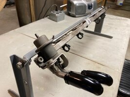
The assembly of the fuel system is underway. Thanks to @limequat for assisting me in selecting the right bits for solving some of the details in an affordable manner. I'll be using the early model fuel rail with integral regulator. Those are 90* adapters to 6 and 8AN fittings attached to the rail.
IMG_0430.jpg
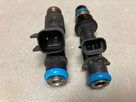
The fuel injectors I'll use are 80lb Deka units, and will be direct fit with the connector form that matches the later injectors, seen on the left.
IMG_0429.jpg
I have the fuel tank assembly prepared, with a Walbro pump and generic filler with out/in line fittings. The blue fitting is a roll over check valve.
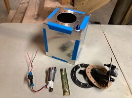
IMG_0422.jpg
Here it is mocked up. It is 640 cubic inches or 2.77 gallons in capacity. Less the pump of course!
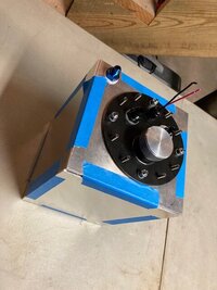
IMG_0423.jpg
With another acknowledgement to @limequat I have been purchasing the pieces needed for the electrical system, so at the moment I'm waiting for my credit card to cool down a bit before I purchase the injectors and PTFE fuel and vent hose.
Meanwhile, I thought I would assemble an IC water box, since I have the metal and wish to maximize air density to for realizing the maximum benefit of burning ethanol fuel.
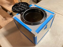
IMG_0426.jpg
I have contemplated the IC pump delivery and return details, but this system is not a priority. I can add the hose and vent bungs to the tank after the tank is welded. In the short term I will start by running the car at atmospheric temperatures by welding a MAF bung onto an inlet pipe.
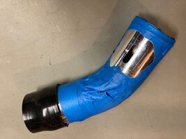
IMG_0424.jpg Another project I'm working on is to assemble another wire loom for the test platform, since the race car engine retained the first one I built. This is good indoor work for when it's cold and/or wet outside.
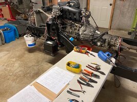
IMG_0428.jpg

I did have to disassemble my outdoor hoist for concrete repair. The concrete cracked under the column. Tightnening the anchor bolts did not solve the issue and the column was too loose for me to trust. I'm making this project a priority because I have a couple of small jobs that will produce income for my race car budget.
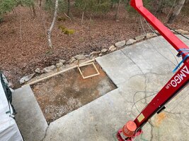
IMG_0432.jpg
That is my February update, with more to come as I discover more time and money.

Thanks fellas, I hope you are all doing well. Please comment and let me know your thoughts.
Rick
 
Last edited:

rchalmers3

Original poster
Member
Jul 11, 2020
207
Irmo, SC
Can't remember if I read about your rear axle plans.. Are you using the 8" or upgrading to 8.6" alumalite?
I dunno about it being Alumalite, but it's the slightly larger long wheelbase Trailblazer axle. As I recall, it's option code G86, with a limited slip arrangement. I fitted 4:10 gears in it, so hopefully it will work out.

FloMaxSS, what are you using for rims and tires? I need to start thinking about that detail, and I'm interested in what you are using.

Thanks,
Rick
 

mrrsm

Lifetime VIP Donor
Supporting Donor
Member
Oct 22, 2015
7,736
Tampa Bay Area
  • Like
Reactions: rchalmers3

Mooseman

Moderator
Dec 4, 2011
25,344
Ottawa, ON
I dunno about it being Alumalite, but it's the slightly larger long wheelbase Trailblazer axle. As I recall, it's option code G86, with a limited slip arrangement. I fitted 4:10 gears in it, so hopefully it will work out.
All TrailBlazers, AFAIK, never came with limited slip G86 diffs, only the G80 locker. However, you are right that the EXT came with the 8.6 which should help it survive depending on how much power you will be producing. If you grenade it, you might have to spring for a TB SS or 9-7x Aero 9.5" 4.10 diff which came with the 6.0L.

The G86 8.0" and 8.6" axles only came in the AWD variants of GMT360's like the Bravada, Rainier and 9-7x.
 

FloMaxSS

Member
May 24, 2021
18
Maryland
All info I could find is that all 8.6" axles used the AAM alumalite housing.. should have the casted ALUMALITE impression on the housing. The early 8" and the TBSS 9.5" are cast-iron housings and I've seen a few later 8" that used the alumalite housing. On my 09 SS AWD pushing 700 crank hp, I swapped out the 9.5" for the 8.6", cryo-treated 4.56 gears, detroit true-trac LSD, moser axles, so rear axle might see 500hp at the most and its held up flawlessly. I would think a good condition 8.6 w new gears will hold up fine for your application. Axles would be the weakest link, but you could always replace w moser axles if you did break one. I know this build is focused on drag racing but are you still keeping it streetable to and from the track? Not sure how much boost you are willing to shove into such a well-thought out motor, but I'm guessing a reliable output of 500hp? You could go a lot lower on the gears if you wanted to. 4.10's might have you 1000-1500 rpm short of redline in 3rd gear as you're trapping, the same thing happens to SS's at stock power levels w 4.10 gears.
This is a pretty awesome calculator for all trans and axle ratios:
What mooseman says regarding g80 vs g86 sounds about right.. never have seen g86 on any non-SS trailblazers. I've also never ran into any of the other AWD gmt 360 variants mentioned as they are really rare. The G80 might actually be the better stock choice for just drag racing, the g86 better for road racing. Or just go Lincoln Locker!
 
  • Like
Reactions: rchalmers3

Mooseman

Moderator
Dec 4, 2011
25,344
Ottawa, ON
The G80 might actually be the better stock choice for just drag racing,
I disagree about using the G80 for drag racing. They can only take so much and have been known to shatter the engagement system if too much power is applied at wheel spin, which is probably why they didn't use it in the SS.
 

FloMaxSS

Member
May 24, 2021
18
Maryland
I disagree about using the G80 for drag racing. They can only take so much and have been known to shatter the engagement system if too much power is applied at wheel spin, which is probably why they didn't use it in the SS.
Yeah, it is still a factory light-duty diff. from a durability standpoint. I was talking about the traction/hook of a locker vs lsd in these stock gmt360 apps. You're correct that a bonafide g86 would be less prone to breaking in a drag app. The G80 locker on a prepped track/slicks would allow for a more aggressive hook up until the point where it breaks. G80 is just GM code for locking diff.. the G80 in a 10.5" or 11.5" rear can take all the spinning and boosted launches of a duramax for decades. The G86/9.5/TBSS axle, in stock form, can take the abuse of a 1000hp boosted LS, but its a heavy pig.. it uses a Torsen LSD(no-clutches.) GM uses LSD's on all their performance apps because its more appropriate for a street-performance standpoint than a G80 locker (most people do not anticipate what happens when you mix high hp and rain/slippery conditions with a locker).
Come to think of it, I know the all the auto/LS2/SSR's used the alumalite 8.6 but used the same style Torsen LSD as TBSS's..
 
  • Like
Reactions: rchalmers3

mrrsm

Lifetime VIP Donor
Supporting Donor
Member
Oct 22, 2015
7,736
Tampa Bay Area
Thoroughly agree with @Mooseman in 'Shining On' this idea of ever using the Eaton G80 Locker for Drag Racing. This informative thread covers a lot of ground de-mystifying this Pumpkin with plenty of reasons why it earned the ignoble title of being "The Gov Bomb" mostly due to its ill-treatment during improper use:

 
Last edited:
  • Like
Reactions: rchalmers3

FloMaxSS

Member
May 24, 2021
18
Maryland
Thoroughly agree with @Mooseman in 'Shining On' this idea of ever using the Eaton G80 Locker for Drag Racing. This informative thread covers a lot of ground de-mystifying this Pumpkin with plenty of reasons why it earned the ignoble title of being "The Gov Bomb" mostly due to its ill-treatment during improper use:

Lots of good info in the linked post! That was a ton of research you had to do just to properly rebuild that axle. Thank you for reassuring me that I made the right decision to not rebuild my own axles and leave it to the driveline shop that has already done all the research. I've heard all the horror stories of the gov-bomb in the 10-bolts, but these issues are not as prevalent in the 14-bolt axles. That's why I put a Truetrac on all my 10-bolts.
Not endorsing the G80 in a 10-bolt by any means, but I stand by my statement that, up until it breaks, will provide a more aggressive hook than a g86.
Rick's build is somewhat budget-oriented so I was just helping to advise him on what he might already have or have inexpensive access to. He can get it running with whatever he already has and can switch-out to better diff/gears/axles later. A diff breaking isn't really a safety hazard.
Interestingly, GM is still using the mechanically locking style diff on all their new trucks. What are Ford and Dodge using nowadays?
 
  • Like
Reactions: rchalmers3

mrrsm

Lifetime VIP Donor
Supporting Donor
Member
Oct 22, 2015
7,736
Tampa Bay Area
Well... Not to "Drag" this subject along in Rick's Thread too much further, but for anyone curious as to precisely what "The Achilles Heel" REALLY is for the (14) Bolt GM Eaton G-80 M-Locker Differentials as well as for the (10) Bolt flavors found in the Trailblazers and Envoys...Observe Closely:


And just a footnote FYI... Ford and Chrysler never designed a Pumpkin quite like the GM Eaton G-80 M-Locker. :>)
 
Last edited:

rchalmers3

Original poster
Member
Jul 11, 2020
207
Irmo, SC
I mounted a braille lithium just under the trans bellhousing .....
Hiya @FloMaxSS
After nearly purchasing a used small car battery, I thought of this post and I am revisiting my idea of placing the battery way back behind the rear axle.

I am considering following your suggestion to mount a small, 4lb lithium battery close to the starter.
With the AC compressor removed there is ample space in that area. I can easily construct a battery mounting fixture that occupies that space.
Can you please send data on the battery you chose, and perhaps a few images of the install?

Thanks,
Rick
 
  • Like
Reactions: FloMaxSS

FloMaxSS

Member
May 24, 2021
18
Maryland
I'll try to get you images, but I'll give data for now.
My under bell-housing mount was made by simply replacing the steel front x-member (one that looks like channel with 3-ovals in it) with aluminum x-member. I used 1/8" 6061 T6 sheet pieces and tig-d it up. Think channel with longer lower leg for battery. Lots of ways you could skin this cat since you're tigging now. Just give a lot of diligence to prevent it from warping! Clearance between bottom of bell-housing to bottom of frame is just a tad over 4"

I consider the Braille Greenlite to be the safest and most reputable bang for your buck lithium battery. These are capable of lasting over ten years with proper charge maintenance. I know the cost is hard to justify, but I look at it as these are investment grade batteries.
G5S- 4.5x2.6x3.7" 2lbs 350 cranking amps each, $250, x2 or 3 of these will fit side x side under bellhousing
G20- 7x3x6.25" 4.5lbs 700 cranking amps each, $550, fits under bellhousing
G30- 6.8x5.2x6.9" 6.4lbs 950 cranking amps ea, $599, will not fit under bellhousing, but would fit in AC compressor area as you suggested.

For lead-acid types, AGM is the way to go and the 20lb EXL30 Deka batteries have the best rep for surviving in a spot where a bigger battery was originally spec'd. 3-4 years with proper charge maintenance. This would also fit in AC comp area.

On my AWD, for purposes of high compression, maximum longevity and moderate electrical load, I used x3 of the G5S.
On RWD, for puroses of high comp. and light-moderate electrical load, I used x2 of the G5S
On Vette, I used the G30
 
  • Like
Reactions: rchalmers3

FloMaxSS

Member
May 24, 2021
18
Maryland
Also, what are you doing for engine, trans, body mounts? I highly recommend solid mounting the engine and body and use polyurethane on the trans. You can also ditch a lot of factory body mount weight this way. Bonus is that you can body drop 7/16"!

You asked me about wheels/tires.. I need to know if this is going to be shearly a trailer queen, driven to and fro track.. ie 2 sets of wheels/tires? Is there any way that you will be able to tag this in SC?

What have you devised for suspension so far?
 
  • Like
Reactions: rchalmers3

rchalmers3

Original poster
Member
Jul 11, 2020
207
Irmo, SC
I consider the Braille Greenlite to be the safest and most reputable bang for your buck lithium battery.
Thanks, I'm currently (pun intended) interested in the G20 (L20) battery for my project. It is advertised as offering comparable CCA's in a greatly discounted weight and size.

I measured the max starting amperage on my two running Trailblazers, and on my tired old 2005 GMC Sierra 1500 with the 4.8L. The current draws ranged from 320 to 380 amps cranking. I'm unaware of how the engineers calculated the battery size, but it looks they spec'd batteries with a capacity of about 2x. Does that sound right to you? How did you match the batteries you used to your applications?

Rick
 
  • Like
Reactions: FloMaxSS

rchalmers3

Original poster
Member
Jul 11, 2020
207
Irmo, SC
Also, what are you doing for engine, trans, body mounts? I highly recommend solid mounting the engine and body and use polyurethane on the trans. You can also ditch a lot of factory body mount weight this way. Bonus is that you can body drop 7/16"!

You asked me about wheels/tires.. I need to know if this is going to be shearly a trailer queen, driven to and fro track.. ie 2 sets of wheels/tires? Is there any way that you will be able to tag this in SC?

What have you devised for suspension so far?
The body mounts are two part plastic pucks, (pad + the double D through frame section, fastened together) with the pad portion cut down to a minimum to just clear the frame. I also eliminated 4 of the mounts so that the body (less the front clip) is sitting on 6 mounts at the A, B and D positions.

Engine and trans mounts are stock stuff. It did not occur to me to mess with those. What would be the benefit?

$prings and $hocks are TBD after getting it rolling and weighed. That's gonna hurt, I reckon.

I don't have any dreams or illusions about driving this abomination on the road. I need to fit some brake rotors and then see how the rear axle sits under the body while lowered. If I need to center it with an adjustable pan hard, I'll do that and then measure for a max tire width. If I can run the stock 17" rims in the rear I'll like to do that. Up front, I'd like to run skinny rims and tires, but at first glance, it looks like I would need to cough up even more major coin to source the wheels. Hey! Are there any 17" Space-Saver tire and wheels for the Trailblazer?

Another area of concern is the tie rod alignment after lowering the front. It appears I'll be inducing a potential for bump steer if I don't correct the tie rod angle. That is something that becomes a significant adverse factor at speed. Have you any insight on where/how to correct that?

Thanks,
Rick
 
Last edited:
  • Like
Reactions: FloMaxSS

mrrsm

Lifetime VIP Donor
Supporting Donor
Member
Oct 22, 2015
7,736
Tampa Bay Area
Touching upon the Front End, DJM Makes some Custom Tubular UCAs that might help with adjusting those lighter weight Front Rims & Tires with the right inward "Wagon Wheel" Tilt so as to make it easier to keep "The Chalmers Dragster" following as straight a line as possible once the Christmas Tree lights *POP* and Green-Means-GO:

 
  • Like
Reactions: rchalmers3

FloMaxSS

Member
May 24, 2021
18
Maryland
It is very difficult to have any kind of accurate algorithm to compare cranking amp equivalencies of lithium to lead acid in a starting battery scenario. There are amp/hr equivalencies for deep-cycle scenarios. Lithium batteries are rated in pulse cranking amps, whereas lead-acid is in cranking and cold-cranking amps. The different high-discharge characteristics are what sets lithium starting batteries apart. When you crank 250ci with a 500 crank amp lead battery, the voltage sag can hit 10.5-11v (from a resting fully-charged voltage of 12.6-12.8v), thus consuming more amps the longer the crank time. Conversely, the braille lithium starts off with a resting charge of 13.5v and when cranking a 250ci with 700 pulse cranking amp battery, voltage wouldn't dip much below 13v. Lithium batteries also have greater depth of allowable discharge at 80% vs 50% for lead. I spec'd out my batteries by going off a multitude of reviews of specific applications and erred on the side of longevity. (less depth of discharge on each start)
The G30 is the best value at 950pca's for $600, but doesn't fit under TB bellhousing. I used this in vette bc I had plenty of space in factory location, high compression, moderate electrical load and high resting parasitic loss.
G20 is worst value at 700pca's for $550 so I elected to use the better value G5S. x2 of these gives me 700pca for $500 or 1050pca for $750.
So if you go under bellhousing, the x2 G5S's will serve you well.. if you go with ac/comp location, you might as well get the G30 and have little longer reserve capacity and extended life. I chose to have my accessories mounted low on both TBSS's so ac/comp location wasn't an option for me.
320-380A draw is within range.. How did you measure?.. That's a huge shunt I would imagine. It wouldn't surprise me if my powermaster starters drew over 500 for a second or two. The reason auto manufacturers would spec a 600cca lead battery is to account for the voltage sag and repeated starts without letting it run long enough to recharge.. ie clueless owners.
 
Last edited:
  • Like
Reactions: rchalmers3

rchalmers3

Original poster
Member
Jul 11, 2020
207
Irmo, SC
Touching upon the Front End, DJM Makes some Custom Tubular UCAs that might help ....

Thanks, I have a pair of them fitted. They add a little over 1.5* of camber correction after lowering.

I'm interested in reducing bump steer by lowering the tie rod end connection at the spindle. Lowering the front end opens a bunch of issues to solve or mitigate!

Rick
 
  • Like
Reactions: FloMaxSS

rchalmers3

Original poster
Member
Jul 11, 2020
207
Irmo, SC
It is very difficult to have any kind of accurate algorithm to compare cranking amp equivalencies of lithium to lead acid in a starting battery scenario...... Lithium batteries also have greater depth of allowable discharge at 80% vs 50% for lead.
320-380A draw is within range.. How did you measure?.. That's a huge shunt I would imagine. It wouldn't surprise me if my powermaster starters drew over 500 for a second or two.
Thank you for sharing your understanding and experience. I think my next step is to call the company and have a quick consult. I'll ask them for their recommendation, and compare your suggestions before pulling the money trigger.

For measuring starting amp draws on the various examples, I used a Fluke 88 V automotive multi-meter with a Fluke 600a inductive amp probe with the meter set to capture max/min draw.

Rick
 
Last edited:
  • Like
Reactions: FloMaxSS

FloMaxSS

Member
May 24, 2021
18
Maryland
You sure have amassed some awesome tools Rick! Calling Braille is a great idea.
Solid mounts have been standard fare is racecars for a long time. Anything you can do to make the frame more rigid (without adding on extra weight) will improve power transfer to the ground. Solid mounting the engine is like adding an extra crossmember up front. The loss of twist allowed by factory rubber, is no longer present and allows ALL the force to get to the differential. You do need a little flex from engine to trans (front to rear) within the frame, which is why most use a polyurethane mount for the trans. They sell a poly trans mount that will fit right up, but you would have to weld up your own engine mounts.
Solid mounting the body is just like making the vehicle a unibody, every part of the body is now helping to reinforce the frame. The less frame twist is more power to the ground and better traction. I accomplished this by using 3" dia x 1.125" long x .010 wall tube with a 1/8" thick round, flat hat top with bolt-hole drilled through middle. The tube was welded to flat first, then tube welded on to factory frame mount. Not only did I lose mount weight itself, I was also was able to shorten the big bolts by more than half this way. The only real con to solid mounts is extra vibration, but this is a racecar! Myself, I love the feeling of solid mounts.. tap on the gas and the whole vehicle shakes.. Nirvana to the senses!
I'll get to wheel/tires and suspension shortly.. but all that can be added on after finished, as all the aftermarket stuff uses same factory attachment points.
 
  • Like
Reactions: rchalmers3

Tankcruiser

Member
Oct 29, 2018
108
Toledo
nivlac57 on yt gotten 824 hp turbo and sniedner(sp) cam everything else is stock the limiting factor is the rod bearings which let loose on dyno and thats wheel hp......:eek:
he has done live streams and replacment engine and have said several things to improve oil priority etc some to check out while ur building the engines
 
  • Like
Reactions: rchalmers3

Mooseman

Moderator
Dec 4, 2011
25,344
Ottawa, ON
Hey guys....


rchalmers3

Original poster
Member
Jul 11, 2020
207
Irmo, SC
Early April 2022 update:

With thanks to @FloMaxSS suggesting a small battery, I called Braille and chatted with them a bit about their offers. It was suggested that their 34 series battery would best provide the energy needed for reliable drag car service. The tech support fella thought that drag cars do not operate with sufficient recovery time to recharge a small battery....... so I bought a smaller battery!
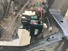
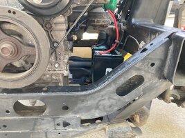
I went with the G30. It is the next step down from the 34 series and it fits in a secure nest on the drivers side frame where I needed it to.
IMG_0498.jpg
To help the battery recover after starts, I purchased one of their 6 amp chargers. I'll recharge the battery as needed and push the car (vs making multiple starts) along in the staging lanes.
The battery is secured and wired in place. The size and position of the battery, and the routing of the cables leaves me a generous channel to route the engine cooling inlet/outlet hoses through back to where I'll mount the radiator.
IMG_0499.jpg
I made good progress this weekend. I fitted some rear brake rotors and bled the brakes. The brake pedal is solid and was fabricated with provisions for setting the application height. It's a huge relief to find that the brake system is good for initial road testing.
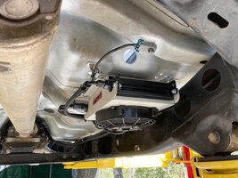
I have filled the differential and transmission, and have pre-wired the trans cooler with a temp sensor and switched over-ride:
IMG_0502.jpg
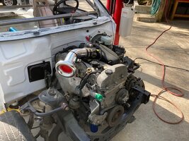
This weeks goal is to get the truck starting and running so that it moves under it's own power on and off the hoist. The wiring needed to realize that is all inside the cabin, and while there is sufficient space, I find it difficult to make this old body bend and conform into the required positions for any length of time. Here is a final image of the work in progress. I'm new to the south, but I'm told the pine pollen that covers everything down here will be ending shortly.
IMG_0500.jpg Cheers fellas,
Rick
 
Last edited:

rchalmers3

Original poster
Member
Jul 11, 2020
207
Irmo, SC
9 April 2022 update:

Fellas, I'm riding the struggle bus and can't get the conductor to pull over. I'm seeking your experience and advise.

The engine starts and runs for a few seconds, then shuts off. It does not accept throttle from the pedal and has a P2138 code that is present at key up. That's the Accelerator Pedal Position (APP) sensor 1-2 correlation code.
I have read over the diagnostic manual and checked the relevant circuit wires for proper placement in the C1 connector, and have confirmed all wires are not shorted. Each wire has acceptable resistance of .4 ohms. Further, the 5v reference and respective low reference source for each of the two sensors are present.

The description in the diagnosis of the circuit states the two sensors are supposed to produce opposite signals: sensor 1 near low reference at idle, and sensor 2 near 5v reference at idle. My two pedal assemblies (PN 15145758) do not act that way! Both sensors are near hi ref at idle!

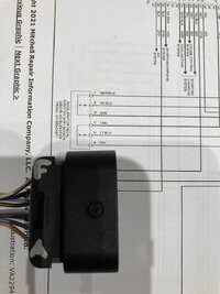
If I were to reverse the positions of 5v and lo ref to sensor 1, I believe the APP would provide a signal to the ECM that matches the description in the FSM. And here is an interesting corroborative detail: The drawing and pin call out to APP sensor in the FSM appears incorrect. The hi and lo ref signal wires appear switched! Here is a photo that hopefully demonstrates the issue. The sensor 1 tan and purple wires in the connector are the 5v ref and low ref wires, and they are in switched positions relative to the FSM:
IMG_0510.jpg
Because I am not starting with a vehicle that was once a whole, operational vehicle, and because I'm dealing with a bunch of thrown together parts, and because I'm lacking experience, I need to hear from you before I swap the hi and low reference pins in the APP sensor 1 connector.

Edit: sorry for the crappy photo.

Thanks fellas,
Rick
 

rchalmers3

Original poster
Member
Jul 11, 2020
207
Irmo, SC
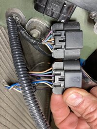
Looky here fellas, the wire placement in the APP sensor connector on my test platform (top connector) has the tan and purple wires swapped, and I know it works!
I wanna hear the truck run, so I'll do the deed and make the change to the drag car harness connector. But I really would like to know why? Did the engineers change the APP strategy at some point in time? I have a pile of wiring harnesses and pedals to draw from, even though the gas pedal PN seems to carry through the year range. I'd still like to hear from you.
IMG_0512.jpg
 

flyboy2610

Member
Aug 24, 2021
467
Lincoln, Ne.
Just throwing something out there:
The 5V reference signal is shared by the fan clutch as well. The fan clutch is a known trouble maker (kind of like me in grade school, not proud of that BTW!) and can cause all kinds of grief. Check the connector plug there for broken or chafed wires, loose connections, etc. If all looks good, unplug the fan clutch completely and see if the problem goes away. If it does, replace the fan clutch with a good high quality replacement.
My apologies if this has already been covered.
 
  • Like
Reactions: rchalmers3

rchalmers3

Original poster
Member
Jul 11, 2020
207
Irmo, SC
My project car starts, runs and stops. I filled enough transmission fluid in the trans to make the internals apply. I have realized my goal of assembling a vehicle that can be moved in and out of the work space under it's own power. It has no cooling system, so I won't be testing it around the block for awhile.

I'm gonna crack open a beer and savor the moment. I'll reflect on the APP mystery and wait for the guru's of this forum to chime in and explain why there are differences in the APP wiring.

Cheers to all,
Rick
 
  • Like
Reactions: FloMaxSS

flyboy2610

Member
Aug 24, 2021
467
Lincoln, Ne.
If there's no cooling system there's no fan clutch. No fan clutch, no 5V reference signal. This could be the source of the 5V reference issue.
 
  • Like
Reactions: rchalmers3

Forum Statistics

Threads
23,330
Posts
637,991
Members
18,534
Latest member
06_4.2_4x4_ls

Members Online