Cool build you have going Rick! I have a couple V8 SS's but, like you, I intend on building up some 4200 trailblazers. Lots of potential in this engine.. lighter and better F/R weight distribution than even an LS. Did you know the TBSS was originally going to be a twin-turbo 4200 w AWD? That's a set-up I want to replicate albeit with a single turbo. I'm big on the weight reduction for these platforms as well.. some of your posts gave me new ideas to decrease weight... we could probably share a lot of tips and tricks on that. I'm also very interested in your manual brakes and steering. What parts did you use for manual brakes conversion? Have you tested this brake set-up in this platform yet?
You are using an out of date browser. It may not display this or other websites correctly.
You should upgrade or use an alternative browser.
You should upgrade or use an alternative browser.
Drag racing the GMT360 with the LL8
- Thread starter rchalmers3
- Start date

Hiya @FloMaxSS, and welcome! I have not made much progress with the car, as I have been doing house remodeling work this spring into summer. I'll recap the items you have requested, but please forgive the surface rust appearing all over the previous clean metal parts. It's been awhile!I'm also very interested in your manual brakes and steering. What parts did you use for manual brakes conversion? Have you tested this brake set-up in this platform yet?
I used almost no new parts to convert the manual brakes, just one of those valves that allows for an adjustment of the rear brake pressure in relation to the front. I deleted the ABS, and used a simple brake line union in conjunction with the high quality stock brake line material to complete the rear brake circuit.

I poked around a bit and referenced existing wisdom found on the web for the booster delete. By relocating the MC pin in the brake pedal arm to create a 6:1 ratio, then relocating the MC to align with the new, (higher) pin location, I understand that the required force to slow the car can be achieved, albeit with somewhat greater pedal effort.

I disassembled the steering gear to learn how the internals worked in order to provide power assist. The assembly does not have any internal parts that could cause a safety issue, so I fitted a vent line (it's a repurposed axle vent) connecting the pressure and drain ports. I left some oil in the gear for lubrication.

I will let you know the results of these mods someday. With the vehicle weight reduction I'm achieving, I expect the brakes will work as expected. The pedal effort and stroke should be acceptable, at least to serve as a starting point for further mods or another MC selection. Removing weight should also lighten the steering effort, but I'm less worried about that.
Cheers, Rick
One thing I have accomplished on this project is the purchase and installation of a tool that will allow this old man be productive with less time on the ground.


Since the above photo, I now have the larger G86 diff with 4:11 gears fitted. I replaced the rear springs with 8" sections of 3" PVC schedule 40. It just looked too goofy , sitting way up with no weight on it. I'll also replace the front springs and set the body back on the frame so that I can estimate the needed final spring loaded height.
I hope to be winding down house projects and get back to the car in a few more weeks. Thanks to all for the encouragement and interest.
4 July 2021 Update:

Hiya folks, I hope your weekend is being spent in an enjoyable manner. I spent a few days this week on the car body. I'm happy to report that I have begun adding to the project vs trying to take things away!

The cabin interior has received as much material removal as I'm willing to do. I/m left with figuring out how to plug a gazillion (ok, a million) holes from 1/8" to 5/8" in diameter in order to seal the cabin from the potential intrusion of smoke and flame.
I can cut out a bit more of the body exterior, as I'm considering doing a complete shave of the cowl, forgoing the wipers, and to excise those "heavy diaper" looking appendages that hang down behind the rear wheels. You can see those baggy looking things in the previous photo of the body on the hoist. But more on those details later.

I have begun the fitment of an 8 point cage. This view is of the driver side B pillar, looking in from the rear door opening. These B pillar pedestals are made of 1/8" plate steel and will serve as the base for the main roll cage hoop.
I measured up and bought a custom cage from rhodesracecars.com. The kit cost $600 delivered, and while it would have been nice to receive a bit more customization to match the cars roof and A pillar curves, I am certain I could not have bought a tube bender and material for that amount. I'll share more photos of the cage fitment.

I intend to drape mold plexiglass sheets over the OEM safety glass for a replacement windshield and back glass. This requires being able to heat an enclosure of sufficient size to 325*(f). I sourced a free electric stove and modified it to blow the heated air up into a box that I assembled from salvaged wood. The only cost thus far was for the foil lined Rockwool insulation panels and hi-temp aluminum foil tape. Hope it works....
I am able to fit the pedestals and tack weld the roll cage using a MIG welder with acceptable results in the outdoors, baring too much breeze blowing away the shielding gas. I have purchased a TIG welder for performing final welding on the cage, and for the aluminum pieces I anticipate for much of the build. I realize need a lot more time with the TIG welder in order to attain consistent, acceptable results. For now, I am enjoying the challenges and progress of this senseless project!
Thanks to all for your comments, encouragement and suggestions.
Rick
Hiya folks, I hope your weekend is being spent in an enjoyable manner. I spent a few days this week on the car body. I'm happy to report that I have begun adding to the project vs trying to take things away!
The cabin interior has received as much material removal as I'm willing to do. I/m left with figuring out how to plug a gazillion (ok, a million) holes from 1/8" to 5/8" in diameter in order to seal the cabin from the potential intrusion of smoke and flame.
I can cut out a bit more of the body exterior, as I'm considering doing a complete shave of the cowl, forgoing the wipers, and to excise those "heavy diaper" looking appendages that hang down behind the rear wheels. You can see those baggy looking things in the previous photo of the body on the hoist. But more on those details later.
I have begun the fitment of an 8 point cage. This view is of the driver side B pillar, looking in from the rear door opening. These B pillar pedestals are made of 1/8" plate steel and will serve as the base for the main roll cage hoop.
I measured up and bought a custom cage from rhodesracecars.com. The kit cost $600 delivered, and while it would have been nice to receive a bit more customization to match the cars roof and A pillar curves, I am certain I could not have bought a tube bender and material for that amount. I'll share more photos of the cage fitment.
I intend to drape mold plexiglass sheets over the OEM safety glass for a replacement windshield and back glass. This requires being able to heat an enclosure of sufficient size to 325*(f). I sourced a free electric stove and modified it to blow the heated air up into a box that I assembled from salvaged wood. The only cost thus far was for the foil lined Rockwool insulation panels and hi-temp aluminum foil tape. Hope it works....
I am able to fit the pedestals and tack weld the roll cage using a MIG welder with acceptable results in the outdoors, baring too much breeze blowing away the shielding gas. I have purchased a TIG welder for performing final welding on the cage, and for the aluminum pieces I anticipate for much of the build. I realize need a lot more time with the TIG welder in order to attain consistent, acceptable results. For now, I am enjoying the challenges and progress of this senseless project!
Thanks to all for your comments, encouragement and suggestions.
Rick
WOW... Now THAT is what I call a GMT-360 DIET... But Every Little Bit Counts when the XMAS Tree Goes Green and the Scale is Lighter.
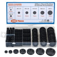
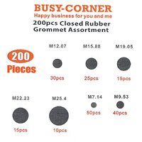
As for finding the Right Atmospheric Body Panel Sealing Plugs... Have a Look-See over at THESE on Amazon for Sealing Rubber Grommets that will probably Fit The Bill:
Before I forget to cover this Important Subject...
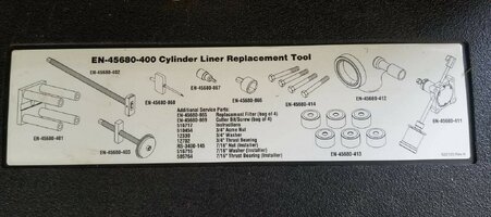
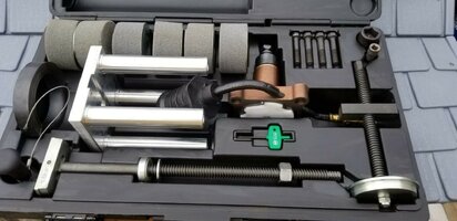
Once you begin Racing... Circumstances may prevail that involve Damage to the Cylinder Walls of the LL8 Engines you build. The Chilled Cast Iron Cylinder Sleeves installed into the GM Atlas 4.2L LL8 Engine Blocks are only 1.5mm Thick and so the options for Machining defects out of them narrows quite dramatically. However, there IS a remarkably simple and relatively easy way to perform these repairs... by completely replacing them with Melling Cylinder Sleeves Part # CSL331F sold by RockAuto for $30.00 per Cylinder and which have been designed specifically for the 4,5 & 6 Cylinder Atlas Motors using the K&M EN-45680-400 Tool Kit to remove any damaged ones and then install the New Cylinders renewing the Engine Block back to a "Factory Fresh" Condition.
I can report to you and @JayArr that there are no less than Three Complete Kent-Moore Cylinder Replacement Tool Kits available as of this very Posting over on eBay via this Link for around $300.00 (Which is an Absolute STEAL...) So my suggestion though would be ...Offer the eBay Vendor $275.00 while the chances still exist to obtain this rare tool kit. 'Better to Have It and NOT Need It...' and so forth.

Please visit THIS Thread around Post #s 132-134 & 137 then 140-149 where I have covered all of the fine grain details (With OEM Instructional Images and some Videos) about what this Tool Kit Does... and How to Use it properly. Pay particular attention to the use of a 400 Grit Ball Hone to prepare the New Cylinders with a Plateau Hone for using Moly-Coated Factory Compression Rings and assist with Breaking them in correctly:
 gmtnation.com
As for finding the Right Atmospheric Body Panel Sealing Plugs... Have a Look-See over at THESE on Amazon for Sealing Rubber Grommets that will probably Fit The Bill:
Amazon.com: 200 Pieces Closed Rubber Grommet Firewall Solid Closed Hole Plug Assortment Kit for Wire Electrical Appliance Plumbing(BUSY-CORNER) : Industrial & Scientific
Buy 200 Pieces Closed Rubber Grommet Firewall Solid Closed Hole Plug Assortment Kit for Wire Electrical Appliance Plumbing(BUSY-CORNER): Grommet Kits - Amazon.com ✓ FREE DELIVERY possible on eligible purchases
www.amazon.com
Before I forget to cover this Important Subject...
Once you begin Racing... Circumstances may prevail that involve Damage to the Cylinder Walls of the LL8 Engines you build. The Chilled Cast Iron Cylinder Sleeves installed into the GM Atlas 4.2L LL8 Engine Blocks are only 1.5mm Thick and so the options for Machining defects out of them narrows quite dramatically. However, there IS a remarkably simple and relatively easy way to perform these repairs... by completely replacing them with Melling Cylinder Sleeves Part # CSL331F sold by RockAuto for $30.00 per Cylinder and which have been designed specifically for the 4,5 & 6 Cylinder Atlas Motors using the K&M EN-45680-400 Tool Kit to remove any damaged ones and then install the New Cylinders renewing the Engine Block back to a "Factory Fresh" Condition.
I can report to you and @JayArr that there are no less than Three Complete Kent-Moore Cylinder Replacement Tool Kits available as of this very Posting over on eBay via this Link for around $300.00 (Which is an Absolute STEAL...) So my suggestion though would be ...Offer the eBay Vendor $275.00 while the chances still exist to obtain this rare tool kit. 'Better to Have It and NOT Need It...' and so forth.
GM Kent Moore En-45680-400 Cylinder Liner Repair Kit for sale online | eBay
Find many great new & used options and get the best deals for GM Kent Moore En-45680-400 Cylinder Liner Repair Kit at the best online prices at eBay! Free shipping for many products!
www.ebay.com
Please visit THIS Thread around Post #s 132-134 & 137 then 140-149 where I have covered all of the fine grain details (With OEM Instructional Images and some Videos) about what this Tool Kit Does... and How to Use it properly. Pay particular attention to the use of a 400 Grit Ball Hone to prepare the New Cylinders with a Plateau Hone for using Moly-Coated Factory Compression Rings and assist with Breaking them in correctly:
ENGINE SWAP: 2004 for 2002 GM ATLAS 4.2L MOTOR
Well… After waiting damned near a full month… The 95 MM Flex-Hone Tool has arrived… and it seems a good time to mention that if you get this deep inside of your engine and after looking over all of the cylinders in your engine… you decide to do it the justice necessary by performing the Hone Out...
Attachments
Last edited:
As for finding the Right Atmospheric Body Panel Sealing Plugs... Have a Look-See over at THESE on Amazon for Sealing Rubber Grommets that will probably Fit The Bill:
Once you begin Racing... Circumstances may prevail that involve Damage to the Cylinder Walls of the LL8 Engines you build.... there IS a remarkably simple and relatively easy way to perform these repairs... by completely replacing them with Melling Cylinder Sleeves Part # CSL331F
Cheers 2MRRSM, I considered using those as a simple solution. I have a sundry selection of plastic plugs that I have mined from various projects over the past decades, however I'm not sure a plastic plug is a suitable blocking material for a flame.... I'll have to do a bit more poking around the interwebs I guess, in order to satisfy my apprehensions.
My experience over the past couple of years in sourcing these engines at a good price can be summed up simply, and here it is: there are two types of the Atlas 4200, those that run and those with ventilated blocks. Thus far, I have found three running engines in a reasonable price range (>$600), and they have all measured up for standard pistons and rings. THE REST of the engines had seized or had a hole punched in the #1 and #2 cylinder block area by the time I come across them in the boneyard on on Facebook Market Place. Therefore I thank you for reminding me of the potential for performing a re-sleeve of the block, but no amount of re-sleeving is gonna fix that!
Cheers,
Rick
Last edited:
Tankcruiser
Member
ventilated blocks? didnt know that... what is it? im curious.....
Hiya Tankcruiser,ventilated blocks? didnt know that... what is it? im curious.....
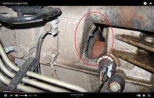
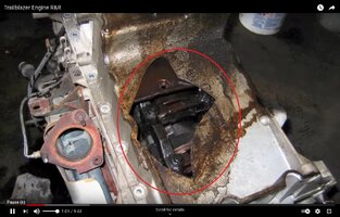
A ventilated block is just that: an engine block where the ordinarily closed PCV system has received an (unwanted!) opening to atmosphere.
Here is a ventilated block I kept and use for general mock-up and fitment, and was the receipient of my first alloy welding attempts:

You can see the ventilation hole above and behind the oil filter flange.

Any questions?!
Cheers to all,
Rick
Tankcruiser
Member
 🙂
🙂25 July 2021 update:
My first attempt at firing the drape molding oven has proven the need for more heat. It almost gets to the plastic softening point, but after 6 hours at max temp and was still 40 degrees shy of target. I need a way to operate the oven in a manner that it is not designed to do: power both the bake and broil heating elements simultaneously. The bake element operates on about a 70% duty cycle, even at the commanded max temp (550*f). I am concerned that wiring the two elements in parallel on one control will damage or overload the circuitry. If you have any suggestions or knowledge of these oven circuit control boards and strategies, please chime in.
I also will take measures to ventilate the removable top of the box, in order to allow moisture to escape. I understand the polycarbonate will fog and be ruined if not pre-dryed for several hours at low temp before heating it up for molding. I'll also add a small fan to augment the convection process. I'll let you know the results as they come.
I have the basic 4 points of the 8 point roll cage assembled and tacked in place.

I need some fancy bits and materials for supporting the steering column. I'll order those this week.

I'm enjoying the utility of the TIG welder, especially since my MIG welder has failed. The motor inside the MIG machine that feeds the wire has lost the torque needed operate smoothly and consistently. Fortunately the company was gracious and has sent me a complete replacement welder.
I had to section the A pillar bars. It seems I'm a complete beginner at getting the coping right, and had to resort to fitting the upper cope individually.
The steering wheel is mocked in the fully lowered position. The next task is to obtain a harness seat and fabricate a seat mounting system. I'll place the seat as low as possible while complementing the steering wheel and pedals.
Cheers to all,
Rick
My first attempt at firing the drape molding oven has proven the need for more heat. It almost gets to the plastic softening point, but after 6 hours at max temp and was still 40 degrees shy of target. I need a way to operate the oven in a manner that it is not designed to do: power both the bake and broil heating elements simultaneously. The bake element operates on about a 70% duty cycle, even at the commanded max temp (550*f). I am concerned that wiring the two elements in parallel on one control will damage or overload the circuitry. If you have any suggestions or knowledge of these oven circuit control boards and strategies, please chime in.
I also will take measures to ventilate the removable top of the box, in order to allow moisture to escape. I understand the polycarbonate will fog and be ruined if not pre-dryed for several hours at low temp before heating it up for molding. I'll also add a small fan to augment the convection process. I'll let you know the results as they come.
I have the basic 4 points of the 8 point roll cage assembled and tacked in place.
I need some fancy bits and materials for supporting the steering column. I'll order those this week.
I'm enjoying the utility of the TIG welder, especially since my MIG welder has failed. The motor inside the MIG machine that feeds the wire has lost the torque needed operate smoothly and consistently. Fortunately the company was gracious and has sent me a complete replacement welder.
I had to section the A pillar bars. It seems I'm a complete beginner at getting the coping right, and had to resort to fitting the upper cope individually.
The steering wheel is mocked in the fully lowered position. The next task is to obtain a harness seat and fabricate a seat mounting system. I'll place the seat as low as possible while complementing the steering wheel and pedals.
Cheers to all,
Rick
Another detail: I replaced the front suspension upper A arms:
These arms provide about 1.5* of camber correction at the current height.

It's still about 1* negative at the current height, but I have not touched the lower arm pinch adjusters. This was a modification that was not too expensive, and with the front end off, it only took about 5 minutes to fit each side.
These arms provide about 1.5* of camber correction at the current height.
It's still about 1* negative at the current height, but I have not touched the lower arm pinch adjusters. This was a modification that was not too expensive, and with the front end off, it only took about 5 minutes to fit each side.
Are you intent on switching to lighter (smaller?) Rims and Tires on the Front? a little more Rake can't hurt with a lot less weight to "Drag" along during the "Races"... :>)
Yes, however, this is a non-budgeted project. My wife has figured this out and has thrown me various house remodel projects that are also non-budgeted, in a challenge to my cash grab. I have decided that it is best to accept her projects in order to keep the peace and to share any surplus income available. I figure that eventually she will run out of projects and I'll be basking in race car funds....Are you intent on switching to lighter (smaller?) Rims and Tires on the Front? a little more Rake can't hurt with a lot less weight to "Drag" along during the "Races"... :>)
Rims and tires much later!
Cheers,
Rick
Mooseman
Moderator
Hahahaha! You're funny. That will never happen! But smart man for keeping the peace.I figure that eventually she will run out of projects and I'll be basking in race car funds....
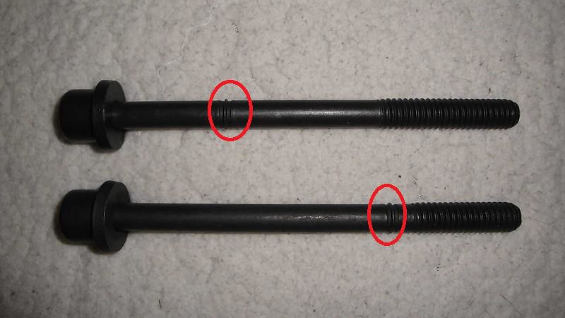
Hey folks. I have two requests for assistance from you GM Atlas 4200 experts and part number numerologists: What is the part number for the early (m10x1.5) crankshaft flex plate bolts?
I am fitting a fully counter weighted 2005 crank into a later model engine. The later bolts are m10x1.0. I have numerous late engine bolts and will award bonus points for those of you who have a stash of the early bolts and are willing to trade 8 of them for multiple sets of the later ones.
I have a second request for assistance: How do the late model rods with the squirt hole fit the crank? Are they intended to spray oil on the bottom of the piston before TDC, or after??? Any verifiable proof of fitment is appreciated.


I bought 6 rebuilt 2008 rods in order to complete this mongrel motor and the rods no longer have the number and orientation marks on the caps. While my guess is that the oil should coat the bottom of the piston before combustion, I'm not an engineer nor did I ever play one on TV, and I appeal to you sage soothsayers!
This engine build is engine version 2.0. My goal is to make the best combination of a stock short block breath to the best of it's ability. It will be fitted with a 9000 RPM crankshaft harmonic racing dampener and a very expensive head that has received porting and valves and a cut for increased compression.
Cheers to all,
Rick
I am fitting a fully counter weighted 2005 crank into a later model engine. The later bolts are m10x1.0. I have numerous late engine bolts and will award bonus points for those of you who have a stash of the early bolts and are willing to trade 8 of them for multiple sets of the later ones.
I have a second request for assistance: How do the late model rods with the squirt hole fit the crank? Are they intended to spray oil on the bottom of the piston before TDC, or after??? Any verifiable proof of fitment is appreciated.
I bought 6 rebuilt 2008 rods in order to complete this mongrel motor and the rods no longer have the number and orientation marks on the caps. While my guess is that the oil should coat the bottom of the piston before combustion, I'm not an engineer nor did I ever play one on TV, and I appeal to you sage soothsayers!
This engine build is engine version 2.0. My goal is to make the best combination of a stock short block breath to the best of it's ability. It will be fitted with a 9000 RPM crankshaft harmonic racing dampener and a very expensive head that has received porting and valves and a cut for increased compression.
Cheers to all,
Rick
Last edited:
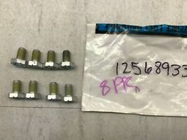
These should work...
GM Part# 12568933
On Sale NOW BNIB (Brand New In Box) on eBay via THIS Link:

...and for the REST of the Need-2-Know-About Vortec 4200 Engine Fasteners, I parked images of them all that includes the packing and GM or ACDelco Part Numbers HERE:
 www.flickr.com
And give THESE Guys a Call about the Rod Specs & Lubrication issues:
GM Part# 12568933
On Sale NOW BNIB (Brand New In Box) on eBay via THIS Link:
8 Pack GM Trailblazer Envoy 4.2L OEM Transmission Flex Plate Bolt GM 12568933 | eBay
FREE Trial! No Labor Warranty. · We strive to earn 100% perfect "FIVE-STAR" scores from you.
www.ebay.com
...and for the REST of the Need-2-Know-About Vortec 4200 Engine Fasteners, I parked images of them all that includes the packing and GM or ACDelco Part Numbers HERE:
GM ATLAS 4.2L ENGINE FASTENERS
These Images include the Major TTY Engines Fasteners and Gasket Sets for the GM Atlas 4.2L In Line Six Cylinder Engine.
www.flickr.com
And give THESE Guys a Call about the Rod Specs & Lubrication issues:
Vortec 4200 Connecting Rods | 4.2 Inline 6 Rods
Vortec 4200 connecting rods. Molnar Technologies extremely strong GM Chevy 4.2 Vortec DOHC connecting rods for stock, high performance and racing engines.
molnarrods.com
Attachments
Last edited:
I dunno, those look like m10x1.0 I already have a nice collection of those. But the year range covers the entirety of the 7x cranks, so, ???
The Rockauto 2005 crank is drilled and tapped for m10x1.5. I'd like to investigate this further... could they have made a mistake?
Anyone able to add some understanding to this issue? Are their more than one part numbers for the flexplate bolts?
EDIT: Perhaps this crank is tapped to the LS bolt size of m11x1.5 I'll have to re-measure the crank to confirm..... If so, there are inexpensive solutions on Ebay.
Rick
Last edited:
You can also look up those Bolt Specs for Flex Plates at the ARP Site as they always have ASE and Metric High Quality Fasteners that can be chosen for the correct Strength, Metric Size, Thread Count, Thread Pitch and Bolt Length to suit this unique situation:
 arp-bolts.com
ARP | The Official Web Site
Rick... Some of THIS information may prove very helpful in your present situation:
An Android APP for Accurately Measuring Fasteners and Threaded Holes:

 play.google.com
gmtnation.com
An Android APP for Accurately Measuring Fasteners and Threaded Holes:
Thread pitch gauge - Apps on Google Play
Find the specifications of thread pitch for screws, nuts, bolts and pipes.
The Most Accurate On-Line Ruler...
We've all been here... Holding either a Part...a Piece of Metal or a Bolt and wondered..."How Large... or Small...How Thick or Thin IS this Thing... Really?" and NOT had the means at hand to make an Accurate Measurement. Well... Bookmark and also Download THIS Page for a "Ready Ruler" that is...
Last edited:
Since there is a general "Dearth of Data" about which way to properly orient and install the 2006 & < Connecting Rods to Pistons for the proper Piston and Cylinder Wall Lubrication, if you check out what Calvin is talking about at around 8:18 and onward into this Video, he clarifies the many differences between the Old Con-Rods and the Newer Versions that sports the Oiler Boss located only on a Single Side of the Rod. It's tantalizing that he begins to explain, but unfortunately, he stopped short of providing more precise installation instructions,
Perhaps you can contact or message him via his YouTube Project Links here below and get the Straight Scoop on this subject. My belief is that whichever side is the area where the Pistons suffer the Greatest 'Piston to Cylinder Wall Thrust Pressure' while Rotating Clockwise ...THAT would probably be where the Oil should be getting Squirted to do the Engine the Most Good while fighting against the dominant friction being created.
But... Let's hope that Calvin knows for certain and will advise you about it... :>)
FYI, the rod oil ports are oriented on the exhaust side, according to the manual. I would gladly post the portion of the manual covering this detail, however Mitchell DIY does not allow reprinting text out of their manual subscription service.
This orientation was my assumption, given the purpose is to squirt oil under the piston, thus providing a method of combustion heat transfer out of the piston material.
I apologize for not consulting the manual before posting, and I thank those of you who chose to remain silent, allowing me to find my own way!
Rick
I acknowledge these posts are "stream of conscious", but I still gotta ask:
Does anyone have a stock motor with the head off, or an image of one that clearly shows the locations of the valve reliefs on the pistons?
The manual indicates the valve recesses are for the intake side, which makes sense because the intake valves are larger. However there are triangles on the piston tops, which if one ASSUMES to be pointers indicating the front of the engine, would place the valve reliefs on the exhaust side.
Here is what I mean:

Thanks in advance,
Rick
Does anyone have a stock motor with the head off, or an image of one that clearly shows the locations of the valve reliefs on the pistons?
The manual indicates the valve recesses are for the intake side, which makes sense because the intake valves are larger. However there are triangles on the piston tops, which if one ASSUMES to be pointers indicating the front of the engine, would place the valve reliefs on the exhaust side.
Here is what I mean:
Thanks in advance,
Rick
In the Old Days... We used "Engine Builder's Modeling Clay" to inspect Compression Quench and Piston to Valve Relief Clearances when Experimenting with Piston and Rod Combos:
Engine Build "CLAY" Mock Up Procedures for the GM Atlas Vortec 4200 Engines:
(1) Mount the Engine Block on the Engine Stand.
(2) Install the Crankshaft using Fresh Main Bearings @ the 1, 5 & 7 Mains (only 15 Ft Lbs).
(3) Install ONE "Test Piston" with Rings & Con-Rod in the #1 Cylinder (only 10 Ft Lbs).
(4) Position the "Test Piston" in Mid-Cylinder with Builder's Clay filling the Valve Reliefs.
(5) Invert the Engine Block & Rotate the #1 Cylinder "Test Piston" to just below TDC.
(6) Lay the MLS Gasket and the Engine Head onto the Block. DO NOT BOLT IT DOWN.
(7) CAREFULLY Rotate the Intake Camshaft Clockwise until LIGHT Contact is made.
(8) CAREFULLY Rotate the Exhaust Camshaft Clockwise until LIGHT contact is made.
(9) Lift Off the Engine Head and Examine the Combustion Chamber and #1 "Test Piston".
(10) CAREFULLY Use the Hex Flats on each Camshaft to affect these Clockwise Rotations.
(11) If the First Test Results clearly show the Valves to Piston Relief Contacts... DONE.
(12) If NOT... Reverse the Piston to Rod Position and Repeat Steps 3-10. Examine Results.
NOTE:
The "Arrow" space that has been Machined Out is probably for a Spark Plug Electrode Relief, so make sure to have one Installed in the #1 Cylinder Head position and examine the Piston Head for its presence and location in the Clay Markings.
Just a suggestion... But this Method WILL glean definitive proof as only ONE of these can be Right.
Last edited:
DUDE! I was just looking through your photo albums in search of an image that would guide me. I need to get the short block together to measure the piston height. The head is at the head porting specialist and they need to know how far up the pistons rise above deck height.
The shop has my spare head as well, so I gotta figure this out without borrowing some clay from my daughter...
Thanks,
Rick
The shop has my spare head as well, so I gotta figure this out without borrowing some clay from my daughter...
Thanks,
Rick
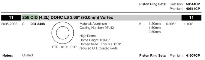
Update: I contacted Mahle for information on the piston orientation, and they said they made those OEM pistons but they suggest I follow the manufacturers directions, regardless of what I believe to be directional arrows.... So I have assembled the pistons as per the FSM. Here is a screen grab that is one of three images that displays the orientation. You will have to look closely to see the valve relief details on the piston top:

The aftermarket Mahle piston that has the correct specs and reliefs for the valves is found here on Summit: https://www.summitracing.com/parts/mah-s2243885 However the Mahle product number is slightly different: 2443885wr.
I have opened up the ring gaps and fitted the rings on the pistons. My next hurdle is returning the rod bearings that were supplied. There are no holes in the upper shell for the oil squirt feature. Progress is being made, but slowly and in fits and starts.
Meanwhile, I scored a low mileage Gen IV LS motor. It's an iron block 5.3 with 799 heads. It needs repairs, but I can see to that and am going to put it into stasis for a future project.
Rick
Rick
Rick
The aftermarket Mahle piston that has the correct specs and reliefs for the valves is found here on Summit: https://www.summitracing.com/parts/mah-s2243885 However the Mahle product number is slightly different: 2443885wr.
I have opened up the ring gaps and fitted the rings on the pistons. My next hurdle is returning the rod bearings that were supplied. There are no holes in the upper shell for the oil squirt feature. Progress is being made, but slowly and in fits and starts.
Meanwhile, I scored a low mileage Gen IV LS motor. It's an iron block 5.3 with 799 heads. It needs repairs, but I can see to that and am going to put it into stasis for a future project.
Rick
Thank you. I'll take the time to employ the clay measures after assembling the short block, but before squeezing the head down onto the new gasket. This engine assembly has generated greater cost over a stock rebuild and deserves a little insurance.In the Old Days... We used....
(1) Mount the Engine Block on the Engine Stand.
(2) Install the Crankshaft using Fresh Main Bearings @ the 1, 5 & 7 Mains (only 15 Ft Lbs).
(3) Install ONE "Test Piston" with Rings & Con-Rod in the #1 Cylinder (only 10 Ft Lbs).
(4) Position the "Test Piston" in Mid-Cylinder with Builder's Clay filling the Valve Reliefs.
(5) Invert the Engine Block & Rotate the #1 Cylinder "Test Piston" to just below TDC.
(6) Lay the MLS Gasket and the Engine Head onto the Block. DO NOT BOLT IT DOWN.
(7) CAREFULLY Rotate the Intake Camshaft Clockwise until LIGHT Contact is made.
(8) CAREFULLY Rotate the Exhaust Camshaft Clockwise until LIGHT contact is made.
(9) Lift Off the Engine Head and Examine the Combustion Chamber and #1 "Test Piston".
(10) CAREFULLY Use the Hex Flats on each Camshaft to affect these Clockwise Rotations.
(11) If the First Test Results clearly show the Valves to Piston Relief Contacts... DONE.
(12) If NOT... Reverse the Piston to Rod Position and Repeat Steps 1-10. Examine Results.
NOTE:
The "Arrow" space that has been Machined Out is probably for a Spark Plug Electrode Relief, so make sure to have one Installed in the #1 Cylinder Head position and examine the Piston Head for its presence and location in the Clay Markings.
Rick
Rick
I'd say you have Definitive Proof that the Piston Valve Relief Cut-Outs on Late Model 4.2L Engines are meant for the Larger Intake Valves and thus, they must be oriented towards the Driver's Side of the LL8 Block when facing the Front of the SUV during Engine Assembly. If it's Okay with you ... I've captured a 'closer up' image from the one you've attached to make the viewing of this set - up a Little Bit EZR to See:
I like your Mind Set... Because paying attention to the "Devil In The Details" like this NOW means that YOU will likely end up with getting "Lane Choice... and First Place" when the Smoke Clears and the Race Performance Tickets get handed out... :>)
"You Can't Make the Scene... If You Ain't got The Green..." Jim Carrey as "The Mask"
Attachments
Last edited:
October update: What's that saying about life being comprised of what you do vs what you want to do?
I haven't worked a bit on the car, however I have gathered the expensive bits for building a stronger 4L60E transmission, and I have engine ver 2.0 assembled. The tranny bits are just a big box of Sonnax boxes, so here is an image of something assembled!

This is a mongrel assembly: a fully counter weighted 7x crank with 2006 pistons and rods, and a 2008 head ported with larger exhaust valves and seats.

Along with the head work and larger valves I installed heavier springs. The cams are stock, however I fitted a custom dampner with the intention of revving the engine to 8000 rpm.
It may be another year, but when the time comes to run this engine, I'll pre-oil it properly this time.
I have ordered a steel exhaust flange and T4 turbo flange. I have never made go fast bits, so my first attempt will be to weld up a simple log manifold. This mock up block and head will serve as a fitting and assembly fixture for the manifold construction. I'll be very satisfied if I'm able to produce a workable piece.
Looking forward at my calendar, the neighbors want me to remodel their main bathroom shower and floor. I accepted the job, as the income will cover most of the expensive work that was done to the head.
I acknowledge this project is the opposite of those flashy 15 minute YouTube shows, and more akin to watching glaciers melt... drip, drip drip. Meanwhile, I'll thank you for your continued interest!
Rick
I haven't worked a bit on the car, however I have gathered the expensive bits for building a stronger 4L60E transmission, and I have engine ver 2.0 assembled. The tranny bits are just a big box of Sonnax boxes, so here is an image of something assembled!
This is a mongrel assembly: a fully counter weighted 7x crank with 2006 pistons and rods, and a 2008 head ported with larger exhaust valves and seats.
Along with the head work and larger valves I installed heavier springs. The cams are stock, however I fitted a custom dampner with the intention of revving the engine to 8000 rpm.
It may be another year, but when the time comes to run this engine, I'll pre-oil it properly this time.
I have ordered a steel exhaust flange and T4 turbo flange. I have never made go fast bits, so my first attempt will be to weld up a simple log manifold. This mock up block and head will serve as a fitting and assembly fixture for the manifold construction. I'll be very satisfied if I'm able to produce a workable piece.
Looking forward at my calendar, the neighbors want me to remodel their main bathroom shower and floor. I accepted the job, as the income will cover most of the expensive work that was done to the head.
I acknowledge this project is the opposite of those flashy 15 minute YouTube shows, and more akin to watching glaciers melt... drip, drip drip. Meanwhile, I'll thank you for your continued interest!
Rick
If you have not as yet come up with a Turbo-Header Design that is cast in stone, there are just a few images of the GM Vortec 4200 Motor being outfitted with Turbo-Headers available for comparison. Here is the smattering of what can be found on line. Check out the Super-Charger on that Colorado:
(NOT my images... All found via DuckDuckGo Search)


(NOT my images... All found via DuckDuckGo Search)
Be curious to know just how much HP you add from NOT having all of those Accessories, Pulleys and Idlers scavenging so much Power from the Vortec 4200... and perhaps you could take this one step further by using an Electric Water Pump, too:
OEM Serpentine & Hardware:

Versus The NEW Belt Arrangement for "The Chalmers" Race Truck Engine:

OEM Serpentine & Hardware:
Versus The NEW Belt Arrangement for "The Chalmers" Race Truck Engine:
Last edited:
More awesome work Rick! Congrats on doing the research to build a 4200 with the best compiled bits available. Can't wait to see how this engine, manual brakes and steering perform! The process is like drip,drip,drip but those of us that have done these involved builds can appreciate the patience it takes.
@FloMaxSS, I'm happy to hear there is at least one experienced builder watching over my progress. The shortcoming about posting progress reports is that you will only be able to advise me on my errors AFTER I've performed some work and posted it! I really dislike backing up my work for do-overs!
It's now November: cold winds blowing a combination of rain and fallen leaves all around and over my outdoor work space. I's time to wrap up the outdoor work, so I did the final body trimming and filled the holes in the firewall and front seat area.


The cowl is completely removed. I originally imagined retaining the wipers, for some reason. I guess I have watched too many Drag Week videos. anyway, it's now clean.

Here's how you fill multiple small or irregular shaped holes. Eastwood sells these standard diameter slugs made of body metal thickness. You drill out the hole to the slug size, and there, Bob's your uncle. For holes 3/8" or under, I used this:

That tool is a spring loaded copper backing plate with magnetic feet. You place it snugly against the underside of the hole and tack it closed. The copper plate prevents the molten puddle from falling.
I also excised those full diaper looking appendages from the rear of the body. The body work surrounding the fuel filler was heavier gauge, so the effort saved a bit more weight back there.

I'm all done carving weight off the carcass, with the exception of the front doors, which I can do indoors, out of the cold.
While it was raining the other day, I fabricated a test stand for observing and measuring fuel injectors. I have never made use of used of, nor modified injectors before, opting to replace them with new. However this project has me seeking ways to reuse existing resources, so I'll need to assure myself that the used and/or de-capped injectors I'll utilize will have been verified.

I utilized the fuel source I previously fabbed up for the engine test frame: a stock GMT360 fuel pump fitted into the lid of a 2 gallon bucket. For electrical power I tapped a Milwaukee M12 battery for energizing the injectors. The switch configuration allows me to view individual injectors for the spray pattern, or operate the main switch for running all 6 injectors for a measured time to determine delivery balance.
That's all I have for the moment. I have some final paint covering to do on the body, then I'll drop it back onto the chassis and park it under cover for the winter. I have begun fabricating pieces for mounting the steering column to the roll cage, and a seat mounting bracket, all of which are made out of aluminum. However I am held back by my inability to create satisfactory welds on this new to me material. The driver seat installation is really the next most important accomplishment, so that I can fit more roll cage pieces and begin to add other controls and systems.
Thank you in advance for your comments and suggestions,
Rick
It's now November: cold winds blowing a combination of rain and fallen leaves all around and over my outdoor work space. I's time to wrap up the outdoor work, so I did the final body trimming and filled the holes in the firewall and front seat area.
The cowl is completely removed. I originally imagined retaining the wipers, for some reason. I guess I have watched too many Drag Week videos. anyway, it's now clean.
Here's how you fill multiple small or irregular shaped holes. Eastwood sells these standard diameter slugs made of body metal thickness. You drill out the hole to the slug size, and there, Bob's your uncle. For holes 3/8" or under, I used this:
That tool is a spring loaded copper backing plate with magnetic feet. You place it snugly against the underside of the hole and tack it closed. The copper plate prevents the molten puddle from falling.
I also excised those full diaper looking appendages from the rear of the body. The body work surrounding the fuel filler was heavier gauge, so the effort saved a bit more weight back there.
I'm all done carving weight off the carcass, with the exception of the front doors, which I can do indoors, out of the cold.
While it was raining the other day, I fabricated a test stand for observing and measuring fuel injectors. I have never made use of used of, nor modified injectors before, opting to replace them with new. However this project has me seeking ways to reuse existing resources, so I'll need to assure myself that the used and/or de-capped injectors I'll utilize will have been verified.
I utilized the fuel source I previously fabbed up for the engine test frame: a stock GMT360 fuel pump fitted into the lid of a 2 gallon bucket. For electrical power I tapped a Milwaukee M12 battery for energizing the injectors. The switch configuration allows me to view individual injectors for the spray pattern, or operate the main switch for running all 6 injectors for a measured time to determine delivery balance.
That's all I have for the moment. I have some final paint covering to do on the body, then I'll drop it back onto the chassis and park it under cover for the winter. I have begun fabricating pieces for mounting the steering column to the roll cage, and a seat mounting bracket, all of which are made out of aluminum. However I am held back by my inability to create satisfactory welds on this new to me material. The driver seat installation is really the next most important accomplishment, so that I can fit more roll cage pieces and begin to add other controls and systems.
Thank you in advance for your comments and suggestions,
Rick
Versus The NEW Belt Arrangement for "The Chalmers" Race Truck Engine
Bear in mind I have no background in such things, but is there enough of a contact patch on the water pump/cooling fan pulley? I read a post from someone involved with the cooling fan clutch operation while apparently in the employ of GM and it was stated the cooling fan would require about 18 HP at 4000 rpm.
Hiya @TJBaker57,.....but is there enough of a contact patch on the water pump/cooling fan pulley?
Thank you for looking over the work I have published,. I appreciate you taking a moment to comment on items that you see.
My short answer to your query is: we will find out.
One of the manufacturers of electric pumps designed to replace mechanical water pumps for racing engines mentions an 11hp gain in converting, so your proposed 18hp draw (water pump plus a mounted fan) may be entirely accurate.
Adding to the understanding of what is required, I once upon time made a quick study of V groove belt applications. I learned that a V groove belt needs a minimum of 120* of wrap to properly transfer it's expected load. I acknowledge V groove belts are a different animal, but I kinda took that into consideration. The mods I made fall a bit short of that, and being that the contact is on the back of the belt, it does not receive benefit from the extra micro groove contact.
My application is different from most cases, in that I'll be producing max power for hopefully, less than 14 seconds, followed by a low speed drive back to the pits. I believe the racing drive cycle does not require the exact same consideration as a vehicle designed for over the road use.
Cheers,
Rick
You are going to run electric fan right? What parts have you devised for the cooling system so far? An electric water pump would be sweet too but wouldn't free-up as much hp as electric fans and would have to be remote-mounted.
Yes to electric fans. Also, I'm considering a relocation of the radiator to a position under the body on the driver side, where the air pump and fuel tank used to reside. The idea of having the engine sitting naked and alone on the frame in front of the firewall, under a tilt/removable front end would be the exact opposite of how the engine is packaged in the GMT360.You are going to run electric fan right? What parts have you devised for the cooling system so far? An electric water pump would be sweet too but wouldn't free-up as much hp as electric fans and would have to be remote-mounted.
But before any of that, I need to learn how to produce acceptable and consistent welds on aluminum. If I become able to weld aluminum with consistency, this entire project will be worth the expense.
Cheers,
Rick
December update: We enjoyed a stretch of pleasant weather and no rain. However the leaf fall was in full swing. I started each day clearing out the car and work space with the leaf blower. The leaf fall is easing and we are expecting more winter like weather in the coming weeks.
I made some aluminum pieces and finalized the racing seat fitment and steering column support.
After that I shortened the stock shifter and removed the lock out bits. Here is a stock shifter alongside the modded one.

I positioned the shifter in relation to the lowered and rearward seat position. To keep the cable out from under foot, I routed it in a clockwise coil behind and over the extension housing vs under the driver legs.
The driver controls are now all fixed in position. I gotta tell you, it's wonderful to be adding details vs doing all the removal work.
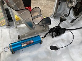
After completing the controls, I fitted an engine oil accumulator.

I added a shut off valve for the accumulator and zip tied it to the shifter bracket. I also left the traction control push button in the shifter for any possible future needs.

I'll be needing access to the area where the spare tire used to reside. I fabbed up some Home Depot plate and hinge materials with some cheap E-bay Dzus fasteners to create an access hatch.

It's gonna get colder and commence rain this week, so I am moving the project under cover. It sure is satisfying to consolidate the car body and frame, even if for a short time!
 I didn't mention it previously, but all four doors are gutted and fitted with poly-carbonate replacement glass. Each door has the lock mechanism defeated and a simple release handle fabricated.
 I'll get back to the store this week and purchase more sealant and screws for installing the quarter glass sheets. I have them patterned and cut, and it's a quick process to get them installed.
I believe I am getting close to needing the engine and transmission set in the frame, as I'll need them in place to complete the radiator and transmission cooler plumbing and to begin the wiring process.

If I get the engine and transmission in, I'll post more photos of the project. I'd like to share with you the access and exposure the engine enjoys in case you wish to do this to your Trailblazer!
Thank you all for your continued interest. I hope you are enjoying this project as much as I am.
I made some aluminum pieces and finalized the racing seat fitment and steering column support.
After that I shortened the stock shifter and removed the lock out bits. Here is a stock shifter alongside the modded one.
I positioned the shifter in relation to the lowered and rearward seat position. To keep the cable out from under foot, I routed it in a clockwise coil behind and over the extension housing vs under the driver legs.
The driver controls are now all fixed in position. I gotta tell you, it's wonderful to be adding details vs doing all the removal work.
After completing the controls, I fitted an engine oil accumulator.
I added a shut off valve for the accumulator and zip tied it to the shifter bracket. I also left the traction control push button in the shifter for any possible future needs.
I'll be needing access to the area where the spare tire used to reside. I fabbed up some Home Depot plate and hinge materials with some cheap E-bay Dzus fasteners to create an access hatch.
It's gonna get colder and commence rain this week, so I am moving the project under cover. It sure is satisfying to consolidate the car body and frame, even if for a short time!
I didn't mention it previously, but all four doors are gutted and fitted with poly-carbonate replacement glass. Each door has the lock mechanism defeated and a simple release handle fabricated. I'll get back to the store this week and purchase more sealant and screws for installing the quarter glass sheets. I have them patterned and cut, and it's a quick process to get them installed.I believe I am getting close to needing the engine and transmission set in the frame, as I'll need them in place to complete the radiator and transmission cooler plumbing and to begin the wiring process.
If I get the engine and transmission in, I'll post more photos of the project. I'd like to share with you the access and exposure the engine enjoys in case you wish to do this to your Trailblazer!
Thank you all for your continued interest. I hope you are enjoying this project as much as I am.
Attachments
Last edited:
It was a warm and foggy Saturday. I worked over a very wet floor, fitting the engine and transmission in a marine atmosphere. You can see the condensation on the polycarbonate windows.
 Here are details of the reworked wire routing from the engine back along the firewall on the driver side. The power, grounds and I/O's will pass through that blue connector into the cabin. I am pleased with the accessibility to the engine.

The passenger side is will receive the oil accumulator feed into the #5 oil galley plug (already mocked up) and a short exhaust down pipe, to be installed next.

Looks like I'll need a shorter driveshaft, after lowering the rear suspension. Shoulda seen that coming.....
Fellas, I'm planning on running a very short exhaust pipe. The end of the pipe is about 26" from the O2 sensor located in the manifold. My question is: will that be too short to avoid gas reversion, causing an incorrect reading? I'd like your thoughts.
Thank you,
Rick
Here are details of the reworked wire routing from the engine back along the firewall on the driver side. The power, grounds and I/O's will pass through that blue connector into the cabin. I am pleased with the accessibility to the engine.The passenger side is will receive the oil accumulator feed into the #5 oil galley plug (already mocked up) and a short exhaust down pipe, to be installed next.
Looks like I'll need a shorter driveshaft, after lowering the rear suspension. Shoulda seen that coming.....
Fellas, I'm planning on running a very short exhaust pipe. The end of the pipe is about 26" from the O2 sensor located in the manifold. My question is: will that be too short to avoid gas reversion, causing an incorrect reading? I'd like your thoughts.
Thank you,
Rick