- Jul 22, 2015
- 2,724
(Attention: After a 3hr drive, almost a year after installing this, I found out the harness I reference below... melted the relay plug / connectors -- which I only noticed after I almost fatally overheated the engine). Link HERE for more info... and I recommend against purchasing that particular harness. I'm ordering one from Nelson Performance as a replacement. Lesson Learned... )
So... I've been offline for a bit; maybe we'll subtitle this thread "What I did over my summer vacation"
(Note: This is going to be in at least two parts, as GMTN has a 10K character limit per post, and I know I'm > 15,000 already)
Covers:
99-06, 07 'Classic' GMT800 series
(photos show a P59 ECM; others similar)
During a P/S pump replacement, I decided to do the e-fan conversion since I was taking out so much stuff in the same area. These are found on the '05-up trucks, but can be retrofitted as far back as '99.
As for what you'll need...
A 34” core radiator (these are mostly found in 3/4-ton series – basically, anything with a 6.0L installed. They also should have the bungs for the oil cooler lines on the driver side (and you don't need to run lines to these; blockoff plugs are just fine, if you're not ready to install the oil cooler lines between the block mount location (just above the oil filter, sealed with its own blockoff plate, by default on the 5.3L and smaller V8s).
If you have a 1/2-ton 1500, your radiator has a 28” core, and you'll need to upgrade it in order for the new fan assembly to fit, as the assembly is too large, otherwise (and you'll need to be creative in mounting it. With the larger rad, it's a drop-in affair.
A fan harness with in-line relays to turn the fans on / off at the appropriate times. You can either order the GM part, or an aftermarket solution. Nelson Performance probably makes the best version, but they're expensive (triple the $ of what you find on Amazon). I went with the highly-rated Amazon solution.
The fan assembly. I went with an aftermarket from Rock that had a lifetime warranty. Note there are two versions – one has a 5- and 7-blade, the other has a 7- and 9-blade. Ostensibly, the 7&9 blade option is better, if you can find it.
Mine is the 5&7 combo.
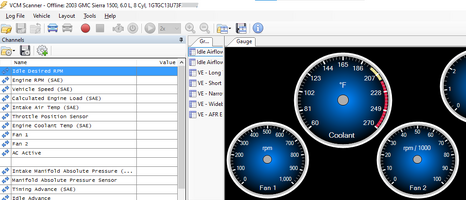
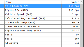
A way to program your ECM fan controls. The ability is built into the P59 ECM, but turned off on the pickups before '05, because they use the mechanical fan / clutch. It's a simple matter to turn it on with HP Tuners (I'll include a screenshot or two for reference). If you don't have HPT, resources like Limeswap and ECM 4 Less are available on a mail order basis, and whomever you have locally. Yes, I can do it for you, but you'll need to purchase license credits, as my licensure with HPT is currently on a per-truck basis. PM me for more details. But I'd go with Jeremy @ Limeswap, if you want more than the fans activated. Also, return visits for your ECM with him are only $25 (as of this writing), if you want more done later.
If you have an alternator rated at less than 130A, seriously consider upgrading it to a 130A or 145A, if possible. These fans use a lot of juice (up to 40A each), and if your alternator is rated on the small side, you may find it working harder to keep up.
To start, disco the battery, and remove the upper shroud. If you need help on how to do this, stop here, save yourself a lot of trouble, and have someone do this for you. But almost everyone here knows their way around a vehicle, so...
Remove the mechanical fan / clutch. LEAVE the serpentine belt on until you get the nut loose, as it will help hold the fan stationary. If it's been a long time (or never) since the fan / clutch retaining nut has been removed, it's going to be a bit of a struggle to get it off. But it can be done (and there are plenty of tutorials available here and elsewhere). For one that's stuck on, an air hammer with the flat chisel attachment will make quick work of the job (focus on the left side of the nut, as you're facing it.) If you don't have an air compressor, you can also get it off with a cold chisel / hand sledge, or a pipe wrench. Just make sure the pulley is immobilized, and you'll get it off. If you've had the fan / clutch off beforehand, it should be a LOT easier to get the thing off, as long as you didn't torque it back on the last time you had it off (which is never needed, anyway, as centrifugal force tightens it once you start the engine.)
With the fan / clutch removed, you'll have enough room to remove the lower shroud. Notice that I didn't mention draining coolant / disconnecting radiator hoses? That's because you don't have to. It'll take a bit of fiddling, but you can get it out (in my case, I was able to go from underneath, and twist / turn it so that it came up through the passenger side opening. In my case, I think I still had the fan on, even – but if you can remove it, it'll make it that much easier, of course. For that reason, you can probably leave the serpentine belt attached, as well, if your project is starting / ending with this mod.
With the upper fan shroud and the mechanical fan / clutch removed, you should have plenty of room to remove the ECM from its housing, and disconnect the two harness connectors (you'll need a 7mm socket for the center retaining bolt). If you haven't disconnected the battery yet, do so, before touching the ECM. The last thing you want to do is to short out & have to replace the ECM.
Now, with the two harness connectors removed, you'll need to remove the retainers on both sides, in order to reach the pinouts. For the outer (large gray) retainers, take a pair of pliers, and squeeze the tabs on the ends inward, then lift them up and off. There are also locking tabs along both of the long sides; press inward to release them. These aren't as flexible as the end connectors, so use a bit more care, if you don't want to crack off the tabs.
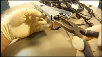
Removing the outer retainers. You may need to rock them a bit, but they'll come off without too much trouble.
Now, with the outer retainers off, you can remove the colored inner connectors using a pick tool, by pressing inward on the locks on the ends. Here's a couple of pics of where they're at:
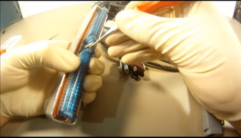
Locations of the inner pin cover lock releases (push inward on the center white sections)
With the covers removed, you'll see the pins embedded in the connector.
You're now looking for the following locations (one on each larger bank):
Blue – pin 42 (on schematics, the Blue connector is also referred to as 'C1')
Green (or Red) – pin 33 (and this one is 'C2', of course)
(if you are making a harness from scratch, you'll need Micro-Pack 100W 1.0 Terminals for the ECM end, and you should use 18-20ga wire. But if you're rolling your own, you know this, too)
The ECM actually has tiny numbers above or below each terminal on the back end of the mounting 'plug'. But for those of us with tired eyes, here's the layout of the connector:

So, from the above layout, the wire for the blue connector goes into the top row, 2nd from the left
The other wire goes into the OTHER connector, and pin '33' is on the bottom right row, 7th from the right.
You're advised to use some silicone spray to insert the pins. Don't be stingy. The connections are tight, and if you're not careful, it's *super* easy to break off a pin. Ask me how I know. Here's some more recommendations, from me, as I found this to be the most difficult part of the project:
Usually, the two ECM connection wires are pre-terminated, but temporarily fastening the main power & ground connections (ring terminals) can help hold the harness in place, while you make these connections. Being small, they can be a PITA to work with.
Take a straight pick or small awl, and give the socket a decent reaming, from both ends. If you do this right, you'll see a little bit of the rubber be pushed out of the socket (white colored, on the blue connector, and red colored, on the green / red). That's fine; just clean out the particles that are ejected. After a couple of reamings, you'll notice there's less resistance when you insert the pick. That's what you want, so ream away.
The 'inside' end has tiny plastic 'fingers' to lock the micro-pack pin into place. You can lift these up to make it easier to get the pin inserted fully (which will require insertion past the end of the metal pin; about 1/8” or so. If the wire bends, it will be nearly impossible to get it pushed into the connector. Using the flat end of one of the tools I mention below as a brace, to keep the wire straight, can help.
One source I read about on these suggested pushing the wire through, before adding the micro-pack connector pin (so that you crimp the connector on, then move it backwards to seat). I did try this, but it was difficult to terminate the micro-pack onto the wire, so I went back to the 'conventional' way.
The pins are available from Amazon; I ordered (2) packages of 12 (about $8/ea), and used about six of the (24) total. Most of the offerings are for 50-100 (or more) of these, so look for the small quantity packages.
End of Part 1...
So... I've been offline for a bit; maybe we'll subtitle this thread "What I did over my summer vacation"

(Note: This is going to be in at least two parts, as GMTN has a 10K character limit per post, and I know I'm > 15,000 already)
Covers:
99-06, 07 'Classic' GMT800 series
(photos show a P59 ECM; others similar)
During a P/S pump replacement, I decided to do the e-fan conversion since I was taking out so much stuff in the same area. These are found on the '05-up trucks, but can be retrofitted as far back as '99.
As for what you'll need...
A 34” core radiator (these are mostly found in 3/4-ton series – basically, anything with a 6.0L installed. They also should have the bungs for the oil cooler lines on the driver side (and you don't need to run lines to these; blockoff plugs are just fine, if you're not ready to install the oil cooler lines between the block mount location (just above the oil filter, sealed with its own blockoff plate, by default on the 5.3L and smaller V8s).
If you have a 1/2-ton 1500, your radiator has a 28” core, and you'll need to upgrade it in order for the new fan assembly to fit, as the assembly is too large, otherwise (and you'll need to be creative in mounting it. With the larger rad, it's a drop-in affair.
A fan harness with in-line relays to turn the fans on / off at the appropriate times. You can either order the GM part, or an aftermarket solution. Nelson Performance probably makes the best version, but they're expensive (triple the $ of what you find on Amazon). I went with the highly-rated Amazon solution.
The fan assembly. I went with an aftermarket from Rock that had a lifetime warranty. Note there are two versions – one has a 5- and 7-blade, the other has a 7- and 9-blade. Ostensibly, the 7&9 blade option is better, if you can find it.
Mine is the 5&7 combo.
A way to program your ECM fan controls. The ability is built into the P59 ECM, but turned off on the pickups before '05, because they use the mechanical fan / clutch. It's a simple matter to turn it on with HP Tuners (I'll include a screenshot or two for reference). If you don't have HPT, resources like Limeswap and ECM 4 Less are available on a mail order basis, and whomever you have locally. Yes, I can do it for you, but you'll need to purchase license credits, as my licensure with HPT is currently on a per-truck basis. PM me for more details. But I'd go with Jeremy @ Limeswap, if you want more than the fans activated. Also, return visits for your ECM with him are only $25 (as of this writing), if you want more done later.
If you have an alternator rated at less than 130A, seriously consider upgrading it to a 130A or 145A, if possible. These fans use a lot of juice (up to 40A each), and if your alternator is rated on the small side, you may find it working harder to keep up.
To start, disco the battery, and remove the upper shroud. If you need help on how to do this, stop here, save yourself a lot of trouble, and have someone do this for you. But almost everyone here knows their way around a vehicle, so...

Remove the mechanical fan / clutch. LEAVE the serpentine belt on until you get the nut loose, as it will help hold the fan stationary. If it's been a long time (or never) since the fan / clutch retaining nut has been removed, it's going to be a bit of a struggle to get it off. But it can be done (and there are plenty of tutorials available here and elsewhere). For one that's stuck on, an air hammer with the flat chisel attachment will make quick work of the job (focus on the left side of the nut, as you're facing it.) If you don't have an air compressor, you can also get it off with a cold chisel / hand sledge, or a pipe wrench. Just make sure the pulley is immobilized, and you'll get it off. If you've had the fan / clutch off beforehand, it should be a LOT easier to get the thing off, as long as you didn't torque it back on the last time you had it off (which is never needed, anyway, as centrifugal force tightens it once you start the engine.)
With the fan / clutch removed, you'll have enough room to remove the lower shroud. Notice that I didn't mention draining coolant / disconnecting radiator hoses? That's because you don't have to. It'll take a bit of fiddling, but you can get it out (in my case, I was able to go from underneath, and twist / turn it so that it came up through the passenger side opening. In my case, I think I still had the fan on, even – but if you can remove it, it'll make it that much easier, of course. For that reason, you can probably leave the serpentine belt attached, as well, if your project is starting / ending with this mod.
With the upper fan shroud and the mechanical fan / clutch removed, you should have plenty of room to remove the ECM from its housing, and disconnect the two harness connectors (you'll need a 7mm socket for the center retaining bolt). If you haven't disconnected the battery yet, do so, before touching the ECM. The last thing you want to do is to short out & have to replace the ECM.
Now, with the two harness connectors removed, you'll need to remove the retainers on both sides, in order to reach the pinouts. For the outer (large gray) retainers, take a pair of pliers, and squeeze the tabs on the ends inward, then lift them up and off. There are also locking tabs along both of the long sides; press inward to release them. These aren't as flexible as the end connectors, so use a bit more care, if you don't want to crack off the tabs.

Removing the outer retainers. You may need to rock them a bit, but they'll come off without too much trouble.
Now, with the outer retainers off, you can remove the colored inner connectors using a pick tool, by pressing inward on the locks on the ends. Here's a couple of pics of where they're at:

Locations of the inner pin cover lock releases (push inward on the center white sections)
With the covers removed, you'll see the pins embedded in the connector.
You're now looking for the following locations (one on each larger bank):
Blue – pin 42 (on schematics, the Blue connector is also referred to as 'C1')
Green (or Red) – pin 33 (and this one is 'C2', of course)
(if you are making a harness from scratch, you'll need Micro-Pack 100W 1.0 Terminals for the ECM end, and you should use 18-20ga wire. But if you're rolling your own, you know this, too)
The ECM actually has tiny numbers above or below each terminal on the back end of the mounting 'plug'. But for those of us with tired eyes, here's the layout of the connector:

So, from the above layout, the wire for the blue connector goes into the top row, 2nd from the left
The other wire goes into the OTHER connector, and pin '33' is on the bottom right row, 7th from the right.
You're advised to use some silicone spray to insert the pins. Don't be stingy. The connections are tight, and if you're not careful, it's *super* easy to break off a pin. Ask me how I know. Here's some more recommendations, from me, as I found this to be the most difficult part of the project:
Usually, the two ECM connection wires are pre-terminated, but temporarily fastening the main power & ground connections (ring terminals) can help hold the harness in place, while you make these connections. Being small, they can be a PITA to work with.
Take a straight pick or small awl, and give the socket a decent reaming, from both ends. If you do this right, you'll see a little bit of the rubber be pushed out of the socket (white colored, on the blue connector, and red colored, on the green / red). That's fine; just clean out the particles that are ejected. After a couple of reamings, you'll notice there's less resistance when you insert the pick. That's what you want, so ream away.
The 'inside' end has tiny plastic 'fingers' to lock the micro-pack pin into place. You can lift these up to make it easier to get the pin inserted fully (which will require insertion past the end of the metal pin; about 1/8” or so. If the wire bends, it will be nearly impossible to get it pushed into the connector. Using the flat end of one of the tools I mention below as a brace, to keep the wire straight, can help.
One source I read about on these suggested pushing the wire through, before adding the micro-pack connector pin (so that you crimp the connector on, then move it backwards to seat). I did try this, but it was difficult to terminate the micro-pack onto the wire, so I went back to the 'conventional' way.
The pins are available from Amazon; I ordered (2) packages of 12 (about $8/ea), and used about six of the (24) total. Most of the offerings are for 50-100 (or more) of these, so look for the small quantity packages.
End of Part 1...
Last edited:

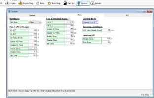
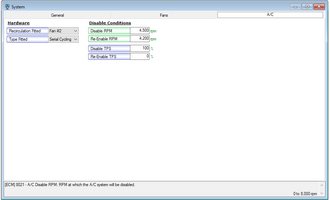

 , as well as what this little adventure cost (time and $).
