For anyone following along and having Similar Diagnostic Questions...
(1) Before attempting any Tests... Start by First Measuring your Battery (B+) Voltage and establish a Base Line. Remember... Battery Voltage is NOT System Voltage. Ordinary, Nominal Voltage is above 12.5 Volts DC.
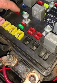
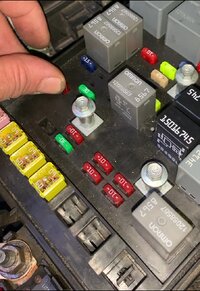
(2) VVTs, EFIs, Fuse Box Relays, SAIS and Starter Solenoids are ALL just THAT... SOLENOIDS. There is
NOTHING Subtle about How Solenoids WORK.
(3) As Electro-Magnetic Devices... Their Speed and Reaction performances are occurring at "The Speed of Light"
(Well... With Collapsing Magnetic Fields... Almost) and are responsive to the Size of their Movable Iron or Steel Cores... Plus...The Amount of Current moving through their Circuits... Plus.... the Number of Windings of Wire present in their encircling Copper Coils.... Plus... Being modified by the Length or Distance they must Travel before they Mechanically either Close Relay Contacts or Close - Open a Valve Segments inside of any Device... say like an EGR (Exhausr Gas Re-Circulation) Valve that may have as many as THREE Separate Solenoids.
(4) Consequently, the Level of Sound created by their activation will vary depending upon what their intended functions are...Plus... How Rapidly and How Often they must perform their Activities.
(5) So... Relying upon any "Decibel Level" emanating out or any of these Solenoid Devices would be an unreliable way to figure out whether or not they are performing properly.
(6) However... If you can HEAR the Activation as it happens when directed by say... A Bi-Directional Instruction sent either from and to either the PCM during its timely Commands....or...coming from a Deliberate Test initiated from a GOOD Bi-Directional Scan Tool... If you can HEAR any activation...THAT should indicate that the Solenoid is Working.
(7) The Last Issue for Modern Electronically Controlled Vehicles ...is PMW...or Pulse Width Modulation frequently used to
rapidly turn Solenoids On and Off depending upon the demands required by the PCM and the prevailing operational conditions going on.
(8) The entire reason for having these Fluid and Vapor Valves under the watchful gaze of the PCM is to prevent as much as possible, the escape of Fuel, Oil and Incomplete Combustion VOCs (Volatile Organic Compounds) from escaping and getting out into the Atmosphere. The idea is to either Capture and Store them temporarily inside of a Canister filled with pellets of Carbon... or simply re-route them directly back through the Air Stream and into the Engine to be burned as part of the normal Four Stroke Combustion Cycle.
(9)
THINK ABOUT THE PHYSICAL SYSTEM AND ITS COMPONENTS IN YOUR MIND... and then logically examine ALL of them in the Order they Come On Line... and your Diagnosis will be Thorough, Complete... AND much more likely to put you in the
EXACT Place where the Failure is occurring ...
Like an Internally Stretched or Broken Wire that Touches when the SUV is COLD... but separates and Breaks the Circuit when the SUV is HOT...Or...Vice Versa!
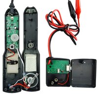
(10) Try using a Simple, Inexpensive
Short, Open or Broken Circuit Continuity Tracing Kit that will let you connect a Transceiver at the Circuit Suspevt Wire Point of Origin... and then LISTEN to the Second Portion of the Device as it Senses the Invisible... and allows you to Locate
precisely where the Continuity of the activated Wire STOPS.
Like THIS Kit that You can also use to Duplicate THIS Demonstration on Your TRAILBLAZER - ENVOY:
Available on Amazon via THIS GMT Nation Link:
View attachment 108538View attachment 108539View attachment 108540View attachment 108541View attachment 108542View attachment 108543View attachment 108544View attachment 108545